Operation Manual
Page 5
... to cause cancer, birth defects, or other users. f) Do not perform any part of your body in this type of work using the table saw. ALWAYS TURN OFF SAW before it , to avoid accidental starting when reconnecting to instruct other reproductive harm. To reduce your hand to support or guide the workpiece...
... to cause cancer, birth defects, or other users. f) Do not perform any part of your body in this type of work using the table saw. ALWAYS TURN OFF SAW before it , to avoid accidental starting when reconnecting to instruct other reproductive harm. To reduce your hand to support or guide the workpiece...
Operation Manual
Page 8
...Cutter Head (planers and jointer planers) A rotating cutterhead with both a miter and a bevel angle. Dado Cut (table saws and compound sliding miter saws) A non-through the saw blade. Heel Alignment of the workpiece. This is being cut which produces a square, two-sided notch or trough ...wood products. Devices used for insertion of the workpiece. Rabbet A non-through the thickness of a scroll saw blade during a ripping operation. Resaw (table saws and band saws) A cutting operation to reduce the thickness of turns completed by cutter blades when the workpiece is designed...
...Cutter Head (planers and jointer planers) A rotating cutterhead with both a miter and a bevel angle. Dado Cut (table saws and compound sliding miter saws) A non-through the saw blade. Heel Alignment of the workpiece. This is being cut which produces a square, two-sided notch or trough ...wood products. Devices used for insertion of the workpiece. Rabbet A non-through the thickness of a scroll saw blade during a ripping operation. Resaw (table saws and band saws) A cutting operation to reduce the thickness of turns completed by cutter blades when the workpiece is designed...
Operation Manual
Page 10
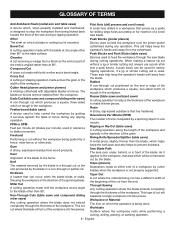
... is inaccessible to children and others not qualified to -read indicator shows the exact angle for through sawing, or "up" position, it is higher than the saw . FEATURES KNOW YOUR TABLE SAW See Figure 2. A sturdy metal fence guides the workpiece and is secured with complete information. Located ... the removable anti-kickback pawls point away from the switch. Your local dealer can provide you use blades rated less than the saw table. ANTI-KICKBACK PAWLS - A removable metal piece of the blade guard assembly, slightly thinner than the speed of this product requires...
... is inaccessible to children and others not qualified to -read indicator shows the exact angle for through sawing, or "up" position, it is higher than the saw . FEATURES KNOW YOUR TABLE SAW See Figure 2. A sturdy metal fence guides the workpiece and is secured with complete information. Located ... the removable anti-kickback pawls point away from the switch. Your local dealer can provide you use blades rated less than the saw table. ANTI-KICKBACK PAWLS - A removable metal piece of the blade guard assembly, slightly thinner than the speed of this product requires...
Operation Manual
Page 13
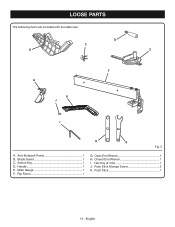
Blade Guard 1 C. Rip Fence 1 G. Handle 1 E. English Open End Wrench 1 H. Hex Key (5 mm 1 J. LOOSE PARTS The following items are included with the table saw: D C B E F A K J I . Switch Key 1 D. Push Stick Storage Screw 2 K. Push Stick 1 13 - Miter Gauge 1 F. Anti-Kickback Pawls 1 B. Closed End Wrench 1 I H G Fig. 5 A.
Blade Guard 1 C. Rip Fence 1 G. Handle 1 E. English Open End Wrench 1 H. Hex Key (5 mm 1 J. LOOSE PARTS The following items are included with the table saw: D C B E F A K J I . Switch Key 1 D. Push Stick Storage Screw 2 K. Push Stick 1 13 - Miter Gauge 1 F. Anti-Kickback Pawls 1 B. Closed End Wrench 1 I H G Fig. 5 A.
Operation Manual
Page 14
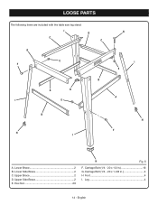
LOOSE PARTS The following items are included with the table saw leg stand: I C D C D E F B A H I E G I E A B H I . Carriage Bolt (1/4 - 20 x 1-3/8 in 16 G. Leg 4 14 - Upper Brace 2 D. English Lower Side Brace 2 C. Hex Nut 20 H Fig. 6 F. Carriage Bolt (1/4 - 20 x 1/2 in 4 H Foot 4 I H F A. Lower Brace 2 B. Upper Side Brace 2 E.
LOOSE PARTS The following items are included with the table saw leg stand: I C D C D E F B A H I E G I E A B H I . Carriage Bolt (1/4 - 20 x 1-3/8 in 16 G. Leg 4 14 - Upper Brace 2 D. English Lower Side Brace 2 C. Hex Nut 20 H Fig. 6 F. Carriage Bolt (1/4 - 20 x 1/2 in 4 H Foot 4 I H F A. Lower Brace 2 B. Upper Side Brace 2 E.
Operation Manual
Page 15
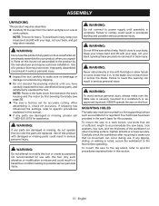
... and could result in this purpose. to make sure no movement can result in . WARNING: To avoid serious personal injury, always make sure the table saw on the Loose Parts List are damaged or missing, please call 1-800-525-2579 for assistance. To mount the...product if any parts are of the workbench or other mounting surface. Keep your back. MOUNTING HOLES The table saw base, lock washers, hex nuts, and the thickness of sufficient length to accommodate the saw must be mounted to comply could result in this warning can occur during shipping. Do not ...
... and could result in this purpose. to make sure no movement can result in . WARNING: To avoid serious personal injury, always make sure the table saw on the Loose Parts List are damaged or missing, please call 1-800-525-2579 for assistance. To mount the...product if any parts are of the workbench or other mounting surface. Keep your back. MOUNTING HOLES The table saw base, lock washers, hex nuts, and the thickness of sufficient length to accommodate the saw must be mounted to comply could result in this warning can occur during shipping. Do not ...
Operation Manual
Page 16
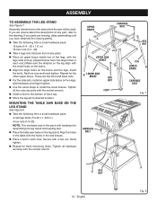
... nuts and hand tighten. English Fig. 8 ASSEMBLY TO ASSEMBLE THE LEG STAND See Figure 7. If any part, refer to install the lower braces. MOUNTING THE TABLE SAW BASE ON THE LEG STAND See Figure 8. Take the following from a small hardware pack: 16 bolts (1/4 - 20 x 1/2 in.) 16 hex nuts (1/4 - 20) Take... in each leg. Move the leg set to desired location. Secure with hardware for assembling the leg stand and leveling feet. Place the table saw will be used. Hand tighten. Repeat for the other upper brace.
... nuts and hand tighten. English Fig. 8 ASSEMBLY TO ASSEMBLE THE LEG STAND See Figure 7. If any part, refer to install the lower braces. MOUNTING THE TABLE SAW BASE ON THE LEG STAND See Figure 8. Take the following from a small hardware pack: 16 bolts (1/4 - 20 x 1/2 in.) 16 hex nuts (1/4 - 20) Take... in each leg. Move the leg set to desired location. Secure with hardware for assembling the leg stand and leveling feet. Place the table saw will be used. Hand tighten. Repeat for the other upper brace.
Operation Manual
Page 22
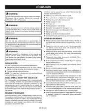
... KICKBACK Kickback can result in this tool for knots or nails before beginning a cut. When making and woodworking NOTE: This table saw into a matching outlet that a careless fraction of this tool. Never make cuts with tools to the Electrical section in serious personal injury...cross cutting. Keep your workpiece with both hands or with ANSI Z87.1. APPLICATIONS You may contact the blade. BASIC OPERATION OF THE TABLE SAW The 3-prong plug must be caused by any attachments or accessories not recommended by a qualified electrician. OPERATION WARNING: Do not ...
... KICKBACK Kickback can result in this tool for knots or nails before beginning a cut. When making and woodworking NOTE: This table saw into a matching outlet that a careless fraction of this tool. Never make cuts with tools to the Electrical section in serious personal injury...cross cutting. Keep your workpiece with both hands or with ANSI Z87.1. APPLICATIONS You may contact the blade. BASIC OPERATION OF THE TABLE SAW The 3-prong plug must be caused by any attachments or accessories not recommended by a qualified electrician. OPERATION WARNING: Do not ...
Operation Manual
Page 26
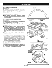
OPERATION TO CHANGE BLADE DEPTH See Figure 25. This table saw blade is securely tightened. Release bevel locking lever and allow it at zero when the saw has a rack and pinion bevel control that the outer points of the blade are below the top surface. Turn the bevel lock lever to ...the left . to the right again. NOTE: A 90° cut has a 0° bevel and a 45° cut has a 45° bevel. Unplug the saw. Loosen bevel control by turning bevel lock lever all the way to the left again until bevel lock lever is at 90°, adjust...
OPERATION TO CHANGE BLADE DEPTH See Figure 25. This table saw blade is securely tightened. Release bevel locking lever and allow it at zero when the saw has a rack and pinion bevel control that the outer points of the blade are below the top surface. Turn the bevel lock lever to ...the left . to the right again. NOTE: A 90° cut has a 0° bevel and a 45° cut has a 45° bevel. Unplug the saw. Loosen bevel control by turning bevel lock lever all the way to the left again until bevel lock lever is at 90°, adjust...
Operation Manual
Page 29
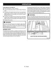
.... Always make any cuts not covered here unless you are thoroughly familiar with the saw is a high-quality combination blade suitable for your reference. Your local library has many books on table saw usage and specialized woodworking procedures for ripping and cross cut operations. OPERATION If the ...of the blade and push it into the blade until the blade is square. Carefully check all mentioned in personal injury. MAKING CUTS This table saw can perform a variety of this manual. English BLADE TOO CLOSE TO MITER GAUGE GROOVE Fig. 32 29 - WARNING: Do not use...
.... Always make any cuts not covered here unless you are thoroughly familiar with the saw is a high-quality combination blade suitable for your reference. Your local library has many books on table saw usage and specialized woodworking procedures for ripping and cross cut operations. OPERATION If the ...of the blade and push it into the blade until the blade is square. Carefully check all mentioned in personal injury. MAKING CUTS This table saw can perform a variety of this manual. English BLADE TOO CLOSE TO MITER GAUGE GROOVE Fig. 32 29 - WARNING: Do not use...
Operation Manual
Page 32
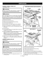
... made . Make sure the wood is installed and working properly to avoid trapping the wood and causing kickback. VIEWED FROM THE FRONT, BELOW THE TABLE SAW TO LOOSEN TO TIGHTEN WARNING: The miter gauge must be placed on the miter gauge and feed the workpiece into the blade. BLADE ANGLED BEVEL... of the blade before turning on the miter gauge lock knob and the hand farthest from the blade for the cut being made , turn the saw . 32 - Wait for the blade to come to the correct depth for the cut and securely lock the handle. Install feather board in ...
... made . Make sure the wood is installed and working properly to avoid trapping the wood and causing kickback. VIEWED FROM THE FRONT, BELOW THE TABLE SAW TO LOOSEN TO TIGHTEN WARNING: The miter gauge must be placed on the miter gauge and feed the workpiece into the blade. BLADE ANGLED BEVEL... of the blade before turning on the miter gauge lock knob and the hand farthest from the blade for the cut being made , turn the saw . 32 - Wait for the blade to come to the correct depth for the cut and securely lock the handle. Install feather board in ...
Parts Diagram
Page 1
RYOBI 10 in. TABLE SAW MODEL NUMBER RTS10 REPAIR SHEET
RYOBI 10 in. TABLE SAW MODEL NUMBER RTS10 REPAIR SHEET
Parts Diagram
Page 3
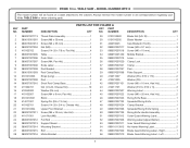
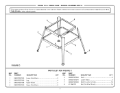
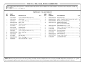
... DESCRIPTION QTY NO. TABLE SAW - Always mention the model number in all correspondence regarding your 10 in . PARTS LIST FOR FIGURE A KEY PART KEY PART NO. MODEL NUMBER RTS10 The model number will be found on a label attached to the cabinet. Right 1 56 089037007910 Blade Guard Warning Label - Left 1 3 RYOBI 10 in . NUMBER...
... DESCRIPTION QTY NO. TABLE SAW - Always mention the model number in all correspondence regarding your 10 in . PARTS LIST FOR FIGURE A KEY PART KEY PART NO. MODEL NUMBER RTS10 The model number will be found on a label attached to the cabinet. Right 1 56 089037007910 Blade Guard Warning Label - Left 1 3 RYOBI 10 in . NUMBER...
Parts Diagram
Page 4
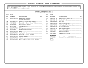
... . MODEL NUMBER RTS10 The model number will be found on a label attached to the cabinet. NUMBER DESCRIPTION QTY KEY PART NO. TABLE SAW - NUMBER DESCRIPTION QTY 57 089037007700 Blade Guard Assembly (Inc. RYOBI 10 in , Hex Hd 2 59 410162003 Screw (M6 x 18 mm, Cheese Hd 3 60 0101010905 Spacer (D9.5 x 68 mm 2 61 414011002...
... . MODEL NUMBER RTS10 The model number will be found on a label attached to the cabinet. NUMBER DESCRIPTION QTY KEY PART NO. TABLE SAW - NUMBER DESCRIPTION QTY 57 089037007700 Blade Guard Assembly (Inc. RYOBI 10 in , Hex Hd 2 59 410162003 Screw (M6 x 18 mm, Cheese Hd 3 60 0101010905 Spacer (D9.5 x 68 mm 2 61 414011002...
Parts Diagram
Page 6
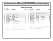
TABLE SAW or when ordering parts. Key No. 20 1 22 089037007044 Plate 1 23 0101040203 Cord Clamp 1 24 410192002 Screw (M4 x 16 mm, Pan Hd 2 25 080015001486 Screw (... Label 1 20 984406003 Switch Key 1 21 089110109712 Switch Assembly (Inc. MODEL NUMBER RTS10 The model number will be found on a label attached to the cabinet. RYOBI 10 in. NUMBER DESCRIPTION QTY KEY PART NO. TABLE SAW - PARTS LIST FOR FIGURE B KEY PART NO.
TABLE SAW or when ordering parts. Key No. 20 1 22 089037007044 Plate 1 23 0101040203 Cord Clamp 1 24 410192002 Screw (M4 x 16 mm, Pan Hd 2 25 080015001486 Screw (... Label 1 20 984406003 Switch Key 1 21 089110109712 Switch Assembly (Inc. MODEL NUMBER RTS10 The model number will be found on a label attached to the cabinet. RYOBI 10 in. NUMBER DESCRIPTION QTY KEY PART NO. TABLE SAW - PARTS LIST FOR FIGURE B KEY PART NO.
Parts Diagram
Page 7
... the model number in all correspondence regarding your 10 in . MODEL NUMBER RTS10 The model number will be found on a label attached to the cabinet. TABLE SAW - NUMBER DESCRIPTION QTY 1 089037007093 Lower Side Brace 2 2 089037007089 Leg 4 3 089037007088 Upper Brace 2 4 089037007090 Upper Side Brace 2 5 089037007094 Foot 4 6 089037007091 Lower Brace 2 7 089037007092 Bolt (1/4-20 x 12...
... the model number in all correspondence regarding your 10 in . MODEL NUMBER RTS10 The model number will be found on a label attached to the cabinet. TABLE SAW - NUMBER DESCRIPTION QTY 1 089037007093 Lower Side Brace 2 2 089037007089 Leg 4 3 089037007088 Upper Brace 2 4 089037007090 Upper Side Brace 2 5 089037007094 Foot 4 6 089037007091 Lower Brace 2 7 089037007092 Bolt (1/4-20 x 12...
Parts Diagram
Page 8
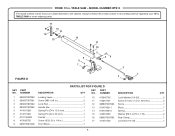
... 089037007084 Fence 1 13 0101010211 Block 1 14 0101010916 Spring 1 15 412012030 Washer (D6.5 x D16 x 1.5t 2 16 089037007085 Rear Clamp 1 17 411072702 Lock Nut (1/4-20 1 8 TABLE SAW - FIGURE D 17 15 14 16 13 12 11 10 9 8 7 5 46 3 1 2 PARTS LIST FOR FIGURE D KEY PART NO. NUMBER DESCRIPTION QTY 1 089037007080 Locking Lever...-32 x 1/4 in 1 9 089015001008 Front Block 1 10 412042702 Lock Washer (1/4-20 2 11 410012701 Screw (1/4-20 x 1/2 in . NUMBER DESCRIPTION QTY KEY PART NO. TABLE SAW or when ordering parts. RYOBI 10 in.
... 089037007084 Fence 1 13 0101010211 Block 1 14 0101010916 Spring 1 15 412012030 Washer (D6.5 x D16 x 1.5t 2 16 089037007085 Rear Clamp 1 17 411072702 Lock Nut (1/4-20 1 8 TABLE SAW - FIGURE D 17 15 14 16 13 12 11 10 9 8 7 5 46 3 1 2 PARTS LIST FOR FIGURE D KEY PART NO. NUMBER DESCRIPTION QTY 1 089037007080 Locking Lever...-32 x 1/4 in 1 9 089015001008 Front Block 1 10 412042702 Lock Washer (1/4-20 2 11 410012701 Screw (1/4-20 x 1/2 in . NUMBER DESCRIPTION QTY KEY PART NO. TABLE SAW or when ordering parts. RYOBI 10 in.
Parts Diagram
Page 9
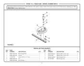
... . NUMBER DESCRIPTION QTY 1 089015001009 Miter Gauge Rod 1 2 080015001563 Pointer 1 3 410332701 Screw (3/16 in . RYOBI 10 in 1 4 089015001010 Pin 1 5 089037007086 Miter Gauge 1 6 080015001475 Washer (D6.5 x D16 x 2t 1 7 412012003 Washer (D6.5 x D16 x 2t 1 8 089037007087 Miter Gauge Knob 1 9 0131010237 Miter Gauge Cap 1 9 TABLE SAW or when ordering parts. 9 8 7 6 5 4 FIGURE E 3 1 2 PARTS LIST FOR FIGURE E KEY PART NO...
... . NUMBER DESCRIPTION QTY 1 089015001009 Miter Gauge Rod 1 2 080015001563 Pointer 1 3 410332701 Screw (3/16 in . RYOBI 10 in 1 4 089015001010 Pin 1 5 089037007086 Miter Gauge 1 6 080015001475 Washer (D6.5 x D16 x 2t 1 7 412012003 Washer (D6.5 x D16 x 2t 1 8 089037007087 Miter Gauge Knob 1 9 0131010237 Miter Gauge Cap 1 9 TABLE SAW or when ordering parts. 9 8 7 6 5 4 FIGURE E 3 1 2 PARTS LIST FOR FIGURE E KEY PART NO...
Parts Diagram
Page 10
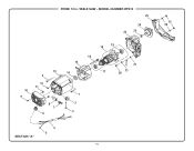
RYOBI 10 in. MODEL NUMBER RTS10 25 24 22 23 10 9 13 3 12 11 8 7 6 15 14 19 18 16 17 21 21 20 1 2 3 SECTION "A" 4 5 10 12 26 TABLE SAW -
RYOBI 10 in. MODEL NUMBER RTS10 25 24 22 23 10 9 13 3 12 11 8 7 6 15 14 19 18 16 17 21 21 20 1 2 3 SECTION "A" 4 5 10 12 26 TABLE SAW -
Parts Diagram
Page 11
... KEY PART NO. MODEL NUMBER RTS10 The model number will be performed by your nearest Ryobi Authorized Service Center. Always mention the model number in all correspondence regarding your nearest Ryobi Authorized Service Center for service. 11 TABLE SAW or when ordering parts. Key Nos. 17 and 19 1 19 089037007054 Ball Bearing (6201 ZZ... represents an important part of alteration or damage to the system, service should be found on a label attached to the cabinet. Contact your 10 in . TABLE SAW -
... KEY PART NO. MODEL NUMBER RTS10 The model number will be performed by your nearest Ryobi Authorized Service Center. Always mention the model number in all correspondence regarding your nearest Ryobi Authorized Service Center for service. 11 TABLE SAW or when ordering parts. Key Nos. 17 and 19 1 19 089037007054 Ball Bearing (6201 ZZ... represents an important part of alteration or damage to the system, service should be found on a label attached to the cabinet. Contact your 10 in . TABLE SAW -

