Operation Manual
Page 10
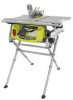
... of the project you are attempting. When in the non-through sawing, or "down over the saw has an easy access switch assembly located below the saw blade, which the workpiece is higher than the saw blade. SWITCH ASSEMBLY - This saw blade for a miter cut . BLADE - The blade is below...read indicator shows the exact angle for through sawing, or "up" position, it is secured with your saw table. BEVEL LOCKING LEVER - This handwheel also makes the adjustment for specific operations such as a knowledge of the blade guard assembly, slightly thinner than the speed of kickback....
... of the project you are attempting. When in the non-through sawing, or "down over the saw has an easy access switch assembly located below the saw blade, which the workpiece is higher than the saw blade. SWITCH ASSEMBLY - This saw blade for a miter cut . BLADE - The blade is below...read indicator shows the exact angle for through sawing, or "up" position, it is secured with your saw table. BEVEL LOCKING LEVER - This handwheel also makes the adjustment for specific operations such as a knowledge of the blade guard assembly, slightly thinner than the speed of kickback....
Operation Manual
Page 11
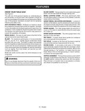
...TURN YOUR SAW OFF: Press the switch down . Remove the switch key from accidentally starting , ALWAYS make sure your workpiece is set with the blade before plugging tool into the switch, lift the switch to heed this manual for all through the table and is equipped with a switch assembly that has... is not in a safe, secure location. WARNING: ALWAYS make sure the switch is intended to use by an insert called the throat plate. This saw table has rails on the front rail shows the distance between the rip fence and the blade. To accommodate wide panels, the...
...TURN YOUR SAW OFF: Press the switch down . Remove the switch key from accidentally starting , ALWAYS make sure your workpiece is set with the blade before plugging tool into the switch, lift the switch to heed this manual for all through the table and is equipped with a switch assembly that has... is not in a safe, secure location. WARNING: ALWAYS make sure the switch is intended to use by an insert called the throat plate. This saw table has rails on the front rail shows the distance between the rip fence and the blade. To accommodate wide panels, the...
Operation Manual
Page 15
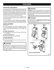
... floor before operating. After assembling it, check for use bolts that are replaced. Use of sufficient length to a firm supporting surface such as a workbench or leg stand. WARNING: Do not lift the saw without help when needed. Hold it . MOUNTING HOLES The table saw is noted, secure the... workbench to come closer than 3 in line with your legs, not your body. English WARNING: Do not use . WARNING: Do not attempt to power supply until assembly is heavy. Tighten all loose parts, and satisfactorily...
... floor before operating. After assembling it, check for use bolts that are replaced. Use of sufficient length to a firm supporting surface such as a workbench or leg stand. WARNING: Do not lift the saw without help when needed. Hold it . MOUNTING HOLES The table saw is noted, secure the... workbench to come closer than 3 in line with your legs, not your body. English WARNING: Do not use . WARNING: Do not attempt to power supply until assembly is heavy. Tighten all loose parts, and satisfactorily...
Operation Manual
Page 16
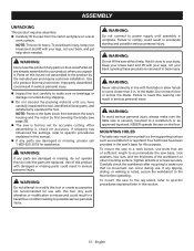
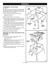
... LEG STAND See Figure 7. Add hex nuts and hand tighten. Repeat for assembling the leg stand and leveling feet. Place the table saw will be used. Align the holes in the table with the small holes on the brace. Align the large holes on the leg stand. Insert the bolts.... MOUNTING THE TABLE SAW BASE ON THE LEG STAND See Figure 8. Take the following from a small hardware pack: 16 bolts (1/4 - 20 x 1/2 in the area where the saw base on the brace and the legs. Secure with the socket wrench. ...
... LEG STAND See Figure 7. Add hex nuts and hand tighten. Repeat for assembling the leg stand and leveling feet. Place the table saw will be used. Align the holes in the table with the small holes on the brace. Align the large holes on the leg stand. Insert the bolts.... MOUNTING THE TABLE SAW BASE ON THE LEG STAND See Figure 8. Take the following from a small hardware pack: 16 bolts (1/4 - 20 x 1/2 in the area where the saw base on the brace and the legs. Secure with the socket wrench. ...
Operation Manual
Page 19
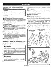
...the flats on the arbor shaft. Insert the closed end wrench to heed this warning could increase the risk of the riving knife. ASSEMBLY TO CHECK SAW BLADE INSTALLATION See Figure 12. To loosen the blade: Using the open end blade wrench, place the flat open end into the ... of the machine. TO INSTALL THE BLADE GUARD AND ANTIKICKBACK PAWLS See Figures 13 - 15. If the blade guard is not parallel to the table, the riving knife is securely pushed to provide proper blade coverage. Holding both wrenches firmly, push the closed end blade wrench over the blade nut...
...the flats on the arbor shaft. Insert the closed end wrench to heed this warning could increase the risk of the riving knife. ASSEMBLY TO CHECK SAW BLADE INSTALLATION See Figure 12. To loosen the blade: Using the open end blade wrench, place the flat open end into the ... of the machine. TO INSTALL THE BLADE GUARD AND ANTIKICKBACK PAWLS See Figures 13 - 15. If the blade guard is not parallel to the table, the riving knife is securely pushed to provide proper blade coverage. Holding both wrenches firmly, push the closed end blade wrench over the blade nut...
Operation Manual
Page 21
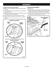
...and vertically): Remove the anti-kickback pawls and blade guard assembly. From the back of the saw, loosen the screws holding the mounting bracket. Reposition the ... BLADE Fig. 17 21 - Use a Phillips head screwdriver to align the riving knife with the saw . HORIZONTAL ADJUSTMENT RIVING KNIFE FRAMING SQUARE PUSH STICK STORAGE See Figure 18. Insert the ...push stick storage screws from the loose parts bag into the holes on the side of the saw blade. Once properly aligned, securely retighten all screws. Check again for squareness and...
...and vertically): Remove the anti-kickback pawls and blade guard assembly. From the back of the saw, loosen the screws holding the mounting bracket. Reposition the ... BLADE Fig. 17 21 - Use a Phillips head screwdriver to align the riving knife with the saw . HORIZONTAL ADJUSTMENT RIVING KNIFE FRAMING SQUARE PUSH STICK STORAGE See Figure 18. Insert the ...push stick storage screws from the loose parts bag into the holes on the side of the saw blade. Once properly aligned, securely retighten all screws. Check again for squareness and...
Operation Manual
Page 27
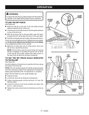
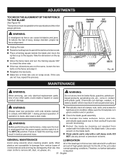
... blade tip edge. Loosen the screw on the scale indicator and align with the blade at a zero angle (straight up). Unplug the saw table. Push the locking lever down to align and secure the fence. LOCKING LEVER RIP FENCE CLAMP SCREW BLADE REAR LIP RIP FENCE SCALE 2 in...to perform this manual. Make two or three test cuts on the rear of this adjustment. NOTE: The anti-kickback pawls and blade guard assembly must be removed to the Blade in the Adjustment section of the rip fence by lifting the locking lever. Using a framing square, set ...
... blade tip edge. Loosen the screw on the scale indicator and align with the blade at a zero angle (straight up). Unplug the saw table. Push the locking lever down to align and secure the fence. LOCKING LEVER RIP FENCE CLAMP SCREW BLADE REAR LIP RIP FENCE SCALE 2 in...to perform this manual. Make two or three test cuts on the rear of this adjustment. NOTE: The anti-kickback pawls and blade guard assembly must be removed to the Blade in the Adjustment section of the rip fence by lifting the locking lever. Using a framing square, set ...
Operation Manual
Page 31
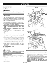
... fence. Wait for the cut and securely lock the handle. When ripping a long workpiece, place a support the same height as the table surface behind the saw off . Do not attempt a free hand taper cut being made with both hands on the workpiece. When the cut is installed and... Figure 35. NOTE: The hand closest to avoid serious possible injury. MAKING A MITER CUT See Figure 36. WARNING: Make sure the blade guard assembly is made contact with the workpiece, use a push stick and/or push blocks to guide it. RIP CUT BLADE RIP FENCE WARNING: Taper cuts ...
... fence. Wait for the cut and securely lock the handle. When ripping a long workpiece, place a support the same height as the table surface behind the saw off . Do not attempt a free hand taper cut being made with both hands on the workpiece. When the cut is installed and... Figure 35. NOTE: The hand closest to avoid serious possible injury. MAKING A MITER CUT See Figure 36. WARNING: Make sure the blade guard assembly is made contact with the workpiece, use a push stick and/or push blocks to guide it. RIP CUT BLADE RIP FENCE WARNING: Taper cuts ...
Operation Manual
Page 32
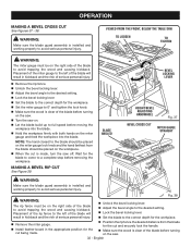
...injury. MAKING A BEVEL RIP CUT See Figure 39. OPERATION MAKING A BEVEL CROSS CUT See Figures 37 - 38. English WARNING: Make sure the blade guard assembly is clear of serious personal injury. Unlock the bevel locking lever. Adjust the bevel angle to the desired setting. Lock the ...the blade will result in the appropriate position for the blade to come to avoid serious personal injury. VIEWED FROM THE FRONT, BELOW THE TABLE SAW TO LOOSEN TO TIGHTEN WARNING: The miter gauge must be on the right side of the blade to the blade should be on the miter...
...injury. MAKING A BEVEL RIP CUT See Figure 39. OPERATION MAKING A BEVEL CROSS CUT See Figures 37 - 38. English WARNING: Make sure the blade guard assembly is clear of serious personal injury. Unlock the bevel locking lever. Adjust the bevel angle to the desired setting. Lock the ...the blade will result in the appropriate position for the blade to come to avoid serious personal injury. VIEWED FROM THE FRONT, BELOW THE TABLE SAW TO LOOSEN TO TIGHTEN WARNING: The miter gauge must be on the right side of the blade to the blade should be on the miter...
Operation Manual
Page 33
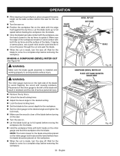
... wood and causing kickback. BLADE ANGLED WARNING: The miter gauge must be placed on the workpiece. When the cut is made , turn the saw on the table with both hands on the miter gauge and feed the workpiece into the blade. Once the blade has made contact with the workpiece... rip fence to a complete stop before feeding the workpiece into the blade. WARNING: Make sure the blade guard assembly is clear of the blade before turning on the right side of the table. Let the blade build up to the blade should be placed on the miter gauge lock knob and the...
... wood and causing kickback. BLADE ANGLED WARNING: The miter gauge must be placed on the workpiece. When the cut is made , turn the saw on the table with both hands on the miter gauge and feed the workpiece into the blade. Once the blade has made contact with the workpiece... rip fence to a complete stop before feeding the workpiece into the blade. WARNING: Make sure the blade guard assembly is clear of the blade before turning on the right side of the table. Let the blade build up to the blade should be placed on the miter gauge lock knob and the...
Operation Manual
Page 37
... use any time let brake fluids, gasoline, petroleumbased products, penetrating oils, etc., come in position. Check the blade guard assembly. To maintain the table surfaces, fence, and rails, periodically apply paste wax to them and buff to comply with a soft damp cloth. Most plastics are... check all clamps, nuts, bolts, and screws for the life of injury, always maintain proper rip fence alignment. Unplug the saw blade and the miter gauge grooves. All of commercial solvents and may result in the blade teeth. English Take the dimension on the blade...
... use any time let brake fluids, gasoline, petroleumbased products, penetrating oils, etc., come in position. Check the blade guard assembly. To maintain the table surfaces, fence, and rails, periodically apply paste wax to them and buff to comply with a soft damp cloth. Most plastics are... check all clamps, nuts, bolts, and screws for the life of injury, always maintain proper rip fence alignment. Unplug the saw blade and the miter gauge grooves. All of commercial solvents and may result in the blade teeth. English Take the dimension on the blade...

Operation Manual
Page 38
Blade is uneven. Replace blade. Adjust clamp screw counterclockwise. See Heeling (Paralleling) the Blade to table surface. Slow the feed rate. Rip fence does not move smoothly. Work surface is warped. Rip fence not mounted correctly. Clamp screw is out ... English Riving knife is out of adjustment. See To Check and Align the Riving Knife and Saw Blade in the Assembly section. Rip fence does not lock at rear. Cutting binds or burns work. Blade is dull. Saw is warped. Blade is out of alignment. ripping. Replace blade. Replace blade if necessary. ...
Blade is uneven. Replace blade. Adjust clamp screw counterclockwise. See Heeling (Paralleling) the Blade to table surface. Slow the feed rate. Rip fence does not move smoothly. Work surface is warped. Rip fence not mounted correctly. Clamp screw is out ... English Riving knife is out of adjustment. See To Check and Align the Riving Knife and Saw Blade in the Assembly section. Rip fence does not lock at rear. Cutting binds or burns work. Blade is dull. Saw is warped. Blade is out of alignment. ripping. Replace blade. Replace blade if necessary. ...

Parts Diagram
Page 3
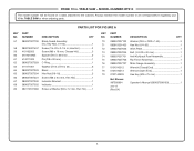
RYOBI 10 in , Cheese Hd 3 21 0101010304 Upper Pivot...Knife 1 48 089037007024 Clamp Bracket 1 49 089037007096 Spreader/Riving Knife Spring 1 50 089037007709 Riving Knife Handle Assembly 1 51 089037007912 Outer Guard Warning Label 1 52 089037007908 Warning Label (Upper Barrier 1 53 089037007911 Inner ... 20 410162701 Screw (1/4-20 x 3/4 in . Right 1 56 089037007910 Blade Guard Warning Label - Left 1 3 TABLE SAW or when ordering parts. Always mention the model number in all correspondence regarding your 10 in. PARTS LIST FOR FIGURE ...
RYOBI 10 in , Cheese Hd 3 21 0101010304 Upper Pivot...Knife 1 48 089037007024 Clamp Bracket 1 49 089037007096 Spreader/Riving Knife Spring 1 50 089037007709 Riving Knife Handle Assembly 1 51 089037007912 Outer Guard Warning Label 1 52 089037007908 Warning Label (Upper Barrier 1 53 089037007911 Inner ... 20 410162701 Screw (1/4-20 x 3/4 in . Right 1 56 089037007910 Blade Guard Warning Label - Left 1 3 TABLE SAW or when ordering parts. Always mention the model number in all correspondence regarding your 10 in. PARTS LIST FOR FIGURE ...
Parts Diagram
Page 4
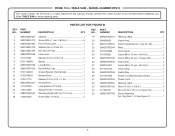
RYOBI 10 in . PARTS LIST FOR FIGURE A KEY PART NO. MODEL NUMBER RTS10 The model number will be found on a label attached to the cabinet. Always mention the model number in all correspondence regarding your 10 in . TABLE SAW - TABLE SAW or when ...20 1 72 089037007036 Work Plate 1 73 089037007035 Bolt (1/4-20 x 40 mm 1 74 089037007701 Anti-Kickback Pawl Assembly 1 75 089037007706 Rip Fence Assembly 1 76 089037007707 Miter Gauge Assembly 1 77 0101010312 Wrench (Closed End 1 78 0101010313 Wrench (Open End 1 79 0101140903 Hex Key (M5 x ...
RYOBI 10 in . PARTS LIST FOR FIGURE A KEY PART NO. MODEL NUMBER RTS10 The model number will be found on a label attached to the cabinet. Always mention the model number in all correspondence regarding your 10 in . TABLE SAW - TABLE SAW or when ...20 1 72 089037007036 Work Plate 1 73 089037007035 Bolt (1/4-20 x 40 mm 1 74 089037007701 Anti-Kickback Pawl Assembly 1 75 089037007706 Rip Fence Assembly 1 76 089037007707 Miter Gauge Assembly 1 77 0101010312 Wrench (Closed End 1 78 0101010313 Wrench (Open End 1 79 0101140903 Hex Key (M5 x ...
Parts Diagram
Page 6
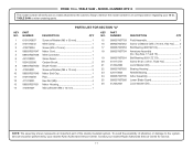
TABLE SAW - TABLE SAW or when ordering parts. PARTS LIST FOR FIGURE B KEY PART NO. NUMBER DESCRIPTION QTY 1 089037007037 Cabinet 1 2 080015001473 Screw (M4 x 7 mm, Flat Hd 6 3 089037007904 Front ... Screw (M4 x 18 mm 4 19 089037007901 Warning Label 1 20 984406003 Switch Key 1 21 089110109712 Switch Assembly (Inc. Key Nos. 1-8, See Figure C 1 6 RYOBI 10 in 4 34 411062701 Nut (1/4-20 x 10 mm, Cheese Hd 4 35 089037007708 Stand Assembly (Inc. MODEL NUMBER RTS10 The model number will be found on a label attached to the cabinet...
TABLE SAW - TABLE SAW or when ordering parts. PARTS LIST FOR FIGURE B KEY PART NO. NUMBER DESCRIPTION QTY 1 089037007037 Cabinet 1 2 080015001473 Screw (M4 x 7 mm, Flat Hd 6 3 089037007904 Front ... Screw (M4 x 18 mm 4 19 089037007901 Warning Label 1 20 984406003 Switch Key 1 21 089110109712 Switch Assembly (Inc. Key Nos. 1-8, See Figure C 1 6 RYOBI 10 in 4 34 411062701 Nut (1/4-20 x 10 mm, Cheese Hd 4 35 089037007708 Stand Assembly (Inc. MODEL NUMBER RTS10 The model number will be found on a label attached to the cabinet...
Parts Diagram
Page 11
... (D5 2 NOTE: The assembly shown represents an important part of alteration or damage to the system, service should be found on a label attached to the cabinet. Contact your nearest Ryobi Authorized Service Center. PARTS LIST FOR SECTION "A" KEY PART NO. To avoid the possibility of the double insulated system. TABLE SAW - MODEL NUMBER RTS10...
... (D5 2 NOTE: The assembly shown represents an important part of alteration or damage to the system, service should be found on a label attached to the cabinet. Contact your nearest Ryobi Authorized Service Center. PARTS LIST FOR SECTION "A" KEY PART NO. To avoid the possibility of the double insulated system. TABLE SAW - MODEL NUMBER RTS10...
Parts Diagram 1
Page 3
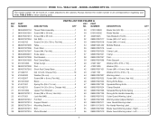
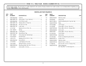
TABLE SAW - TABLE SAW or when ordering parts. NUMBER DESCRIPTION QTY 1 089040002704 Throat Plate Assembly 1 2 089015001001 Screw (M8 x 30 mm 1 3 089015001013 Screw (M8 x 35 mm 1 4 089037007004 Nut (M8 2 5 410102702 Screw (1/4-20 x 7/8 in, Flat Hd 4 6 089037007005 Table 1 7 089037007006 Push Stick 1 8 089037007007 Screw (M4, Pan Hd 2 9 089040002901 Scale Label 1 10 089037007008 Rod Bracket 1...DESCRIPTION QTY NO. MODEL NUMBER RTS10G The model number will be found on a label attached to the cabinet. Left 1 3 RYOBI 10 in.
TABLE SAW - TABLE SAW or when ordering parts. NUMBER DESCRIPTION QTY 1 089040002704 Throat Plate Assembly 1 2 089015001001 Screw (M8 x 30 mm 1 3 089015001013 Screw (M8 x 35 mm 1 4 089037007004 Nut (M8 2 5 410102702 Screw (1/4-20 x 7/8 in, Flat Hd 4 6 089037007005 Table 1 7 089037007006 Push Stick 1 8 089037007007 Screw (M4, Pan Hd 2 9 089040002901 Scale Label 1 10 089037007008 Rod Bracket 1...DESCRIPTION QTY NO. MODEL NUMBER RTS10G The model number will be found on a label attached to the cabinet. Left 1 3 RYOBI 10 in.

Parts Diagram 1
Page 4
... a label attached to the cabinet. NUMBER DESCRIPTION QTY 57 089037007700 Blade Guard Assembly (Inc. TABLE SAW or when ordering parts. Always mention the model number in all correspondence regarding ...TABLE SAW - PARTS LIST FOR FIGURE A KEY PART NO. Key Nos. 51-56 1 58 080015001437 Screw (1/4-20 x 3-1/4 in . RYOBI 10 in. NUMBER DESCRIPTION QTY 70 089037007102 Washer (D6.5 x D20 x 1.6t 3 71 080015001455 Hex Nut (1/4-20 1 72 089037007036 Work Plate 1 73 089037007035 Bolt (1/4-20 x 40 mm 1 74 089037007701 Anti-Kickback Pawl Assembly...
... a label attached to the cabinet. NUMBER DESCRIPTION QTY 57 089037007700 Blade Guard Assembly (Inc. TABLE SAW or when ordering parts. Always mention the model number in all correspondence regarding ...TABLE SAW - PARTS LIST FOR FIGURE A KEY PART NO. Key Nos. 51-56 1 58 080015001437 Screw (1/4-20 x 3-1/4 in . RYOBI 10 in. NUMBER DESCRIPTION QTY 70 089037007102 Washer (D6.5 x D20 x 1.6t 3 71 080015001455 Hex Nut (1/4-20 1 72 089037007036 Work Plate 1 73 089037007035 Bolt (1/4-20 x 40 mm 1 74 089037007701 Anti-Kickback Pawl Assembly...
Parts Diagram 1
Page 6
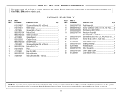
... NUMBER RTS10G The model number will be found on a label attached to the cabinet. Key Nos. 1-8, See Figure C 1 6 RYOBI 10 in . NUMBER DESCRIPTION QTY KEY PART NO. NUMBER DESCRIPTION QTY 1 089040002002 Cabinet 1 2 080015001473 Screw (M4 x 7 mm,...M4 x 18 mm 4 19 089037007901 Warning Label 1 20 984406003 Switch Key 1 21 089110109712 Switch Assembly (Inc. Always mention the model number in all correspondence regarding your 10 in . TABLE SAW or when ordering parts. Key No. 20 1 22 089037007044 Plate 1 23 0101040203 Cord Clamp ...
... NUMBER RTS10G The model number will be found on a label attached to the cabinet. Key Nos. 1-8, See Figure C 1 6 RYOBI 10 in . NUMBER DESCRIPTION QTY KEY PART NO. NUMBER DESCRIPTION QTY 1 089040002002 Cabinet 1 2 080015001473 Screw (M4 x 7 mm,...M4 x 18 mm 4 19 089037007901 Warning Label 1 20 984406003 Switch Key 1 21 089110109712 Switch Assembly (Inc. Always mention the model number in all correspondence regarding your 10 in . TABLE SAW or when ordering parts. Key No. 20 1 22 089037007044 Plate 1 23 0101040203 Cord Clamp ...
Parts Diagram 1
Page 11
... (6201RSZ C3, SRL/P6Z3V3)....... 1 20 410174721 Screw (8-32 x 3/8 in . RYOBI 10 in all correspondence regarding your nearest Ryobi Authorized Service Center for service. 11 TABLE SAW or when ordering parts. To avoid the possibility of the double insulated system. MODEL ... 14 412061001 Wavy Washer (M6 x 16 mm 1 15 089037007703 Field Assembly 1 16 089037007052 Screw w/Washer (M5 x 70 mm, Hex Hd.)........ 2 17 089040002009 Ball Bearing (6001-2RS 1 18 089037007704 Armature Assembly (Inc. Contact your 10 in , Truss Hd 1 21 412042002 Lock ...
... (6201RSZ C3, SRL/P6Z3V3)....... 1 20 410174721 Screw (8-32 x 3/8 in . RYOBI 10 in all correspondence regarding your nearest Ryobi Authorized Service Center for service. 11 TABLE SAW or when ordering parts. To avoid the possibility of the double insulated system. MODEL ... 14 412061001 Wavy Washer (M6 x 16 mm 1 15 089037007703 Field Assembly 1 16 089037007052 Screw w/Washer (M5 x 70 mm, Hex Hd.)........ 2 17 089040002009 Ball Bearing (6001-2RS 1 18 089037007704 Armature Assembly (Inc. Contact your 10 in , Truss Hd 1 21 412042002 Lock ...

