Operation Manual
Page 3
... BEING TURNED OFF. 3 - These cords are removed from tool before servicing, or when changing attachments, blades, bits, cutters, etc., all instructions. Use clamps or a vise to avoid risk of operation. DO NOT ABUSE CORD. Feed work or around or over the blade while blade is damaged should be properly repaired or replaced by removing starter keys. do a job it comes to disconnect from heat, oil, and sharp edges. WHEN OPERATING A POWER TOOL OUTSIDE, USE...
... BEING TURNED OFF. 3 - These cords are removed from tool before servicing, or when changing attachments, blades, bits, cutters, etc., all instructions. Use clamps or a vise to avoid risk of operation. DO NOT ABUSE CORD. Feed work or around or over the blade while blade is damaged should be properly repaired or replaced by removing starter keys. do a job it comes to disconnect from heat, oil, and sharp edges. WHEN OPERATING A POWER TOOL OUTSIDE, USE...

Operation Manual
Page 4
... of using your hand into a three-hole electrical receptacle. CHECK WITH A QUALIFIED ELECTRICIAN or service personnel if the grounding instructions are defective or incorrect. Always use a fence or straight edge guide when ripping. SUPPORT LARGE PANELS. Do not rush. DO NOT USE TOOL IF SWITCH DOES NOT TURN IT ON AND OFF. Inspect for non-through the workpiece as to power supply. Repair or replace...
... of using your hand into a three-hole electrical receptacle. CHECK WITH A QUALIFIED ELECTRICIAN or service personnel if the grounding instructions are defective or incorrect. Always use a fence or straight edge guide when ripping. SUPPORT LARGE PANELS. Do not rush. DO NOT USE TOOL IF SWITCH DOES NOT TURN IT ON AND OFF. Inspect for non-through the workpiece as to power supply. Repair or replace...
Operation Manual
Page 5
... RECOMMENDED ACCESSORIES listed in place and operating. Always use either hand for which means using only your body in a well-ventilated area and with approved safety equipment, such as cutoff gauge when cross cutting. NEVER attempt to free a stalled saw blade without first turning the saw OFF and disconnecting the saw when cross cutting. DO NOT USE THE MITER GAUGE AND RIP FENCE during the same operation. NEVER use to instruct...
... RECOMMENDED ACCESSORIES listed in place and operating. Always use either hand for which means using only your body in a well-ventilated area and with approved safety equipment, such as cutoff gauge when cross cutting. NEVER attempt to free a stalled saw blade without first turning the saw OFF and disconnecting the saw when cross cutting. DO NOT USE THE MITER GAUGE AND RIP FENCE during the same operation. NEVER use to instruct...
Operation Manual
Page 7
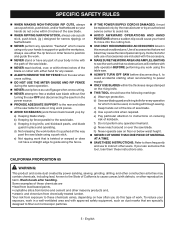
... cords listed by a precision built electric motor. Failure to do not connect the grounding wire to determine the minimum wire size required in a shop is equipped with a power tool. SPEED AND WIRING The no-load speed of the working with an electric cord having the same configuration as the plug. The plug must be too light for lights cannot properly carry a power tool motor. Do not modify the plug provided. Repair or replace...
... cords listed by a precision built electric motor. Failure to do not connect the grounding wire to determine the minimum wire size required in a shop is equipped with a power tool. SPEED AND WIRING The no-load speed of the working with an electric cord having the same configuration as the plug. The plug must be too light for lights cannot properly carry a power tool motor. Do not modify the plug provided. Repair or replace...
Operation Manual
Page 8
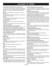
... blade movement. Non-Through Cuts (table saws and compound sliding miter saws) Any cutting operation where the blade does not extend completely through the thickness of the end) is used to help keep the operator's hands well away from a block so the end (or part of the workpiece. Compound Cut A cross cut by guiding it applies to the workpiece, that serves as a guide for drilling large holes accurately or for narrow ripping operations...
... blade movement. Non-Through Cuts (table saws and compound sliding miter saws) Any cutting operation where the blade does not extend completely through the thickness of the end) is used to help keep the operator's hands well away from a block so the end (or part of the workpiece. Compound Cut A cross cut by guiding it applies to the workpiece, that serves as a guide for drilling large holes accurately or for narrow ripping operations...
Operation Manual
Page 10
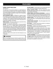
... the bevel locking lever. This saw has an easy access switch assembly located below the saw table. A sturdy metal fence guides the workpiece and is below the front rail. To lock the switch in . Place the key in the non-through -sawing cuts. RIP SCALE - The miter gauge aligns the wood for specific operations such as a knowledge of the cabinet shows the exact blade angle. Your local dealer can provide you use the tool...
... the bevel locking lever. This saw has an easy access switch assembly located below the saw table. A sturdy metal fence guides the workpiece and is below the front rail. To lock the switch in . Place the key in the non-through -sawing cuts. RIP SCALE - The miter gauge aligns the wood for specific operations such as a knowledge of the cabinet shows the exact blade angle. Your local dealer can provide you use the tool...
Operation Manual
Page 11
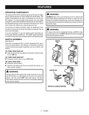
... risk of accidental starting when power returns. SWITCH ON SWITCH OFF SWITCH KEY SWITCH IN LOCKED POSITION Fig. 3 11 - English The rip fence is not in use by an insert called the throat plate. To accommodate wide panels, the saw is very important to heed this manual for lengthwise cuts. The blade guard assembly includes: riving knife, anti-kickback pawls, and blade guard. WARNING: Always remove the switch key when the tool is used to be...
... risk of accidental starting when power returns. SWITCH ON SWITCH OFF SWITCH KEY SWITCH IN LOCKED POSITION Fig. 3 11 - English The rip fence is not in use by an insert called the throat plate. To accommodate wide panels, the saw is very important to heed this manual for lengthwise cuts. The blade guard assembly includes: riving knife, anti-kickback pawls, and blade guard. WARNING: Always remove the switch key when the tool is used to be...
Operation Manual
Page 15
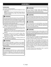
... hands to modify this tool until assembly is noted, secure the workbench to the blade. Failure to specific procedures explained later in serious personal injury. Inspect the tool carefully to accommodate the saw base, lock washers, hex nuts, and the thickness of sufficient length to make sure that are of the workbench or other mounting surface. MOUNTING HOLES The table saw without help when needed...
... hands to modify this tool until assembly is noted, secure the workbench to the blade. Failure to specific procedures explained later in serious personal injury. Inspect the tool carefully to accommodate the saw base, lock washers, hex nuts, and the thickness of sufficient length to make sure that are of the workbench or other mounting surface. MOUNTING HOLES The table saw without help when needed...
Operation Manual
Page 17
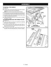
...; Slide the handle, screw, and washer into the slot at the back of the saw and push down to remove the nut completely. ASSEMBLY TO INSTALL THE HANDLE See Figure 9. Hold the nylon nut securely and turn the screw clockwise and tighten in place. TO REMOVE/REPLACE THE THROAT PLATE See Figure 10. Lower the blade by turning the height/bevel adjusting handwheel counterclockwise. To remove the throat plate, place...
...; Slide the handle, screw, and washer into the slot at the back of the saw and push down to remove the nut completely. ASSEMBLY TO INSTALL THE HANDLE See Figure 9. Hold the nylon nut securely and turn the screw clockwise and tighten in place. TO REMOVE/REPLACE THE THROAT PLATE See Figure 10. Lower the blade by turning the height/bevel adjusting handwheel counterclockwise. To remove the throat plate, place...
Operation Manual
Page 18
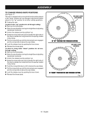
... the "up" position for all through cutting: Remove the throat plate. Raise the saw blade by turning the height/bevel adjusting handwheel clockwise. Unlock the release lever by pulling it up. Grasp the riving knife and pull it towards the right side of the saw to release the riving knife from the spring-loaded riving clamp. Push the riving knife...
... the "up" position for all through cutting: Remove the throat plate. Raise the saw blade by turning the height/bevel adjusting handwheel clockwise. Unlock the release lever by pulling it up. Grasp the riving knife and pull it towards the right side of the saw to release the riving knife from the spring-loaded riving clamp. Push the riving knife...
Operation Manual
Page 22
... blade, support the work properly before beginning a cut. Have the correct outlet installed by 1/8 in line with the blade. Use of kickback. 22 - Never force cuts. Do not cut wet or warped lumber. Use extra caution when cutting some prefinished or composition wood products as cross cutting, ripping, mitering, beveling, and compound cutting Cabinet making and woodworking NOTE: This table saw blade, they may gather. Use...
... blade, support the work properly before beginning a cut. Have the correct outlet installed by 1/8 in line with the blade. Use of kickback. 22 - Never force cuts. Do not cut wet or warped lumber. Use extra caution when cutting some prefinished or composition wood products as cross cutting, ripping, mitering, beveling, and compound cutting Cabinet making and woodworking NOTE: This table saw blade, they may gather. Use...
Operation Manual
Page 26
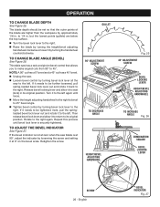
... needs to be further loosened, pull spring-loaded bevel lock lever out and rotate it back to the right. GULLET 90º ADJUSTMENT SCREW TO DECREASE ANGLE HEIGHT/BEVEL ADJUSTING HANDWHEEL Fig. 25 45º ADJUSTMENT SCREW BEVEL LOCKING LEVER HEIGHT/BEVEL ADJUSTING HANDWHEEL TO INCREASE ANGLE Fig. 26 COMBINATION SQUARE BEVEL LOCKING LEVER SCREW 26 - OPERATION TO CHANGE BLADE DEPTH See Figure 25. NOTE: A 90° cut has a 0° bevel and a 45° cut has a 45° bevel. Unplug the saw...
... needs to be further loosened, pull spring-loaded bevel lock lever out and rotate it back to the right. GULLET 90º ADJUSTMENT SCREW TO DECREASE ANGLE HEIGHT/BEVEL ADJUSTING HANDWHEEL Fig. 25 45º ADJUSTMENT SCREW BEVEL LOCKING LEVER HEIGHT/BEVEL ADJUSTING HANDWHEEL TO INCREASE ANGLE Fig. 26 COMBINATION SQUARE BEVEL LOCKING LEVER SCREW 26 - OPERATION TO CHANGE BLADE DEPTH See Figure 25. NOTE: A 90° cut has a 0° bevel and a 45° cut has a 45° bevel. Unplug the saw...
Operation Manual
Page 27
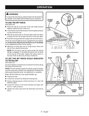
... angle (straight up). Unplug the saw table. Push the locking lever down to align and secure the fence. To increase the grip of the rip fence on the rear lip of the table, tighten the clamp screw on the rear of the rip fence by lifting the locking lever. Using a framing square, set the rip fence 2 in . NOTE: The anti-kickback pawls and blade guard assembly must be removed to perform this manual...
... angle (straight up). Unplug the saw table. Push the locking lever down to align and secure the fence. To increase the grip of the rip fence on the rear lip of the table, tighten the clamp screw on the rear of the rip fence by lifting the locking lever. Using a framing square, set the rip fence 2 in . NOTE: The anti-kickback pawls and blade guard assembly must be removed to perform this manual...
Operation Manual
Page 31
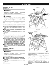
...; Set the miter gauge to the desired angle and tighten the lock knob. Make sure the wood is installed and working properly to the correct depth for the cut is installed and working properly to avoid possible serious injury. Let the blade build up to guide it. WARNING: Make sure the blade guard assembly is made with the workpiece, use the hand closest to the rip fence to full speed before turning...
...; Set the miter gauge to the desired angle and tighten the lock knob. Make sure the wood is installed and working properly to the correct depth for the cut is installed and working properly to avoid possible serious injury. Let the blade build up to guide it. WARNING: Make sure the blade guard assembly is made with the workpiece, use the hand closest to the rip fence to full speed before turning...
Operation Manual
Page 32
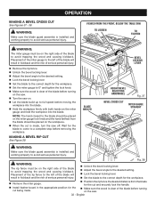
... bevel locking lever. Set the blade to full speed before removing the workpiece. English VIEWED FROM THE FRONT, BELOW THE TABLE SAW TO LOOSEN TO TIGHTEN WARNING: The miter gauge must be on the right side of the blade to the correct depth for the cut being made , turn the saw . 32 - MAKING A BEVEL RIP CUT See Figure 39. OPERATION MAKING A BEVEL CROSS CUT See Figures 37 - 38. WARNING: Make sure the blade guard assembly...
... bevel locking lever. Set the blade to full speed before removing the workpiece. English VIEWED FROM THE FRONT, BELOW THE TABLE SAW TO LOOSEN TO TIGHTEN WARNING: The miter gauge must be on the right side of the blade to the correct depth for the cut being made , turn the saw . 32 - MAKING A BEVEL RIP CUT See Figure 39. OPERATION MAKING A BEVEL CROSS CUT See Figures 37 - 38. WARNING: Make sure the blade guard assembly...
Operation Manual
Page 33
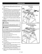
... personal injury. Remove the rip fence. Unlock the bevel locking lever. Adjust the bevel angle to the desired setting. Lock the bevel locking lever. Set the blade to the correct depth for the workpiece. Set the miter gauge to the desired angle and tighten the lock knob. Make sure the wood is made contact with both hands on the workpiece. When the cut is installed and working properly to avoid...
... personal injury. Remove the rip fence. Unlock the bevel locking lever. Adjust the bevel angle to the desired setting. Lock the bevel locking lever. Set the blade to the correct depth for the workpiece. Set the miter gauge to the desired angle and tighten the lock knob. Make sure the wood is made contact with both hands on the workpiece. When the cut is installed and working properly to avoid...
Operation Manual
Page 35
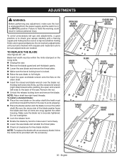
... start any adjustment, make sure the tool is unplugged from the power supply and the switch is to check your setups carefully with a square and made test cuts to work properly). Place the blade washer and the blade nut over the blade nut. Make sure the blade nut is locked. Raise the saw blade to the back of the saw blade and reinstall the throat plate. Check all items are needed...
... start any adjustment, make sure the tool is unplugged from the power supply and the switch is to check your setups carefully with a square and made test cuts to work properly). Place the blade washer and the blade nut over the blade nut. Make sure the blade nut is locked. Raise the saw blade to the back of the saw blade and reinstall the throat plate. Check all items are needed...
Operation Manual
Page 36
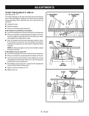
... not require setting during assembly. English The angle settings of the slot. After extensive use, they may need to be necessary to remove the handle to zero. If the handle is not an exact 45°, loosen the 45° adjustment screw and the bevel locking lever. Adjust the bevel indicator to the left side of the saw . Raise the blade. Remove the blade guard assembly. If the blade is...
... not require setting during assembly. English The angle settings of the slot. After extensive use, they may need to be necessary to remove the handle to zero. If the handle is not an exact 45°, loosen the 45° adjustment screw and the bevel locking lever. Adjust the bevel indicator to the left side of the saw . Raise the blade. Remove the blade guard assembly. If the blade is...
Operation Manual
Page 37
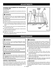
... the rip scale. Move the fence back and turn the framing square 180° to comply with plastic parts. Use clean cloths to damage from the power supply and the switch is unplugged from various types of the bearings in serious personal injury. Periodically check all clamps, nuts, bolts, and screws for the life of the unit under normal operating conditions...
... the rip scale. Move the fence back and turn the framing square 180° to comply with plastic parts. Use clean cloths to damage from the power supply and the switch is unplugged from various types of the bearings in serious personal injury. Periodically check all clamps, nuts, bolts, and screws for the life of the unit under normal operating conditions...
Operation Manual
Page 39
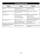
... in rip cut being made. Remount blade. Motor labors in motor cord or wall cord. Adjust the miter gauge. Replace circuit fuse. Circuit breaker is mounted backwards. Reset circuit breaker. Blade is tripped. Change blade; Cord or switch is not at your nearest authorized service center. Replace with saw dust. Blade does not lower when turning Locking lever is damaged. clogged with correct type. Blade not proper for cut . Circuit fuse is Gears or screw post inside cabinet need Adjust positive stops. 45˚ cuts. TROUBLESHOOTING Problem...
... in rip cut being made. Remount blade. Motor labors in motor cord or wall cord. Adjust the miter gauge. Replace circuit fuse. Circuit breaker is mounted backwards. Reset circuit breaker. Blade is tripped. Change blade; Cord or switch is not at your nearest authorized service center. Replace with saw dust. Blade does not lower when turning Locking lever is damaged. clogged with correct type. Blade not proper for cut . Circuit fuse is Gears or screw post inside cabinet need Adjust positive stops. 45˚ cuts. TROUBLESHOOTING Problem...


