English Manual
Page 4
...SAFETY RULES INSPECT TOOL CORDS PERIODICALLY. If repair or replacement of personal injury. If it well away from the rear of the planer. DO NOT ATTEMPT TO PERFORM an abnormal or little used operation without yellow stripes is properly grounded. USE ONLY CORRECT... WORKPIECE through the machine. If damaged, have the proper outlet installed by an authorized service center. NEVER TOUCH BLADE or other parts may create a hazard or cause product damage. USE ONLY RECOMMENDED ACCESSORIES listed in . MAINTAIN THE PROPER RELATIONSHIP between...
...SAFETY RULES INSPECT TOOL CORDS PERIODICALLY. If repair or replacement of personal injury. If it well away from the rear of the planer. DO NOT ATTEMPT TO PERFORM an abnormal or little used operation without yellow stripes is properly grounded. USE ONLY CORRECT... WORKPIECE through the machine. If damaged, have the proper outlet installed by an authorized service center. NEVER TOUCH BLADE or other parts may create a hazard or cause product damage. USE ONLY RECOMMENDED ACCESSORIES listed in . MAINTAIN THE PROPER RELATIONSHIP between...
English Manual
Page 5
...and other masonry products, and • arsenic and chromium from the power source and have damaged, missing, or failed parts replaced before using your planer. ALWAYS TURN OFF TOOL before disconnecting it, to avoid accidental starting when reconnecting to power supply. ... that a careless fraction of your exposure to avoid risk. SAVE THESE INSTRUCTIONS. Some examples of work using the planer. REPLACEMENT PARTS. All repairs, whether electrical or mechanical, should any work . WARNING: Some dust created by an authorized service center to ...
...and other masonry products, and • arsenic and chromium from the power source and have damaged, missing, or failed parts replaced before using your planer. ALWAYS TURN OFF TOOL before disconnecting it, to avoid accidental starting when reconnecting to power supply. ... that a careless fraction of your exposure to avoid risk. SAVE THESE INSTRUCTIONS. Some examples of work using the planer. REPLACEMENT PARTS. All repairs, whether electrical or mechanical, should any work . WARNING: Some dust created by an authorized service center to ...
English Manual
Page 9
...than at either end of the end) is angled rather than the blade, which helps keep the operator's hands well away from the blade. Snipe (planers) Depression made at 90°. Worktable Surface where the workpiece rests while performing a cutting, drilling, planing, or sanding operation. 9 GLOSSARY OF TERMS...strokes per minute), used to feed the workpiece through the saw blade tooth is bent (or set) outward from a block so the end (or part of a workpiece by guiding it applies to the table surface. Push Blocks and Push Sticks Devices used in a workpiece that serves as a guide...
...than at either end of the end) is angled rather than the blade, which helps keep the operator's hands well away from the blade. Snipe (planers) Depression made at 90°. Worktable Surface where the workpiece rests while performing a cutting, drilling, planing, or sanding operation. 9 GLOSSARY OF TERMS...strokes per minute), used to feed the workpiece through the saw blade tooth is bent (or set) outward from a block so the end (or part of a workpiece by guiding it applies to the table surface. Push Blocks and Push Sticks Devices used in a workpiece that serves as a guide...
English Manual
Page 11
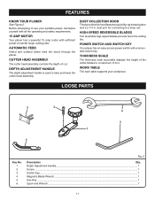
... raise and lower the cutter head assembly. WORK TABLE The work table supports your portable planer, familiarize yourself with all the operating and safety requirements. 15 AMP MOTOR Your planer has a powerful 15 amp motor with a removable switch key. HIGH-SPEED REVERSIBLE BLADES ...Two reversible high-speed blades provide twice the cutting life. LOOSE PARTS 3 2 6 5 1 4 Key No. 1 2 3 4 5 6 Fig. 3 Description Qty. DEPTH...
... raise and lower the cutter head assembly. WORK TABLE The work table supports your portable planer, familiarize yourself with all the operating and safety requirements. 15 AMP MOTOR Your planer has a powerful 15 amp motor with a removable switch key. HIGH-SPEED REVERSIBLE BLADES ...Two reversible high-speed blades provide twice the cutting life. LOOSE PARTS 3 2 6 5 1 4 Key No. 1 2 3 4 5 6 Fig. 3 Description Qty. DEPTH...
English Manual
Page 13
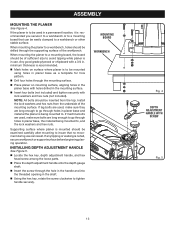
... INSTALLING DEPTH ADJUSTMENT HANDLE See Figure 5. Locate the hex key, depth adjustment handle, and hex head screw among the loose parts. Place the depth adjustment handle onto the depth gauge shaft. Insert the screw through the supporting surface of sufficient ...size to tighten handle securely. minimum thickness is recommended. Mark holes on mounting surface, aligning holes in the planer base with holes drilled in the mounting surface. Insert four bolts (not included) and tighten securely with a 3/4 in. If...
... INSTALLING DEPTH ADJUSTMENT HANDLE See Figure 5. Locate the hex key, depth adjustment handle, and hex head screw among the loose parts. Place the depth adjustment handle onto the depth gauge shaft. Insert the screw through the supporting surface of sufficient ...size to tighten handle securely. minimum thickness is recommended. Mark holes on mounting surface, aligning holes in the planer base with holes drilled in the mounting surface. Insert four bolts (not included) and tighten securely with a 3/4 in. If...
English Manual
Page 18
... various types of high grade lubricant for removal. GENERAL MAINTENANCE Avoid using solvents when cleaning plastic parts. of any maintenance or adjustment. If operation is required. Using the planer table as a mirror, touch the threaded spindle on or in this tool are permanently lubricated...cause possible serious personal injury, turn off the tool, remove the switch key, and unplug the planer before performing any other parts may result in place; TO REPLACE: Unplug the planer and remove the switch key. Lower the cutter head assembly. Remove the...
... various types of high grade lubricant for removal. GENERAL MAINTENANCE Avoid using solvents when cleaning plastic parts. of any maintenance or adjustment. If operation is required. Using the planer table as a mirror, touch the threaded spindle on or in this tool are permanently lubricated...cause possible serious personal injury, turn off the tool, remove the switch key, and unplug the planer before performing any other parts may result in place; TO REPLACE: Unplug the planer and remove the switch key. Lower the cutter head assembly. Remove the...
English Manual
Page 19
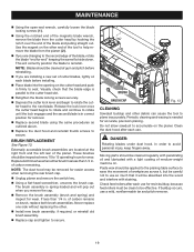
... open-end wrench, carefully loosen the blade locking screws ( 1 ). Using the notched end of the magnetic blade wrench, remove the blade from the planer ( 2 ). If you remove the cap. Remove the brush assembly (brush and spring) and inspect for wear. BRUSH BRUSH CAP Fig....not to use for accurate, precision planing. Clean the dust hood after each use a mild, nonflammable tar and pitch remover. 19 Moving parts should be applied to the planing table surface to seat. Check feed rollers after each use so much that the blade edge is spring-...
... open-end wrench, carefully loosen the blade locking screws ( 1 ). Using the notched end of the magnetic blade wrench, remove the blade from the planer ( 2 ). If you remove the cap. Remove the brush assembly (brush and spring) and inspect for wear. BRUSH BRUSH CAP Fig....not to use for accurate, precision planing. Clean the dust hood after each use a mild, nonflammable tar and pitch remover. 19 Moving parts should be applied to the planing table surface to seat. Check feed rollers after each use so much that the blade edge is spring-...
English Manual
Page 22
OPERATOR'S MANUAL 13 in the space provided below. • HOW TO ORDER REPAIR PARTS When ordering repair parts, always give the following information: • MODEL NUMBER AP1301 • SERIAL NUMBER Ryobi® is a registered trademark of Authorized Service Centers. • MODEL NO. Please ...purchased your tool, should a need ever exist for your nearest Authorized Service Center. PORTABLE PLANER AP1301 • SERVICE Now that you call 1-800-525-2579 for repair parts or service, simply contact your nearest Authorized Service Center. Be sure to the motor housing....
OPERATOR'S MANUAL 13 in the space provided below. • HOW TO ORDER REPAIR PARTS When ordering repair parts, always give the following information: • MODEL NUMBER AP1301 • SERIAL NUMBER Ryobi® is a registered trademark of Authorized Service Centers. • MODEL NO. Please ...purchased your tool, should a need ever exist for your nearest Authorized Service Center. PORTABLE PLANER AP1301 • SERVICE Now that you call 1-800-525-2579 for repair parts or service, simply contact your nearest Authorized Service Center. Be sure to the motor housing....
Repair Sheet
Page 3
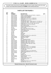
MODEL NUMBER AP1301 The model number will be found on a... mm HEX SOC 1 * WASHER (Ø8 X Ø18 X 2t 1 * Standard Hardware Item - RYOBI 13 in all correspondence regarding your PLANER or when ordering repair parts. HANDLE ASSEMBLY (INC. May Be Purchased Locally 3 PLANER - BUTTON HD 4 * SCREW (M5 X P0.8 X 8 mm PAN HD 3 DUST CHUTE PLATE ...35 36 37 38 39 40 41 42 43 44 45 46 47 PARTS LIST FOR FIGURE A PART NUMBER 089170101800 089170101001 089170101002 089170101003 089170101008 089170101010 089170101011 089170101012 089170101013 089170101014 089170101015 089170101016 ...
MODEL NUMBER AP1301 The model number will be found on a... mm HEX SOC 1 * WASHER (Ø8 X Ø18 X 2t 1 * Standard Hardware Item - RYOBI 13 in all correspondence regarding your PLANER or when ordering repair parts. HANDLE ASSEMBLY (INC. May Be Purchased Locally 3 PLANER - BUTTON HD 4 * SCREW (M5 X P0.8 X 8 mm PAN HD 3 DUST CHUTE PLATE ...35 36 37 38 39 40 41 42 43 44 45 46 47 PARTS LIST FOR FIGURE A PART NUMBER 089170101800 089170101001 089170101002 089170101003 089170101008 089170101010 089170101011 089170101012 089170101013 089170101014 089170101015 089170101016 ...
Repair Sheet
Page 4
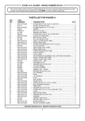
...RESET DIAL 1 LARGE COVER (RIGHT SIDE 1 SCALE LENGTH 1 LOGO LABEL 1 MOTOR/SWITCH ASSEMBLY (INC. RIGHT 2 BEARING BLOCK (23 mm 4 R.H. SPINDLE 1 BASE 1 L.H. MODEL NUMBER AP1301 The model number will be found on a plate attached to the motor housing. HD 2 CHAIN 1 SIDE COVER LABEL 2 * WASHER (Ø10.5 X Ø21 X 2t 4 ...WASHER 1 WRENCH (M8 X M10 1 HEX KEY (M4 X 120 mm 1 BLADE WRENCH 1 MOTOR WARNING LABEL 1 * Standard Hardware Item - May Be Purchased Locally 4 RYOBI 13 in all correspondence regarding your PLANER or when ordering repair parts.
...RESET DIAL 1 LARGE COVER (RIGHT SIDE 1 SCALE LENGTH 1 LOGO LABEL 1 MOTOR/SWITCH ASSEMBLY (INC. RIGHT 2 BEARING BLOCK (23 mm 4 R.H. SPINDLE 1 BASE 1 L.H. MODEL NUMBER AP1301 The model number will be found on a plate attached to the motor housing. HD 2 CHAIN 1 SIDE COVER LABEL 2 * WASHER (Ø10.5 X Ø21 X 2t 4 ...WASHER 1 WRENCH (M8 X M10 1 HEX KEY (M4 X 120 mm 1 BLADE WRENCH 1 MOTOR WARNING LABEL 1 * Standard Hardware Item - May Be Purchased Locally 4 RYOBI 13 in all correspondence regarding your PLANER or when ordering repair parts.
Repair Sheet
Page 6
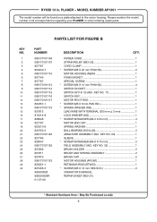
MODEL NUMBER AP1301 The model number will be found on a plate attached to the...INC. KEY NO. 20 1 SLEEVE 1 * SCREW W/WASHER (M4.8 X 75 mm 2 FIELD ASSEMBLY (INC. RYOBI 13 in all correspondence regarding your PLANER or when ordering repair parts. KEY NO. 11 1 SWITCH KEY 1 MOTOR PIVOT ROD 1 * SCREW (M5 X 8 mm PAN HD ... 12 13 14 15 16 17 18 19 20 21 22 23 24 25 26 27 28 29 30 PARTS LIST FOR FIGURE B PART NUMBER 089170101106 089170101107 827767 820240-7 089170101110 827740 827797 089170101113 089170101114 089170101115 089170101116 089170101117 820257-1 089170101119 827812 813314-8 828946...
MODEL NUMBER AP1301 The model number will be found on a plate attached to the...INC. KEY NO. 20 1 SLEEVE 1 * SCREW W/WASHER (M4.8 X 75 mm 2 FIELD ASSEMBLY (INC. RYOBI 13 in all correspondence regarding your PLANER or when ordering repair parts. KEY NO. 11 1 SWITCH KEY 1 MOTOR PIVOT ROD 1 * SCREW (M5 X 8 mm PAN HD ... 12 13 14 15 16 17 18 19 20 21 22 23 24 25 26 27 28 29 30 PARTS LIST FOR FIGURE B PART NUMBER 089170101106 089170101107 827767 820240-7 089170101110 827740 827797 089170101113 089170101114 089170101115 089170101116 089170101117 820257-1 089170101119 827812 813314-8 828946...


