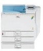
Hardware Guide
Page 1
For safe and correct use, be sure to the Printer 2 Installing Options 3 Connecting the Printer Cables 4 Configuration 5 Paper and Other Media 6 Replacing Consumables 7 Cleaning the Printer 8 Adjusting the Printer 9 Troubleshooting 10 Removing Misfed Paper 11 Appendix Read this machine and keep it handy for future reference. Operating Instructions Hardware Guide 1 Guide to read the Safety Information before you use this manual carefully before using the machine.
For safe and correct use, be sure to the Printer 2 Installing Options 3 Connecting the Printer Cables 4 Configuration 5 Paper and Other Media 6 Replacing Consumables 7 Cleaning the Printer 8 Adjusting the Printer 9 Troubleshooting 10 Removing Misfed Paper 11 Appendix Read this machine and keep it handy for future reference. Operating Instructions Hardware Guide 1 Guide to read the Safety Information before you use this manual carefully before using the machine.
Hardware Guide
Page 3
... Reading the LED Lamps...61 USB Cable Connection...62 Digital Camera Connection...63 1 Installing Options Available Options...21 Order of WARNING and CAUTION Labels 5 Manuals for This Printer...7 How to Read This Manual...8 Description for the Specified Model...9 Installing the Operating Instructions...10 1. Guide to the ...installing the Controller Board 26 Attaching the Optional Paper Feed Unit...27 Attaching the 500-sheet Paper Feed Unit to the Printer Exterior: Front View...11 Exterior: Rear View...13 Interior...15 Control Panel...17 Display Panel...19 Reading the Display and Using Keys......
... Reading the LED Lamps...61 USB Cable Connection...62 Digital Camera Connection...63 1 Installing Options Available Options...21 Order of WARNING and CAUTION Labels 5 Manuals for This Printer...7 How to Read This Manual...8 Description for the Specified Model...9 Installing the Operating Instructions...10 1. Guide to the ...installing the Controller Board 26 Attaching the Optional Paper Feed Unit...27 Attaching the 500-sheet Paper Feed Unit to the Printer Exterior: Front View...11 Exterior: Rear View...13 Interior...15 Control Panel...17 Display Panel...19 Reading the Display and Using Keys......
Hardware Guide
Page 4
Parallel Cable Connection...66 4. Configuration Ethernet Configuration...67 Specifying an IP Address (No DHCP)...68 Receiving an IP Address Automatically (DHCP 70 Configuring Network Settings When Using NetWare ... 3)...83 Bypass Tray...83 Paper Recommendations...86 Loading Paper...86 Storing Paper...86 Types of Paper and Other Media...86 Paper Not Supported by This Printer...95 Print Area...95 Loading Paper...97 Loading Paper into the Paper Tray, 500/1000-sheet Paper Feed Unit 97 Loading Paper into the 2000...
Parallel Cable Connection...66 4. Configuration Ethernet Configuration...67 Specifying an IP Address (No DHCP)...68 Receiving an IP Address Automatically (DHCP 70 Configuring Network Settings When Using NetWare ... 3)...83 Bypass Tray...83 Paper Recommendations...86 Loading Paper...86 Storing Paper...86 Types of Paper and Other Media...86 Paper Not Supported by This Printer...95 Print Area...95 Loading Paper...97 Loading Paper into the Paper Tray, 500/1000-sheet Paper Feed Unit 97 Loading Paper into the 2000...

Hardware Guide
Page 5
......155 Cleaning the Dustproof Glass...157 8. Adjusting the Printer Adjusting the Color Registration...159 Correcting the Color Gradation...161 Setting the Gradation Correction Value 161 Viewing the Color Calibration Sample Sheet and Gradation Correction Sheet 163 Resetting ...the Gradation Correction Value to the Initial Value 165 Adjusting Printing Position...167 9. Troubleshooting Error and Status Messages Appears on the Control Panel 171 Panel Tones...174 Printer Does Not Print...175 Checking the Port Connection...
......155 Cleaning the Dustproof Glass...157 8. Adjusting the Printer Adjusting the Color Registration...159 Correcting the Color Gradation...161 Setting the Gradation Correction Value 161 Viewing the Color Calibration Sample Sheet and Gradation Correction Sheet 163 Resetting ...the Gradation Correction Value to the Initial Value 165 Adjusting Printing Position...167 9. Troubleshooting Error and Status Messages Appears on the Control Panel 171 Panel Tones...174 Printer Does Not Print...175 Checking the Port Connection...

Hardware Guide
Page 9
... can use to prevent data tampering or unauthorized use of the machine. Quick Installation Guide Contains procedures for removing the printer from its box, connecting it to a computer, and installing its security functions. To avoid injury and prevent damage to the machine, be... for administrators of the machine. Hardware Guide (this manual) Contains information about paper and procedures such as required. Manuals for This Printer Refer to each manual as installing options, replacing consumables, responding to error messages, and resolving jams. Software Guide Contains information about ...
... can use to prevent data tampering or unauthorized use of the machine. Quick Installation Guide Contains procedures for removing the printer from its box, connecting it to a computer, and installing its security functions. To avoid injury and prevent damage to the machine, be... for administrators of the machine. Hardware Guide (this manual) Contains information about paper and procedures such as required. Manuals for This Printer Refer to each manual as installing options, replacing consumables, responding to error messages, and resolving jams. Software Guide Contains information about ...
Hardware Guide
Page 15
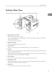
... holes. Replace it with the intermediate transfer unit together. 5. Optional Interface Board Slots Optional interface boards can be inserted. Power Connector Connect the power cable to prevent overheating. If humidity is moist due to high humidity, the print quality may decrease. Ventilator Releases heat... so results in the paper tray is high, turn the switch on the display. Ethernet Port Use a network interface cable to connect the printer to install options such as the SDRAM module or User Account Enhance Unit. 4. Replace the dustproof filter when the "Replacement Alert/...
... holes. Replace it with the intermediate transfer unit together. 5. Optional Interface Board Slots Optional interface boards can be inserted. Power Connector Connect the power cable to prevent overheating. If humidity is moist due to high humidity, the print quality may decrease. Ventilator Releases heat... so results in the paper tray is high, turn the switch on the display. Ethernet Port Use a network interface cable to connect the printer to install options such as the SDRAM module or User Account Enhance Unit. 4. Replace the dustproof filter when the "Replacement Alert/...

Hardware Guide
Page 16
Guide to a host computer. 1 14 1. USB Port Use a USB cable to connect the printer to the Printer 8.
Guide to a host computer. 1 14 1. USB Port Use a USB cable to connect the printer to the Printer 8.

Hardware Guide
Page 20
Press this to the initial screen. 18 While configuring settings, press the [Online] key to return to switch between online and offline status. Guide to the Printer 11. [Online] Key Indicates whether the printer is offline, disabling data reception from connected computers. 1 When the lamp is unlit, the printer is online or offline. When the lamp is lit, the printer is online, enabling data reception from the connected computers. 1.
Press this to the initial screen. 18 While configuring settings, press the [Online] key to return to switch between online and offline status. Guide to the Printer 11. [Online] Key Indicates whether the printer is offline, disabling data reception from connected computers. 1 When the lamp is unlit, the printer is online or offline. When the lamp is lit, the printer is online, enabling data reception from the connected computers. 1.

Hardware Guide
Page 35
... turn on the configuration page. Tighten the screws firmly using the remaining screws. On the rear of the tray, and slide it carefully into the printer until it cannot be displayed: • 500-sheet paper feed unit: Single Tray • 1000-sheet paper feed unit: Twin Trays • 2000-sheet paper... feed unit: LCT • If the tray was correctly attached, print the configuration page, and check "Connection Equipment" on the printer. 13. Attaching the Optional Paper Feed Unit 10. If it stops. 2 ASZ257S 11.
... turn on the configuration page. Tighten the screws firmly using the remaining screws. On the rear of the tray, and slide it carefully into the printer until it cannot be displayed: • 500-sheet paper feed unit: Single Tray • 1000-sheet paper feed unit: Twin Trays • 2000-sheet paper... feed unit: LCT • If the tray was correctly attached, print the configuration page, and check "Connection Equipment" on the printer. 13. Attaching the Optional Paper Feed Unit 10. If it stops. 2 ASZ257S 11.

Hardware Guide
Page 39
... the five screws. Fasten the controller board to the printer. 8. Attaching the SDRAM Module 2 ATU008S 7. ATU009S Push it firmly into the printer, and push it carefully in "Device Connection" on the configuration page. 37 Check that the SDRAM module was correctly installed by printing the configuration page. ATU010S • Confirm that the total...
... the five screws. Fasten the controller board to the printer. 8. Attaching the SDRAM Module 2 ATU008S 7. ATU009S Push it firmly into the printer, and push it carefully in "Device Connection" on the configuration page. 37 Check that the SDRAM module was correctly installed by printing the configuration page. ATU010S • Confirm that the total...

Hardware Guide
Page 44
Fasten the controller board to the printer using the five screws. 2 ATU010S • Confirm that the user account enhance unit was correctly installed by returning unneeded user account enhance units to your ... the configuration page. If it is not installed properly, repeat the procedure from step 2. 2. See p.26 "Cautions When Re-installing the Controller Board" for "Device Connection" on the configuration page. • If the user account enhance unit is correctly installed, "Accounting Module" will appear for details. • "Test Printing", Quick Installation...
Fasten the controller board to the printer using the five screws. 2 ATU010S • Confirm that the user account enhance unit was correctly installed by returning unneeded user account enhance units to your ... the configuration page. If it is not installed properly, repeat the procedure from step 2. 2. See p.26 "Cautions When Re-installing the Controller Board" for "Device Connection" on the configuration page. • If the user account enhance unit is correctly installed, "Accounting Module" will appear for details. • "Test Printing", Quick Installation...
Hardware Guide
Page 45
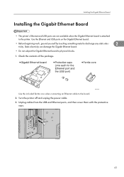
...to discharge any static elec- 2 tricity. ATU001S Use the included ferrite core when connecting an Ethernet cable to the printer. Installing the Gigabit Ethernet Board Installing the Gigabit Ethernet Board • The printer's Ethernet and USB ports are not available when the Gigabit Ethernet board is attached... to the board. 2. Unplug cables from the USB and Ethernet ports, and then cover them with the protective caps. Turn the printer off and unplug the power cable...
...to discharge any static elec- 2 tricity. ATU001S Use the included ferrite core when connecting an Ethernet cable to the printer. Installing the Gigabit Ethernet Board Installing the Gigabit Ethernet Board • The printer's Ethernet and USB ports are not available when the Gigabit Ethernet board is attached... to the board. 2. Unplug cables from the USB and Ethernet ports, and then cover them with the protective caps. Turn the printer off and unplug the power cable...

Hardware Guide
Page 46
Loosen the two screws and remove the slot cover. 2 ATU023S The removed cover will appear for "Device Connection" on the configuration page. 44 Tighten the two screws to the controller board. 6. If it is firmly connected to secure the board. Fully insert the Gigabit Ethernet board. ATU015S Confirm that the Gigabit Ethernet board was correctly installed by printing the configuration page. ATU018S • Confirm that the Gigabit Ethernet board is correctly installed, "Gigabit Ethernet Board" will not be reused. 5. 2. Installing Options 4.
Loosen the two screws and remove the slot cover. 2 ATU023S The removed cover will appear for "Device Connection" on the configuration page. 44 Tighten the two screws to the controller board. 6. If it is firmly connected to secure the board. Fully insert the Gigabit Ethernet board. ATU015S Confirm that the Gigabit Ethernet board was correctly installed by printing the configuration page. ATU018S • Confirm that the Gigabit Ethernet board is correctly installed, "Gigabit Ethernet Board" will not be reused. 5. 2. Installing Options 4.
Hardware Guide
Page 47
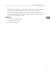
See p.67 "Ethernet Configuration" for details. 2 • "Test Printing", Quick Installation Guide • p.59 "Ethernet Cable Connection" • p.67 "Ethernet Configuration" 45 If it cannot be installed correctly even after reattempting installation, contact your sales or service representative. • For information on ... board, you must configure settings from step 2. Installing the Gigabit Ethernet Board • If the board was not installed properly, repeat the procedure from the printer control panel.
See p.67 "Ethernet Configuration" for details. 2 • "Test Printing", Quick Installation Guide • p.59 "Ethernet Cable Connection" • p.67 "Ethernet Configuration" 45 If it cannot be installed correctly even after reattempting installation, contact your sales or service representative. • For information on ... board, you must configure settings from step 2. Installing the Gigabit Ethernet Board • If the board was not installed properly, repeat the procedure from the printer control panel.

Hardware Guide
Page 49
Attach the antenna to secure the interface unit. Attach them so that the interface unit is facing up. Fully insert the interface unit. AET096S 47 ATU018S 6. Installing the IEEE 802.11b Interface Unit 2 ATU017S Confirm that the label of the card is facing down, and the ridged side of the antenna is firmly connected to the controller board. 5. Tighten the two screws to the card. 4.
Attach the antenna to secure the interface unit. Attach them so that the interface unit is facing up. Fully insert the interface unit. AET096S 47 ATU018S 6. Installing the IEEE 802.11b Interface Unit 2 ATU017S Confirm that the label of the card is facing down, and the ridged side of the antenna is firmly connected to the controller board. 5. Tighten the two screws to the card. 4.

Hardware Guide
Page 50
... it stops. 2 ATU019S 8. ATU020S • Confirm that the interface unit was not installed properly, repeat the procedure from the printer control panel. 2. See p.76 "IEEE 802.11b (Wireless LAN) Configuration" for "Device Connection" on printing the configuration page, see "Test Printing", Quick Installation Guide. • "Test Printing", Quick Installation Guide • p.76...
... it stops. 2 ATU019S 8. ATU020S • Confirm that the interface unit was not installed properly, repeat the procedure from the printer control panel. 2. See p.76 "IEEE 802.11b (Wireless LAN) Configuration" for "Device Connection" on printing the configuration page, see "Test Printing", Quick Installation Guide. • "Test Printing", Quick Installation Guide • p.76...

Hardware Guide
Page 52
Fully insert the interface unit. 2 ATU017S Confirm that the label on both the card and adapter is firmly connected to the controller board. 5. ATU018S 6. Installing Options 4. Tighten the two screws to the card adapter. 2. Attach them so that the interface unit is facing up. 50 ASZ032S Attach the card to secure the interface unit.
Fully insert the interface unit. 2 ATU017S Confirm that the label on both the card and adapter is firmly connected to the controller board. 5. ATU018S 6. Installing Options 4. Tighten the two screws to the card adapter. 2. Attach them so that the interface unit is facing up. 50 ASZ032S Attach the card to secure the interface unit.

Hardware Guide
Page 53
If it is correctly installed, "Bluetooth" will appear for "Device Connection" on printing the configuration page, see the operating instructions included with the Bluetooth interface unit. • For information on the configuration page. • If the ...
If it is correctly installed, "Bluetooth" will appear for "Device Connection" on printing the configuration page, see the operating instructions included with the Bluetooth interface unit. • For information on the configuration page. • If the ...

Hardware Guide
Page 54
... the two screws and remove the slot cover. Turn the printer off and unplug the power cable. 3. 2. Static electricity can damage the IEEE 1284 interface board. 2 • Do not subject the IEEE 1284 interface board to physical shocks. • For connection to discharge any static electricity. ATU023S The removed cover will not...
... the two screws and remove the slot cover. Turn the printer off and unplug the power cable. 3. 2. Static electricity can damage the IEEE 1284 interface board. 2 • Do not subject the IEEE 1284 interface board to physical shocks. • For connection to discharge any static electricity. ATU023S The removed cover will not...

Hardware Guide
Page 55
...step 2. Tighten the two screws to the controller board. 5. Fully insert the IEEE 1284 interface board. If it is firmly connected to secure the interface board. 4. ATU025S • Confirm that the IEEE 1284 interface board is correctly installed, "Parallel Interface" will appear... page, see "Test Printing", Quick Installation Guide. • "Test Printing", Quick Installation Guide • p.66 "Parallel Cable Connection". 53 If it cannot be installed correctly even after reattempting installation, contact your sales or service representative. • For information on...
...step 2. Tighten the two screws to the controller board. 5. Fully insert the IEEE 1284 interface board. If it is firmly connected to secure the interface board. 4. ATU025S • Confirm that the IEEE 1284 interface board is correctly installed, "Parallel Interface" will appear... page, see "Test Printing", Quick Installation Guide. • "Test Printing", Quick Installation Guide • p.66 "Parallel Cable Connection". 53 If it cannot be installed correctly even after reattempting installation, contact your sales or service representative. • For information on...


