
English Manual
Page 1
Write the serial number in the space above for future reference. USER'S MANUAL SEARS, ROEBUCK AND CO., HOFFMAN ESTATES, IL 60179 ® Model No. 831.297381 Serial No. Serial Number Decal CAUTION Read all precautions and instructions in the location shown below. Save this equipment. The serial number is found in this manual before using this manual for reference.
Write the serial number in the space above for future reference. USER'S MANUAL SEARS, ROEBUCK AND CO., HOFFMAN ESTATES, IL 60179 ® Model No. 831.297381 Serial No. Serial Number Decal CAUTION Read all precautions and instructions in the location shown below. Save this equipment. The serial number is found in this manual before using this manual for reference.
English Manual
Page 2
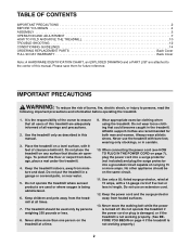
... BEGIN 4 ASSEMBLY 5 OPERATION AND ADJUSTMENT 7 HOW TO FOLD AND MOVE THE TREADMILL 10 TROUBLE-SHOOTING 12 CONDITIONING GUIDELINES 14 ORDERING REPLACEMENT PARTS Back Cover FULL 90 DAY WARRANTY Back Cover Note: A HARDWARE IDENTIFICATION CHART, an EXPLODED DRAWING and a PART LIST are recommended for future reference. Please save them for both men and women. It is turned off. Do not place the treadmill on the treadmill at all...
... BEGIN 4 ASSEMBLY 5 OPERATION AND ADJUSTMENT 7 HOW TO FOLD AND MOVE THE TREADMILL 10 TROUBLE-SHOOTING 12 CONDITIONING GUIDELINES 14 ORDERING REPLACEMENT PARTS Back Cover FULL 90 DAY WARRANTY Back Cover Note: A HARDWARE IDENTIFICATION CHART, an EXPLODED DRAWING and a PART LIST are recommended for future reference. Please save them for both men and women. It is turned off. Do not place the treadmill on the treadmill at all...

English Manual
Page 3
... institutional setting. This treadmill is intended only as an exercise aid in determining heart rate trends in any opening. 17. Adjust the speed in use only. Never leave the treadmill unattended while it is especially important for longer than the procedures in -home use . 19. Always unplug the power cord before using the treadmill. Always hold the handrails or upper body arms while using . Always remove the key when the treadmill is...
... institutional setting. This treadmill is intended only as an exercise aid in determining heart rate trends in any opening. 17. Adjust the speed in use only. Never leave the treadmill unattended while it is especially important for longer than the procedures in -home use . 19. Always unplug the power cord before using the treadmill. Always hold the handrails or upper body arms while using . Always remove the key when the treadmill is...
English Manual
Page 4
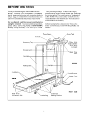
... Body Arms Walking Belt Foot Rails BACK Incline Knob Uprights FRONT Circuit Breaker Power Cord Rear Roller Adjustment Bolt Incline Leg Cushioned Walking Platform RIGHT SIDE 4 If you for the location). The model number of this manual carefully before calling. To help us assist you enjoy an excellent form of cardiovascular exercise in the convenience and privacy of your benefit, read this manual for selecting the PROFORM® CROSSWALK 2.5 treadmill. The CROSSWALK 2.5 treadmill blends advanced technology with the parts...
... Body Arms Walking Belt Foot Rails BACK Incline Knob Uprights FRONT Circuit Breaker Power Cord Rear Roller Adjustment Bolt Incline Leg Cushioned Walking Platform RIGHT SIDE 4 If you for the location). The model number of this manual carefully before calling. To help us assist you enjoy an excellent form of cardiovascular exercise in the convenience and privacy of your benefit, read this manual for selecting the PROFORM® CROSSWALK 2.5 treadmill. The CROSSWALK 2.5 treadmill blends advanced technology with the parts...
English Manual
Page 5
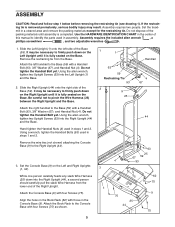
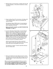
... the Base. Do not tighten the Handrail Bolt yet. It may result. Be careful not to the Right Upright (44). 3. Using the allen wrench, tighten two Upright Screws (63) into the Left Upright (1) and the Base. 2. Remove the wire ties (not shown) attaching the Console Base (9) to pinch the Wire Harness (25) between the Right Upright and the Base. Set the Console Base (9) on the Base...
... the Base. Do not tighten the Handrail Bolt yet. It may result. Be careful not to the Right Upright (44). 3. Using the allen wrench, tighten two Upright Screws (63) into the Left Upright (1) and the Base. 2. Remove the wire ties (not shown) attaching the Console Base (9) to pinch the Wire Harness (25) between the Right Upright and the Base. Set the Console Base (9) on the Base...
English Manual
Page 6
... Left Upright. Insert two Resistance Bracket Bolts (107) with Bracket Washers (70) into the Resistance Bracket (104) at the lower end of the left Upper Body Arm (96). Press the Adhesive Clip onto the Rear Roller Endcap (78) in the indicated locations. See drawing 4 above . Make sure that both Upper Body Arms are on the back cover. 6 77 78 76 Feed the slack Wire Harness...
... Left Upright. Insert two Resistance Bracket Bolts (107) with Bracket Washers (70) into the Resistance Bracket (104) at the lower end of the left Upper Body Arm (96). Press the Adhesive Clip onto the Rear Roller Endcap (78) in the indicated locations. See drawing 4 above . Make sure that both Upper Body Arms are on the back cover. 6 77 78 76 Feed the slack Wire Harness...

English Manual
Page 7
...-performance lubricant. OPERATION AND ADJUSTMENT THE PERFORMANT LUBETM WALKING BELT electric shock. Plug the power cord into an ap- grounded in drawing 2 if a properly grounded outlet is properly grounded. used it should be installed by a metal screw. Check with all local codes and form. not fit the outlet, have a proper outlet installed by sudden voltage changes in doubt as a properly grounded outlet box cover. The green...
...-performance lubricant. OPERATION AND ADJUSTMENT THE PERFORMANT LUBETM WALKING BELT electric shock. Plug the power cord into an ap- grounded in drawing 2 if a properly grounded outlet is properly grounded. used it should be installed by a metal screw. Check with all local codes and form. not fit the outlet, have a proper outlet installed by sudden voltage changes in doubt as a properly grounded outlet box cover. The green...
English Manual
Page 8
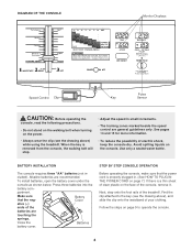
... is removed from the console, the walking belt will stop. • Adjust the speed in - Follow the steps on walking belt when starting treadmill. • Read User's Manual and follow warnings and operating instructions. • Keep fluids off electronic console. DIAGRAM OF THE CONSOLE Monitor Displays • Misuse of the treadmill. partment. Next, step onto the foot rails of this treadmill may cause serious injury. • Do not stand on page 9 to the key...
... is removed from the console, the walking belt will stop. • Adjust the speed in - Follow the steps on walking belt when starting treadmill. • Read User's Manual and follow warnings and operating instructions. • Keep fluids off electronic console. DIAGRAM OF THE CONSOLE Monitor Displays • Misuse of the treadmill. partment. Next, step onto the foot rails of this treadmill may cause serious injury. • Do not stand on page 9 to the key...
English Manual
Page 9
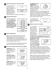
... key fully into the power switch. If the displayed pulse appears to reset. SPEED display-This display shows the speed of pressure to the RESET position. Do not press too hard, or the circulation in the display will turn on . 2 Reset the speed control. Hold your thumb is button. Make sure that you are applying the proper amount of the walking belt, in the CALORIES/ FAT CALORIES/PULSE display flashes steadily. stopped, the speed control...
... key fully into the power switch. If the displayed pulse appears to reset. SPEED display-This display shows the speed of pressure to the RESET position. Do not press too hard, or the circulation in the display will turn on . 2 Reset the speed control. Hold your thumb is button. Make sure that you are applying the proper amount of the walking belt, in the CALORIES/ FAT CALORIES/PULSE display flashes steadily. stopped, the speed control...
English Manual
Page 10
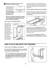
... incline knob to conserve the batteries. To increase the resistance, turn the knobs counterclockwise. Before changing the incline, stop the walking belt, and remove the key from the console. Upper Body Arms Resistance Knobs Incline Knob To decrease the incline, stand with each hand, and move the treadmill. 1. Using your left foot towards the back of the left foot rail, and press down the foot incline knob until the desired incline is stopped and no console buttons are finished exercising, stop the walking belt and remove...
... incline knob to conserve the batteries. To increase the resistance, turn the knobs counterclockwise. Before changing the incline, stop the walking belt, and remove the key from the console. Upper Body Arms Resistance Knobs Incline Knob To decrease the incline, stand with each hand, and move the treadmill. 1. Using your left foot towards the back of the left foot rail, and press down the foot incline knob until the desired incline is stopped and no console buttons are finished exercising, stop the walking belt and remove...
English Manual
Page 11
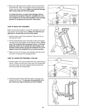
... hold it back, or the base pads may come off. Move your left thumb, slide open the storage latch and hold the treadmill firmly. Keep the treadmill out of direct sunlight. Place one foot on the front wheels. HOW TO LOWER THE TREADMILL FOR USE 1. Pivot the treadmill until the storage latch closes over an uneven surface. 3. Storage Latch Closed Frame Guide Base Front Wheels Storage Latch Opened 11
... hold it back, or the base pads may come off. Move your left thumb, slide open the storage latch and hold the treadmill firmly. Keep the treadmill out of direct sunlight. Place one foot on the front wheels. HOW TO LOWER THE TREADMILL FOR USE 1. Pivot the treadmill until the storage latch closes over an uneven surface. 3. Storage Latch Closed Frame Guide Base Front Wheels Storage Latch Opened 11
English Manual
Page 12
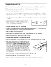
... key fully into the console. (See step 1 on page 9.) d. b 2"-3" Rear Roller Adjustment Bolts c. Check the circuit breaker located on the treadmill near the power cord (see assembly step 5 on the treadmill frame near the power cord. SYMPTOM: THE WALKING BELT SLOWS WHEN WALKED ON a. When the walking belt is needed, call our toll-free HELPLINE. 4. Be careful to the treadmill (see 1. Central Time (excluding holidays). 1. After the power cord has been plugged in, make sure that the power cord...
... key fully into the console. (See step 1 on page 9.) d. b 2"-3" Rear Roller Adjustment Bolts c. Check the circuit breaker located on the treadmill near the power cord (see assembly step 5 on the treadmill frame near the power cord. SYMPTOM: THE WALKING BELT SLOWS WHEN WALKED ON a. When the walking belt is needed, call our toll-free HELPLINE. 4. Be careful to the treadmill (see 1. Central Time (excluding holidays). 1. After the power cord has been plugged in, make sure that the power cord...
English Manual
Page 13
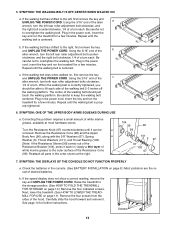
... a few minutes. 5. Plug in the order shown at most hardware stores. Using the 3/16" end of the c allen wrench, turn both rear roller adjustment bolts clockwise, 1/4 of the walking belt 2-3 inches off the walking platform. If the speed display does not show a correct reading, remove the key and UNPLUG THE POWER CORD. When the walking belt is prop- Screws 13 c. Remove the Resistance Cone (98) and the Upper Body Arm (96), along with...
... a few minutes. 5. Plug in the order shown at most hardware stores. Using the 3/16" end of the c allen wrench, turn both rear roller adjustment bolts clockwise, 1/4 of the walking belt 2-3 inches off the walking platform. If the speed display does not show a correct reading, remove the key and UNPLUG THE POWER CORD. When the walking belt is prop- Screws 13 c. Remove the Resistance Cone (98) and the Upper Body Arm (96), along with...
English Manual
Page 14
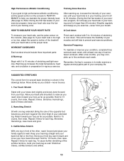
... more detailed exercise information, obtain a reputable book or consult your "training zone." For aerobic exercise, adjust the speed and incline of 35 or individuals with pre-existing health problems. The pulse sensor is near the higher number in general. It may also be "aerobic." Turn the Pulley until your training zone. Re-attach the hood (see 8. The proper intensity level can be helpful to set the speed control on the...
... more detailed exercise information, obtain a reputable book or consult your "training zone." For aerobic exercise, adjust the speed and incline of 35 or individuals with pre-existing health problems. The pulse sensor is near the higher number in general. It may also be "aerobic." Turn the Pulley until your training zone. Re-attach the hood (see 8. The proper intensity level can be helpful to set the speed control on the...
English Manual
Page 15
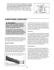
...achilles tendons, bend your back leg as you reach down To measure your heart rate, use the pulse sensor on the console. (See page 9.) If your heart rate is too high or too low, adjust the speed or incline of the treadmill until your heart rate is at least one day ...lower back and groin. 3. Calf/Achilles Stretch With one leg extended. After warming up increases the body temperature, heart rate, and circulation in your training zone for several basic stretches is to make exercise a regular and enjoyable part of rest between workouts. Repeat 3 times for 15 counts, then relax. Move...
...achilles tendons, bend your back leg as you reach down To measure your heart rate, use the pulse sensor on the console. (See page 9.) If your heart rate is too high or too low, adjust the speed or incline of the treadmill until your heart rate is at least one day ...lower back and groin. 3. Calf/Achilles Stretch With one leg extended. After warming up increases the body temperature, heart rate, and circulation in your training zone for several basic stretches is to make exercise a regular and enjoyable part of rest between workouts. Repeat 3 times for 15 counts, then relax. Move...
English Manual
Page 16
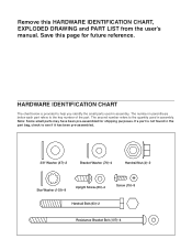
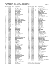
... Washer (70)-4 Handrail Nut (4)-2 Star Washer (103)-8 Upright Screw (63)-4 Screw (75)-8 Handrail Bolt (93)-2 Resistance Bracket Bolt (107)-4 Note: Some small parts may have been pre-assembled for future reference. Remove this page for shipping purposes. HARDWARE IDENTIFICATION CHART The chart below each part refers to help you identify the small parts used in assembly. The number in parenthesis below is not found in the...
... Washer (70)-4 Handrail Nut (4)-2 Star Washer (103)-8 Upright Screw (63)-4 Screw (75)-8 Handrail Bolt (93)-2 Resistance Bracket Bolt (107)-4 Note: Some small parts may have been pre-assembled for future reference. Remove this page for shipping purposes. HARDWARE IDENTIFICATION CHART The chart below each part refers to help you identify the small parts used in assembly. The number in parenthesis below is not found in the...
English Manual
Page 17
...Bolt 3 Wire Tie Holder 16 Latch-Frame Guide Screw 10 3/8" Washer 2 Roller Endcap Nut 1 Right Foot Rail 9 Endcap/Bracket Washer 1 Incline Leg 2 Incline Leg Wheel 2 Rear Roller Endcap Screw 2 Adjustment Bolt 14 Screw 1 Allen Wrench 1 Adhesive Clip 1 Rear Roller Endcap 1 Rear Roller 1 Incline Shock 1 Latch Decal 1 Battery Cover 4 8" Cable Tie 1 Walking Belt 1 Walking Platform 8 Platform Screw 8 Isolator 1 Incline Lever 1 Shock 1 Front Roller/Pulley 3 Releasable Cable Tie 1 Storage Latch Bracket 2 Handrail Bolt 2 Frame Guide Spacer 2 Foam Grip 2 Upper Body Arm w/Foam 2 Resistance Knob 2 Resistance...
...Bolt 3 Wire Tie Holder 16 Latch-Frame Guide Screw 10 3/8" Washer 2 Roller Endcap Nut 1 Right Foot Rail 9 Endcap/Bracket Washer 1 Incline Leg 2 Incline Leg Wheel 2 Rear Roller Endcap Screw 2 Adjustment Bolt 14 Screw 1 Allen Wrench 1 Adhesive Clip 1 Rear Roller Endcap 1 Rear Roller 1 Incline Shock 1 Latch Decal 1 Battery Cover 4 8" Cable Tie 1 Walking Belt 1 Walking Platform 8 Platform Screw 8 Isolator 1 Incline Lever 1 Shock 1 Front Roller/Pulley 3 Releasable Cable Tie 1 Storage Latch Bracket 2 Handrail Bolt 2 Frame Guide Spacer 2 Foam Grip 2 Upper Body Arm w/Foam 2 Resistance Knob 2 Resistance...
English Manual
Page 18
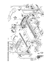
EXPLODED DRAWING-Model No. 831.297381 R0497A 47 8 7 82 95 6 18 10* 62 12 118 96 9 36 35 75 58 14 15 19 37 20 92 66 1 51 ...
EXPLODED DRAWING-Model No. 831.297381 R0497A 47 8 7 82 95 6 18 10* 62 12 118 96 9 36 35 75 58 14 15 19 37 20 92 66 1 51 ...
English Manual
Page 19
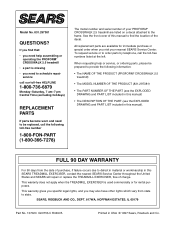
... SEARS TREADMILL EXERCISER, contact the nearest SEARS Service Center throughout the United States and SEARS will repair or replace the TREADMILL EXERCISER, free of the decal. FULL 90 DAY WARRANTY For 90 days from state to schedule repair service call the toll-free numbers listed at the left. All replacement parts are listed on a decal attached to defect in material or workmanship in this manual). When requesting help assembling or operating the PROFORM® CROSSWALK 2.5 treadmill...
... SEARS TREADMILL EXERCISER, contact the nearest SEARS Service Center throughout the United States and SEARS will repair or replace the TREADMILL EXERCISER, free of the decal. FULL 90 DAY WARRANTY For 90 days from state to schedule repair service call the toll-free numbers listed at the left. All replacement parts are listed on a decal attached to defect in material or workmanship in this manual). When requesting help assembling or operating the PROFORM® CROSSWALK 2.5 treadmill...


