

English Manual
Page 1
USER'S MANUAL CAUTION Read all precautions and instructions in the space above for future reference. If you have questions, or if parts are damaged or missing, CONTACT THE STORE WHERE YOU PURCHASED THIS PRODUCT. PIRW34008.0 Serial No. Keep this equipment. Model No. www.proform.com Serial Number Decal QUESTIONS? Write the serial number in this manual before using this manual for reference.
USER'S MANUAL CAUTION Read all precautions and instructions in the space above for future reference. If you have questions, or if parts are damaged or missing, CONTACT THE STORE WHERE YOU PURCHASED THIS PRODUCT. PIRW34008.0 Serial No. Keep this equipment. Model No. www.proform.com Serial Number Decal QUESTIONS? Write the serial number in this manual before using this manual for reference.
English Manual
Page 2
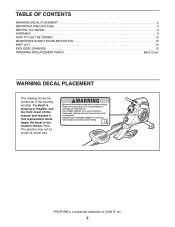
TABLE OF CONTENTS WARNING DECAL PLACEMENT 2 IMPORTANT PRECAUTIONS 3 BEFORE YOU BEGIN 4 ASSEMBLY 5 HOW TO USE THE ROWER 10 MAINTENANCE AND TROUBLESHOOTING 13 PART LIST 14 EXPLODED DRAWING 15 ORDERING REPLACEMENT PARTS Back Cover WARNING DECAL PLACEMENT This drawing shows the location(s) of ICON IP, Inc. 2 Apply the decal in the location shown. Note: The decal(s) may not be shown at actual size. PROFORM is missing or illegible, see the front cover of this manual and request a free replacement decal. If a decal is a registered trademark of the warning decal(s).
TABLE OF CONTENTS WARNING DECAL PLACEMENT 2 IMPORTANT PRECAUTIONS 3 BEFORE YOU BEGIN 4 ASSEMBLY 5 HOW TO USE THE ROWER 10 MAINTENANCE AND TROUBLESHOOTING 13 PART LIST 14 EXPLODED DRAWING 15 ORDERING REPLACEMENT PARTS Back Cover WARNING DECAL PLACEMENT This drawing shows the location(s) of ICON IP, Inc. 2 Apply the decal in the location shown. Note: The decal(s) may not be shown at actual size. PROFORM is missing or illegible, see the front cover of this manual and request a free replacement decal. If a decal is a registered trademark of the warning decal(s).
English Manual
Page 3
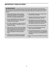
... wear athletic shoes for home use only. Inspect and properly tighten all users of the rower are adequately informed of the rower. 5. The rower is the responsibility of the owner to protect the floor or carpet. Keep your back straight while using your rower. Wear appropriate exercise clothes when exercising; Place the rower on a level surface, with pre-existing health problems. 2. Use the rower only as described in...
... wear athletic shoes for home use only. Inspect and properly tighten all users of the rower are adequately informed of the rower. 5. The rower is the responsibility of the owner to protect the floor or carpet. Keep your back straight while using your rower. Wear appropriate exercise clothes when exercising; Place the rower on a level surface, with pre-existing health problems. 2. Use the rower only as described in...
English Manual
Page 4
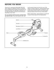
... after read this manual carefully before you , note the product model number and serial number before contacting us assist you use the rower. Handle Console Resistance Control Lock Knob Seat Footrest Frame Pin Stabilizer Pin 4 ing this manual, please see the front cover of this manual. If you for toning the body, strengthening the muscles, and building the cardiovascular system. The 980 ZLW is an effective exercise for selecting the PROFORM® 980 ZLW rower.
... after read this manual carefully before you , note the product model number and serial number before contacting us assist you use the rower. Handle Console Resistance Control Lock Knob Seat Footrest Frame Pin Stabilizer Pin 4 ing this manual, please see the front cover of this manual. If you for toning the body, strengthening the muscles, and building the cardiovascular system. The 980 ZLW is an effective exercise for selecting the PROFORM® 980 ZLW rower.
English Manual
Page 5
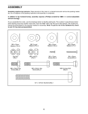
... adjustable As you assemble the rower, use the drawings below each drawing is the key number of the part, from the PART LIST near the end of this manual. M8 x 16mm Washer (75)-6 M8 Curved Washer (74)-2 M8 x 23mm Washer (76)-2 M8 x 26mm Washer (77)-1 Jam Nut (78)-1 M8 Locknut (73)-4 M3 x 12mm Screw (42)-2 M4 x 25mm Screw (84)-2 M8 x 15mm Hex Screw...
... adjustable As you assemble the rower, use the drawings below each drawing is the key number of the part, from the PART LIST near the end of this manual. M8 x 16mm Washer (75)-6 M8 Curved Washer (74)-2 M8 x 23mm Washer (76)-2 M8 x 26mm Washer (77)-1 Jam Nut (78)-1 M8 Locknut (73)-4 M3 x 12mm Screw (42)-2 M4 x 25mm Screw (84)-2 M8 x 15mm Hex Screw...

English Manual
Page 6
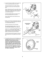
1. To make assembly easier, read the 1 information on the underside of the Frame (1), attach the Front Stabilizer (44) to the Frame (1) with two M8 Carriage Bolts (82), two M8 Curved Washers (74), and two M8 Locknuts (73). 2. While a second person lifts the front of the Frame. Attach the Footrest Bracket (46) to the Frame with two M8 x 55mm Hex Screws (83) and two M8 x 16mm Washers (75). 74 73 74 1 44 82 75 1 83 75 46 6 While a second person lifts the rear of the Frame (1), slide the Footrest Bracket (46) onto 2 the bracket on page 5 before you begin.
1. To make assembly easier, read the 1 information on the underside of the Frame (1), attach the Front Stabilizer (44) to the Frame (1) with two M8 Carriage Bolts (82), two M8 Curved Washers (74), and two M8 Locknuts (73). 2. While a second person lifts the front of the Frame. Attach the Footrest Bracket (46) to the Frame with two M8 x 55mm Hex Screws (83) and two M8 x 16mm Washers (75). 74 73 74 1 44 82 75 1 83 75 46 6 While a second person lifts the rear of the Frame (1), slide the Footrest Bracket (46) onto 2 the bracket on page 5 before you begin.

English Manual
Page 7
...Attach the Rear Stabilizer (62) to the Right and Left Shields (2, 3) with two M3 x 12mm Screws (42). 3 Avoid pinching the Extension Wire (90) 3 2 42 90 48 46 42 4. Tip: Avoid pinching the Extension Wire (90). Attach the Footrest Bracket Cover (48) to the underside of the Rail (49) with an M4 x 16mm Screws (84). 49 84 80 Press...Hex 5 Screws (86) and four M8 x 16mm Washers (75). 49 75 86 75 86 62 7 Orient the Seat (52) and the Rail (49) as shown. 3. Slide the Footrest Bracket Cover (48) onto the Footrest Bracket (46). Then, slide the Seat onto the Rail. 4 Attach a ...
...Attach the Rear Stabilizer (62) to the Right and Left Shields (2, 3) with two M3 x 12mm Screws (42). 3 Avoid pinching the Extension Wire (90) 3 2 42 90 48 46 42 4. Tip: Avoid pinching the Extension Wire (90). Attach the Footrest Bracket Cover (48) to the underside of the Rail (49) with an M4 x 16mm Screws (84). 49 84 80 Press...Hex 5 Screws (86) and four M8 x 16mm Washers (75). 49 75 86 75 86 62 7 Orient the Seat (52) and the Rail (49) as shown. 3. Slide the Footrest Bracket Cover (48) onto the Footrest Bracket (46). Then, slide the Seat onto the Rail. 4 Attach a ...
English Manual
Page 8
...- Press a Rest Pad (81) onto each end of the Rest Bar (69). 6 76 79 71 73 81 46 68 69 81 71 79 76 73 7. The Console (72) can use two AA batteries (not included); alkaline batteries are recommended. 8 IMPORTANT: If the Console has been 72 exposed to cold temperatures, allow it to warm to the Reed Switch Wire (41...
...- Press a Rest Pad (81) onto each end of the Rest Bar (69). 6 76 79 71 73 81 46 68 69 81 71 79 76 73 7. The Console (72) can use two AA batteries (not included); alkaline batteries are recommended. 8 IMPORTANT: If the Console has been 72 exposed to cold temperatures, allow it to warm to the Reed Switch Wire (41...
English Manual
Page 9
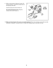
Note: Some hardware may be left over after assembly is completed. Make sure that all parts of the rower are properly tightened. While a second person holds the Console (72) near the Frame (1), connect the console wire to the Extension Wire (90). To protect the floor or carpet from damage, place a mat under the rower. 9 Press the Console (72) into the Frame (1). Tip: Avoid pinching the wires. 9. Insert the excess wire into the Frame (1). 9 72 1 Console 90 Wire Avoid pinching the wires 10.
Note: Some hardware may be left over after assembly is completed. Make sure that all parts of the rower are properly tightened. While a second person holds the Console (72) near the Frame (1), connect the console wire to the Extension Wire (90). To protect the floor or carpet from damage, place a mat under the rower. 9 Press the Console (72) into the Frame (1). Tip: Avoid pinching the wires. 9. Insert the excess wire into the Frame (1). 9 72 1 Console 90 Wire Avoid pinching the wires 10.

English Manual
Page 10
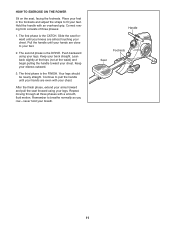
... unfold the rower, reverse the steps listed above. Remove the stabilizer pin and move the stabilizer downward until it is folded against the frame. Then, reinsert the frame pin. 3. IMPORTANT: Stop turning the knob when turning becomes difficult, or you may damage the rower. Reinsert the stabilizer pin. Lock Knob Rail Stabilizer Pin Stabilizer HOW TO ADJUST THE RESISTANCE To increase the resistance of the way. 1. Resistance Control Frame Pin 10 HOW TO USE...
... unfold the rower, reverse the steps listed above. Remove the stabilizer pin and move the stabilizer downward until it is folded against the frame. Then, reinsert the frame pin. 3. IMPORTANT: Stop turning the knob when turning becomes difficult, or you may damage the rower. Reinsert the stabilizer pin. Lock Knob Rail Stabilizer Pin Stabilizer HOW TO ADJUST THE RESISTANCE To increase the resistance of the way. 1. Resistance Control Frame Pin 10 HOW TO USE...
English Manual
Page 11
... the FINISH. Your legs should be nearly straight. Remember to fit your chest. Correct rowing form consists of three phases: 1. Pull the handle until your hands are even with your feet. 2. Continue to your chest. Push backward using your back straight. The third phase is the DRIVE. HOW TO EXERCISE ON THE ROWER Sit on the seat, facing the footrests...
... the FINISH. Your legs should be nearly straight. Remember to fit your chest. Correct rowing form consists of three phases: 1. Pull the handle until your hands are even with your feet. 2. Continue to your chest. Push backward using your back straight. The third phase is the DRIVE. HOW TO EXERCISE ON THE ROWER Sit on the seat, facing the footrests...
English Manual
Page 12
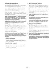
... Total Reset button was last pressed. When you have burned. Set a workout goal, if desired. Time-Displays the elapsed time. Next, press the Set button repeatedly to zero, press the Reset button while that batteries are installed (see step 3), this mode will provide instant feedback about your workout, press the Mode button repeatedly until the Time, Count, or Calories mode is selected. If you are not pressed for display. Note: Before using the console, make...
... Total Reset button was last pressed. When you have burned. Set a workout goal, if desired. Time-Displays the elapsed time. Next, press the Set button repeatedly to zero, press the Reset button while that batteries are installed (see step 3), this mode will provide instant feedback about your workout, press the Mode button repeatedly until the Time, Count, or Calories mode is selected. If you are not pressed for display. Note: Before using the console, make...
English Manual
Page 13
... UNFOLD THE ROWER on page 8 for battery installation instructions. Store the rower in a folded position to the console, keep liquids away from the console when storing the rower. 13 HOW TO STORE THE ROWER The rower can be replaced. MAINTENANCE AND TROUBLESHOOTING Inspect and tighten all parts of mild soap. CONSOLE TROUBLESHOOTING If the console does not function properly, the batteries should be stored in a location where children cannot tip it. See assembly step...
... UNFOLD THE ROWER on page 8 for battery installation instructions. Store the rower in a folded position to the console, keep liquids away from the console when storing the rower. 13 HOW TO STORE THE ROWER The rower can be replaced. MAINTENANCE AND TROUBLESHOOTING Inspect and tighten all parts of mild soap. CONSOLE TROUBLESHOOTING If the console does not function properly, the batteries should be stored in a location where children cannot tip it. See assembly step...

English Manual
Page 14
... Bolt 83 2 M8 x 55mm Hex Screw 84 7 M4 x 25mm Screw 85 1 M5 x 20mm Screw 86 6 M8 x 15mm Hex Screw 87 1 Frame Pin 88 1 1/2" x 127mm Hex Bolt 89 1 Rail Cap 90 1 Extension Wire * - PIRW34008.0 R0310A Key No. Qty. Assembly Tool Note: Specifications are not illustrated. 14 For information about ordering replacement parts, please see the back cover of this manual. *These parts are subject to change without notice. Userʼs Manual * - PART LIST-Model...
... Bolt 83 2 M8 x 55mm Hex Screw 84 7 M4 x 25mm Screw 85 1 M5 x 20mm Screw 86 6 M8 x 15mm Hex Screw 87 1 Frame Pin 88 1 1/2" x 127mm Hex Bolt 89 1 Rail Cap 90 1 Extension Wire * - PIRW34008.0 R0310A Key No. Qty. Assembly Tool Note: Specifications are not illustrated. 14 For information about ordering replacement parts, please see the back cover of this manual. *These parts are subject to change without notice. Userʼs Manual * - PART LIST-Model...

English Manual
Page 15
PIRW34008.0 R0310A 65 12 39 5 10 17 3 40 72 11 13 30 16 15 40 10 30 2 28 26 84 9 25 14 12 38 73 20 2324 32 38 18 65 84 40 27 29 43 4 6 7 8 73 7520 31 1920 33 20 32 33 75 2019 20 24 23 24 73 24 24 36 85 37 24 23 32 38 73 34 73 74 24 58 52 59 60 55 56 57 84 80 89 53 73 41 54 51 80 84 78 77 84 80 49 90 21 75 84 80 73 86 76 79 45 50 75 71 42 61 75 75 86 66 24 63 70 81 48 64 42 47 69 67 63 88 87 75 75 46 81 70 1 23 35 83 82 68 19 20 22 20 75 73 44 45 71 79 76 73 62 15 EXPLODED DRAWING-Model No.
PIRW34008.0 R0310A 65 12 39 5 10 17 3 40 72 11 13 30 16 15 40 10 30 2 28 26 84 9 25 14 12 38 73 20 2324 32 38 18 65 84 40 27 29 43 4 6 7 8 73 7520 31 1920 33 20 32 33 75 2019 20 24 23 24 73 24 24 36 85 37 24 23 32 38 73 34 73 74 24 58 52 59 60 55 56 57 84 80 89 53 73 41 54 51 80 84 78 77 84 80 49 90 21 75 84 80 73 86 76 79 45 50 75 71 42 61 75 75 86 66 24 63 70 81 48 64 42 47 69 67 63 88 87 75 75 46 81 70 1 23 35 83 82 68 19 20 22 20 75 73 44 45 71 79 76 73 62 15 EXPLODED DRAWING-Model No.

English Manual
Page 16
To help us assist you, please be prepared to provide the following information when contacting us: • the model number and serial number of the product (see the front cover of this manual) • the name of the product (see the front cover of this manual) • the key number and description of the replacement part(s) (see the front cover of this manual. ORDERING REPLACEMENT PARTS To order replacement parts, see the PART LIST and the EXPLODED DRAWING near the end of this manual) Part No. 282415 R0310A Printed in Taiwan © 2010 ICON IP, Inc.
To help us assist you, please be prepared to provide the following information when contacting us: • the model number and serial number of the product (see the front cover of this manual) • the name of the product (see the front cover of this manual) • the key number and description of the replacement part(s) (see the front cover of this manual. ORDERING REPLACEMENT PARTS To order replacement parts, see the PART LIST and the EXPLODED DRAWING near the end of this manual) Part No. 282415 R0310A Printed in Taiwan © 2010 ICON IP, Inc.


