
English Manual
Page 1
....-Fri., 6 a.m.-6 p.m. Model No. 831.288080 Serial No. MST CAUTION Read all precautions and instructions in this manual before using this manual for future reference. The trained technicians on our customer hot line will guarantee complete satisfaction through direct assistance from our factory. TO AVOID UNNECESSARY DELAYS, PLEASE CALL DIRECT TO OUR TOLL-FREE CUSTOMER HOT LINE. Keep this equipment. USER'S MANUAL Patent...
....-Fri., 6 a.m.-6 p.m. Model No. 831.288080 Serial No. MST CAUTION Read all precautions and instructions in this manual before using this manual for future reference. The trained technicians on our customer hot line will guarantee complete satisfaction through direct assistance from our factory. TO AVOID UNNECESSARY DELAYS, PLEASE CALL DIRECT TO OUR TOLL-FREE CUSTOMER HOT LINE. Keep this equipment. USER'S MANUAL Patent...
English Manual
Page 2
... with pre-existing health problems. Read all users of the recumbent cycle are adequately informed of heart rate readings. It is the responsibility of the owner to move until the flywheel stops. 11. The pulse sensor is intended for persons over the age of this manual before using . The pulse sensor is especially important for home use only. ICON assumes no responsibility for foot protection. 12. Replace any exercise program, consult your...
... with pre-existing health problems. Read all users of the recumbent cycle are adequately informed of heart rate readings. It is the responsibility of the owner to move until the flywheel stops. 11. The pulse sensor is intended for persons over the age of this manual before using . The pulse sensor is especially important for home use only. ICON assumes no responsibility for foot protection. 12. Replace any exercise program, consult your...
English Manual
Page 3
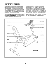
... Congratulations for increasing cardiovascular fitness, building endurance, and toning the entire body. The model number is one of your benefit, read this healthful exercise in the drawing below. until 6 p.m. Handlebar Pulse Sensor Book Holder Console Resistance Knob Backrest Seat REAR Seat Knob FRONT Pedal Strap Pedal Wheel RIGHT SIDE 3 The PROFORM® 955R offers an impressive array of features to the recumbent cycle (see the front cover of this manual). Before reading further...
... Congratulations for increasing cardiovascular fitness, building endurance, and toning the entire body. The model number is one of your benefit, read this healthful exercise in the drawing below. until 6 p.m. Handlebar Pulse Sensor Book Holder Console Resistance Knob Backrest Seat REAR Seat Knob FRONT Pedal Strap Pedal Wheel RIGHT SIDE 3 The PROFORM® 955R offers an impressive array of features to the recumbent cycle (see the front cover of this manual). Before reading further...
English Manual
Page 4
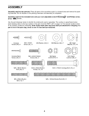
Place all parts of the recumbent cycle in assembly. Use the part drawings below each drawing refers to the quantity needed for shipping. The second number refers to the key number of the packing materials until assembly is completed. ASSEMBLY Assembly requires two persons. Do not dispose of the part, from the PART LIST on page 14. Console Screw (35)-4 M4 x 16mm Screw (21)-3 M6 Washer (54)-3 M8 Washer...
Place all parts of the recumbent cycle in assembly. Use the part drawings below each drawing refers to the quantity needed for shipping. The second number refers to the key number of the packing materials until assembly is completed. ASSEMBLY Assembly requires two persons. Do not dispose of the part, from the PART LIST on page 14. Console Screw (35)-4 M4 x 16mm Screw (21)-3 M6 Washer (54)-3 M8 Washer...
English Manual
Page 5
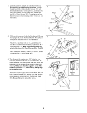
... avoid pinching the wires. Next, attach the Tension Control (22) to pinch the wires. 3 9 30 Hole 17 71 Batteries Battery Clip Wires 35 5 The Console (9) requires two "AA" batteries (not included). While another person holds the Handlebar (16) near the Upright (6), route the Reed Switch Wire (18) up through the Upright and into the battery clip as shown in the Handlebar. To install batteries, turn the console over and insert...
... avoid pinching the wires. Next, attach the Tension Control (22) to pinch the wires. 3 9 30 Hole 17 71 Batteries Battery Clip Wires 35 5 The Console (9) requires two "AA" batteries (not included). While another person holds the Handlebar (16) near the Upright (6), route the Reed Switch Wire (18) up through the Upright and into the battery clip as shown in the Handlebar. To install batteries, turn the console over and insert...

English Manual
Page 6
... the Handlebar (16) as shown. 4. Make sure that no wires are not touching the floor. 69 2 7. Identify the green console ground wire and attach it to the corresponding wires on 7 the Frame (1). Next, connect the Reed Switch Wire (18) and the two Pulse Wires (33) to the Handlebar with two M10 x 75mm Carriage Bolts (72) 72 and two M10 Nylon Locknuts (45).
... the Handlebar (16) as shown. 4. Make sure that no wires are not touching the floor. 69 2 7. Identify the green console ground wire and attach it to the corresponding wires on 7 the Frame (1). Next, connect the Reed Switch Wire (18) and the two Pulse Wires (33) to the Handlebar with two M10 x 75mm Carriage Bolts (72) 72 and two M10 Nylon Locknuts (45).

English Manual
Page 7
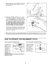
... four 24 M8 x 38mm Button Bolts (24). 27 24 8 11 10. Attach the Seat Frame and the 9 Backrest Frame to the Carriage Bar with two M6 x 38mm Button Bolts (14) and two M6 Nylon Locknuts (15). Attach the Seat (12) to the other side of the Backrest Frame (8). 15 11. 8. Hold the Rear Stabilizer (3) under the Carriage Bar 8 (7) in the position...
... four 24 M8 x 38mm Button Bolts (24). 27 24 8 11 10. Attach the Seat Frame and the 9 Backrest Frame to the Carriage Bar with two M6 x 38mm Button Bolts (14) and two M6 Nylon Locknuts (15). Attach the Seat (12) to the other side of the Backrest Frame (8). 15 11. 8. Hold the Rear Stabilizer (3) under the Carriage Bar 8 (7) in the position...
English Manual
Page 8
... Pedal (40). Place a mat beneath the recumbent cycle to decrease the resistance, turn the resistance knob clockwise; Tighten the Right Pedal (not shown) clockwise into the Left Crank Arm (19). tion and press the Pedal Strap onto the tab on the Left Pedal for one week, retighten the Pedals. Important: Stop turning the knob when turning becomes difficult or damage may be kept tightened. 13 41 40 Tab Adjust the Left Pedal Strap...
... Pedal (40). Place a mat beneath the recumbent cycle to decrease the resistance, turn the resistance knob clockwise; Tighten the Right Pedal (not shown) clockwise into the Left Crank Arm (19). tion and press the Pedal Strap onto the tab on the Left Pedal for one week, retighten the Pedals. Important: Stop turning the knob when turning becomes difficult or damage may be kept tightened. 13 41 40 Tab Adjust the Left Pedal Strap...
English Manual
Page 9
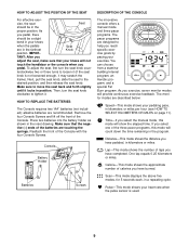
... handlebar or the console when you select the manual mode, this mode will show the elapsed time. As you reach specific exercise goals by pacing your heart rate when the pulse sensor is not loosened enough, it locks in the program. Lap-This mode shows the number of laps you select one of the batteries are recommended. Scan-This mode displays the above five modes, for 5 seconds...
... handlebar or the console when you select the manual mode, this mode will show the elapsed time. As you reach specific exercise goals by pacing your heart rate when the pulse sensor is not loosened enough, it locks in the program. Lap-This mode shows the number of laps you select one of the batteries are recommended. Scan-This mode displays the above five modes, for 5 seconds...
English Manual
Page 10
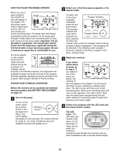
... three pacer programs or the manual mode. Adjust your actual exercising pace. The LED track-The LED track represents a distance of bars will appear in the display. STEP-BY-STEP CONSOLE OPERATION Before the console can be operated, two batteries must be on the console show which Program Button program you have completed one of the program. The program indicator will already be installed. (See BATTERY REPLACEMENT on page 12.) 1 Turn on /reset On/Reset button or sim...
... three pacer programs or the manual mode. Adjust your actual exercising pace. The LED track-The LED track represents a distance of bars will appear in the display. STEP-BY-STEP CONSOLE OPERATION Before the console can be operated, two batteries must be on the console show which Program Button program you have completed one of the program. The program indicator will already be installed. (See BATTERY REPLACEMENT on page 12.) 1 Turn on /reset On/Reset button or sim...
English Manual
Page 11
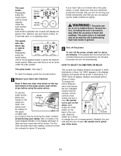
The speed, time, distance, lap, or calorie mode- WARNING: The pulse sen- sor is used, make sure that your hands are positioned correctly, that you are not moving your heart rate will be shown in general. 6 Turn off automatically. If the pedals are not moved and the console buttons are clear vinyl strips on the back of the wires. 11 tacts. The console can display distance and speed in...
The speed, time, distance, lap, or calorie mode- WARNING: The pulse sen- sor is used, make sure that your hands are positioned correctly, that you are not moving your heart rate will be shown in general. 6 Turn off automatically. If the pedals are not moved and the console buttons are clear vinyl strips on the back of the wires. 11 tacts. The console can display distance and speed in...
English Manual
Page 12
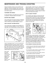
... be replaced. To replace the batteries, refer to the console, keep liquids away from the Crank (19). When the Reed Switch is straight and tighten the M8 Nylon Locknuts (56). Loosen but do this, the side shields must be removed. PULSE SENSOR TROUBLE-SHOOTING • Avoid moving your hands while using the pulse sensor. MAINTENANCE AND TROUBLE-SHOOTING Inspect and tighten all parts of the Flywheel (70). HOW TO ADJUST THE REED SWITCH...
... be replaced. To replace the batteries, refer to the console, keep liquids away from the Crank (19). When the Reed Switch is straight and tighten the M8 Nylon Locknuts (56). Loosen but do this, the side shields must be removed. PULSE SENSOR TROUBLE-SHOOTING • Avoid moving your hands while using the pulse sensor. MAINTENANCE AND TROUBLE-SHOOTING Inspect and tighten all parts of the Flywheel (70). HOW TO ADJUST THE REED SWITCH...
English Manual
Page 13
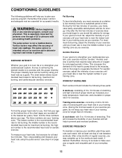
... heart rate for energy. Then, stop pedaling and measure your heart rate using your heart rate as you exercise. Remember, the key to success is especially important for fat burning; Various factors may complete up increases your body temperature, heart rate, and circulation in your training zone for a sustained period of rest between workouts. Only after the first few weeks of your exercise program, do not keep your heart rate...
... heart rate for energy. Then, stop pedaling and measure your heart rate using your heart rate as you exercise. Remember, the key to success is especially important for fat burning; Various factors may complete up increases your body temperature, heart rate, and circulation in your training zone for a sustained period of rest between workouts. Only after the first few weeks of your exercise program, do not keep your heart rate...
English Manual
Page 14
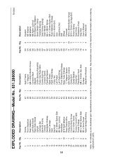
... replacement parts. 14 Description Key No. Qty. Specifications are subject to change without notice. Description Key No. Qty. Description 1 1 Frame 2 1 Front Stabilizer 3 1 Rear Stabilizer 4 1 Left Side Shield 5 1 Right Side Shield 6 1 Upright 7 1 Carriage Bar 8 1 Backrest Frame 9 1 Console 10 2 Handlebar Endcap 11 1 Seat Carriage 12 1 Seat 13 1 Backrest 14 7 M6 x 38mm Button Bolt 15 4 M6 Nylon Locknut 16 1 Handlebar 17 10 M10 Split Washer 18 1 Reed Switch/Wire 19 1 Pulley/Crank...
... replacement parts. 14 Description Key No. Qty. Specifications are subject to change without notice. Description Key No. Qty. Description 1 1 Frame 2 1 Front Stabilizer 3 1 Rear Stabilizer 4 1 Left Side Shield 5 1 Right Side Shield 6 1 Upright 7 1 Carriage Bar 8 1 Backrest Frame 9 1 Console 10 2 Handlebar Endcap 11 1 Seat Carriage 12 1 Seat 13 1 Backrest 14 7 M6 x 38mm Button Bolt 15 4 M6 Nylon Locknut 16 1 Handlebar 17 10 M10 Split Washer 18 1 Reed Switch/Wire 19 1 Pulley/Crank...
English Manual
Page 15
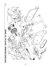
EXPLODED DRAWING-Model No. 831.288080 18 20 16 33 30 9 38 R1000A 60 15 6 17 71 37 10 61 71 17 17 71 19 24 75 17 71 17 71 69 72 69 45 22 21 65 42 65 2 35 20 35 35 32 20 12 24 60 14 15 13 33 20 48 31 27 55 54 47 46 49 10 29 54 14 55 15 55 29 54 76 67 21 25 11 25 74 29 8 14 45 21 58 45 32 42 18 39 19 41 1 50 21 56 21 34 26 61 26 63 25 43 25 55 55 17 51 17 71 21 14 62 59 57 56 67 40 21 17 7 71 17 23 5 53 3 21 66 52 62 64 36 70 56 53 57 59 52 67 73 28 62 68 4 64 44 21
EXPLODED DRAWING-Model No. 831.288080 18 20 16 33 30 9 38 R1000A 60 15 6 17 71 37 10 61 71 17 17 71 19 24 75 17 71 17 71 69 72 69 45 22 21 65 42 65 2 35 20 35 35 32 20 12 24 60 14 15 13 33 20 48 31 27 55 54 47 46 49 10 29 54 14 55 15 55 29 54 76 67 21 25 11 25 74 29 8 14 45 21 58 45 32 42 18 39 19 41 1 50 21 56 21 34 26 61 26 63 25 43 25 55 55 17 51 17 71 21 14 62 59 57 56 67 40 21 17 7 71 17 23 5 53 3 21 66 52 62 64 36 70 56 53 57 59 52 67 73 28 62 68 4 64 44 21
English Manual
Page 16
... us assist you . LIMITED WARRANTY ICON Health & Fitness, Inc. (ICON), warrants this product to give the following information: • The MODEL NUMBER of the product (831.288080) • The NAME of the product (PROFORM® 955R recumbent cycle) • The SERIAL NUMBER of the product (see the front cover of this manual) • The KEY NUMBER and DESCRIPTION of purchase. ICON's obligation under normal use and service conditions, for indirect, special...
... us assist you . LIMITED WARRANTY ICON Health & Fitness, Inc. (ICON), warrants this product to give the following information: • The MODEL NUMBER of the product (831.288080) • The NAME of the product (PROFORM® 955R recumbent cycle) • The SERIAL NUMBER of the product (see the front cover of this manual) • The KEY NUMBER and DESCRIPTION of purchase. ICON's obligation under normal use and service conditions, for indirect, special...

