
English Manual
Page 1
.... CALL TOLL-FREE: 1-888-533-1333 Mon.-Fri., 6 a.m.-6 p.m. If you have questions, or if parts are damaged or missing, DO NOT CONTACT THE STORE; www.proform.com Model No.
.... CALL TOLL-FREE: 1-888-533-1333 Mon.-Fri., 6 a.m.-6 p.m. If you have questions, or if parts are damaged or missing, DO NOT CONTACT THE STORE; www.proform.com Model No.

English Manual
Page 2
...decal is a registered trademark of this manual and request a free replacement decal. Note: The decal(s) may not be shown at actual size. PROFORM is missing or illegible, see the front cover of ICON IP, Inc. 2 TABLE OF CONTENTS WARNING DECAL PLACEMENT 2 IMPORTANT PRECAUTIONS 3 BEFORE ...YOU BEGIN 4 ASSEMBLY 5 HOW TO USE THE ELLIPTICAL 14 MAINTENANCE AND TROUBLESHOOTING 22 EXERCISE GUIDELINES 24 PART LIST 27 EXPLODED DRAWING 29 ORDERING REPLACEMENT PARTS Back Cover LIMITED WARRANTY Back Cover ...
...decal is a registered trademark of this manual and request a free replacement decal. Note: The decal(s) may not be shown at actual size. PROFORM is missing or illegible, see the front cover of ICON IP, Inc. 2 TABLE OF CONTENTS WARNING DECAL PLACEMENT 2 IMPORTANT PRECAUTIONS 3 BEFORE ...YOU BEGIN 4 ASSEMBLY 5 HOW TO USE THE ELLIPTICAL 14 MAINTENANCE AND TROUBLESHOOTING 22 EXERCISE GUIDELINES 24 PART LIST 27 EXPLODED DRAWING 29 ORDERING REPLACEMENT PARTS Back Cover LIMITED WARRANTY Back Cover ...

English Manual
Page 3
... the pedals will continue to ensure that could become caught on each side. do not wear loose clothes that all users of the elliptical are adequately informed of all times. 15. It is intended only as described in this manual. 9. The pulse sensor is intended ... a level surface, with pre-existing health problems. 2. Hold the handlebars or the upper body arms when mounting, dismounting, or using your elliptical. Various factors may result in serious injury or death. Reduce your physician. ICON assumes no responsibility for home use of this product. 1....
... the pedals will continue to ensure that could become caught on each side. do not wear loose clothes that all users of the elliptical are adequately informed of all times. 15. It is intended only as described in this manual. 9. The pulse sensor is intended ... a level surface, with pre-existing health problems. 2. Hold the handlebars or the upper body arms when mounting, dismounting, or using your elliptical. Various factors may result in serious injury or death. Reduce your physician. ICON assumes no responsibility for home use of this product. 1....
English Manual
Page 4
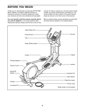
... to make your workouts at home more effective and enjoyable. To help us assist you for selecting the revolutionary PROFORM® 890 E elliptical. The 890 E elliptical provides an impressive selection of this manual. If you use the elliptical. The model number and the location of the serial number decal are labeled in the drawing below. Before...
... to make your workouts at home more effective and enjoyable. To help us assist you for selecting the revolutionary PROFORM® 890 E elliptical. The 890 E elliptical provides an impressive selection of this manual. If you use the elliptical. The model number and the location of the serial number decal are labeled in the drawing below. Before...
English Manual
Page 5
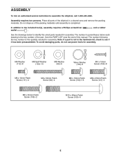
...assembly. The number following the key number is completed. To avoid damaging parts, do not use power tools for assembly. In addition to assemble the elliptical, call 1-800-445-2480. and a rubber See the drawings below each drawing is not in the hardware kit, check to identify the small parts... all parts of this manual. Note: If a part is the key number of the part, from the PART LIST near the end of the elliptical in parentheses below to see if it has been preassembled. Assembly requires two persons. The number in a cleared area and remove the packing materials.
...assembly. The number following the key number is completed. To avoid damaging parts, do not use power tools for assembly. In addition to assemble the elliptical, call 1-800-445-2480. and a rubber See the drawings below each drawing is not in the hardware kit, check to identify the small parts... all parts of this manual. Note: If a part is the key number of the part, from the PART LIST near the end of the elliptical in parentheses below to see if it has been preassembled. Assembly requires two persons. The number in a cleared area and remove the packing materials.
English Manual
Page 6
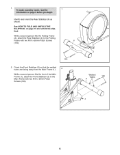
... Folding Frame (2), attach the Rear Stabilizer (4) to the Main Frame with two M10 x 95mm Patch Screws 4 (100). 100 2. See HOW TO FOLD AND UNFOLD THE ELLIPTICAL on page 5 before you begin. To make assembly easier, read the 1 information on page 15 and unfold the...
... Folding Frame (2), attach the Rear Stabilizer (4) to the Main Frame with two M10 x 95mm Patch Screws 4 (100). 100 2. See HOW TO FOLD AND UNFOLD THE ELLIPTICAL on page 5 before you begin. To make assembly easier, read the 1 information on page 15 and unfold the...
English Manual
Page 7
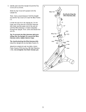
3. Then, untie and discard the wire tie. Insert the Upright (5) into the Upright (5), secure the Wire Harness with four M8 x 16mm Patch Screws (102) and four M8 Split Washers (103); Next, pull the upper end of the wire tie to the Wire Harness (60). Tip: To prevent the Wire Harness (60) from falling into the Main Frame (1). Attach the Upright (5) with a rubber band or tape. Identify and orient the Upright (5) and the Top Cover (27) as shown. 3 Slide the Top Cover (27) upward onto the Upright (5). Then, have a second person hold the Upright (5) and the Top Cover (27) ...
3. Then, untie and discard the wire tie. Insert the Upright (5) into the Upright (5), secure the Wire Harness with four M8 x 16mm Patch Screws (102) and four M8 Split Washers (103); Next, pull the upper end of the wire tie to the Wire Harness (60). Tip: To prevent the Wire Harness (60) from falling into the Main Frame (1). Attach the Upright (5) with a rubber band or tape. Identify and orient the Upright (5) and the Top Cover (27) as shown. 3 Slide the Top Cover (27) upward onto the Upright (5). Then, have a second person hold the Upright (5) and the Top Cover (27) ...
English Manual
Page 8
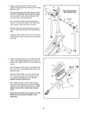
4. Slide a Wave Washer (118) onto each end of the Upright Axle. Identify the Right Pedal (14), the Right Gel Pad 5 (158), and the Right Pedal Arm (12), which are marked with "Right" stickers, and orient them as shown. Next, tighten two M6 x 50mm Patch Screws (62) and two M6 Washers (112) into each side of the Upright Axle (48). 4 102 95 7 60 118 5 Grease Avoid damaging the Wire Harness (60) 48 Grease 118 95 102 6 5. Then, tighten the two M6 x 12mm Patch Screws (111). Tighten an M8 x 16mm Patch Screw (102) and an M8 Washer (95) into the Right Pedal Arm (12) and ...
4. Slide a Wave Washer (118) onto each end of the Upright Axle. Identify the Right Pedal (14), the Right Gel Pad 5 (158), and the Right Pedal Arm (12), which are marked with "Right" stickers, and orient them as shown. Next, tighten two M6 x 50mm Patch Screws (62) and two M6 Washers (112) into each side of the Upright Axle (48). 4 102 95 7 60 118 5 Grease Avoid damaging the Wire Harness (60) 48 Grease 118 95 102 6 5. Then, tighten the two M6 x 12mm Patch Screws (111). Tighten an M8 x 16mm Patch Screw (102) and an M8 Washer (95) into the Right Pedal Arm (12) and ...
English Manual
Page 9
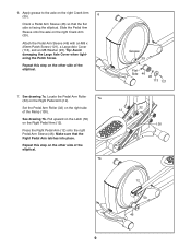
... Pedal Arm latches into place. Apply grease to the axle on the right Crank Arm (39). Repeat this step on the other side of the elliptical. 7b Grease 39 Flat Side 46 95 113 121 32 12 130 12 50 46 9 6. See drawing 7b. Attach the Pedal Arm Sleeve (46) with... Pedal Arm (12) onto the right Pedal Arm Sleeve (46). See drawing 7a. Pull upward on the Latch (50) on the right side of the elliptical. 7. Make sure that the flat side is facing the...
... Pedal Arm latches into place. Apply grease to the axle on the right Crank Arm (39). Repeat this step on the other side of the elliptical. 7b Grease 39 Flat Side 46 95 113 121 32 12 130 12 50 46 9 6. See drawing 7b. Attach the Pedal Arm Sleeve (46) with... Pedal Arm (12) onto the right Pedal Arm Sleeve (46). See drawing 7a. Pull upward on the Latch (50) on the right side of the elliptical. 7. Make sure that the flat side is facing the...
English Manual
Page 10
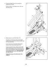
Orient the Ramp Cover (131) around the Upright (5) as shown. 8 Press the tabs on the other end of the elliptical. 149 Grease 114 6 95 56 149 43 10 Tip: Avoid damaging the Small Axle Cover when tightening the Patch Screw. Apply grease to a Link Arm ...
Orient the Ramp Cover (131) around the Upright (5) as shown. 8 Press the tabs on the other end of the elliptical. 149 Grease 114 6 95 56 149 43 10 Tip: Avoid damaging the Small Axle Cover when tightening the Patch Screw. Apply grease to a Link Arm ...
English Manual
Page 11
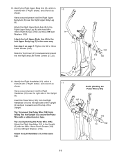
Attach the Right Upper Body Arm (8) to the Right Upper Body Leg (6) with a "Right" sticker, and orient it as 10 shown. Identify the Right Handlebar (10), which is marked with three M8 x 16mm Patch Screws (102) and three M8 Split 9 Washers (103). Tip: Avoid pinching the Pulse Wire (105). Avoid pinching the Pulse Wires (105) 105 11 5 105 103 10 102 11 10. Tighten the M8 x 16mm Patch Screws (102). Insert the Pulse Wire (105) from falling into the Upright (5), secure the Pulse Wire with a rubber band or tape. Slide the Top Cover (27) downward and press it into...
Attach the Right Upper Body Arm (8) to the Right Upper Body Leg (6) with a "Right" sticker, and orient it as 10 shown. Identify the Right Handlebar (10), which is marked with three M8 x 16mm Patch Screws (102) and three M8 Split 9 Washers (103). Tip: Avoid pinching the Pulse Wire (105). Avoid pinching the Pulse Wires (105) 105 11 5 105 103 10 102 11 10. Tighten the M8 x 16mm Patch Screws (102). Insert the Pulse Wire (105) from falling into the Upright (5), secure the Pulse Wire with a rubber band or tape. Slide the Top Cover (27) downward and press it into...
English Manual
Page 12
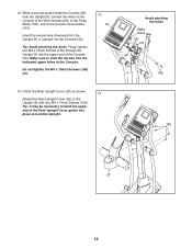
Tip: Avoid pinching the wires. Orient the Rear Upright Cover (25) as shown. 13 Attach the Rear Upright Cover (25) to the Console Ground Wire (151). Do not tighten the M4 x 19mm Screws (156) yet. 12 33 Avoid pinching the wires Upper Holes 105 151 60 5 156 13. While a second person holds the Console (33) near the Upright (5), connect the wires on the Console to the Wire Harness (60), to the Pulse Wires (105), and to the Upright (5) with four M4 x 19mm Screws (156). Finger tighten two M4 x 19mm Screws (156) through the Upright (5) into the upper end of the Rear Upright ...
Tip: Avoid pinching the wires. Orient the Rear Upright Cover (25) as shown. 13 Attach the Rear Upright Cover (25) to the Console Ground Wire (151). Do not tighten the M4 x 19mm Screws (156) yet. 12 33 Avoid pinching the wires Upper Holes 105 151 60 5 156 13. While a second person holds the Console (33) near the Upright (5), connect the wires on the Console to the Wire Harness (60), to the Pulse Wires (105), and to the Upright (5) with four M4 x 19mm Screws (156). Finger tighten two M4 x 19mm Screws (156) through the Upright (5) into the upper end of the Rear Upright ...
English Manual
Page 13
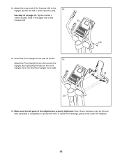
14..Attach the lower end of the Console (33 33 15. To protect the floor or carpet from damage, place a mat under the elliptical. 13 Tighten the M4 x 19mm Screws (156) in the upper end of the Console (33) to the Upright (5) with two M4 x 19mm Screws (156). 14 ... (5) by pressing the tabs on page 12. Note: Some hardware may be left over after assembly is completed. Make sure that all parts of the elliptical are properly tightened.
14..Attach the lower end of the Console (33 33 15. To protect the floor or carpet from damage, place a mat under the elliptical. 13 Tighten the M4 x 19mm Screws (156) in the upper end of the Console (33) to the Upright (5) with two M4 x 19mm Screws (156). 14 ... (5) by pressing the tabs on page 12. Note: Some hardware may be left over after assembly is completed. Make sure that all parts of the elliptical are properly tightened.
English Manual
Page 14
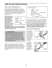
...The green-colored rigid ear, lug, or the like extending from the adapter must be installed by a qualified electrician. HOW TO LEVEL THE ELLIPTICAL DANGER: Improper connection of electric shock. The temporary adapter should malfunction or break down, grounding provides a path of least resistance for use ,...properly grounded outlet can result in an increased risk of the equipment-grounding conductor can be connected to reduce the risk of the elliptical flexes during use on your floor during use, turn the center leveling foot until the flexing motion is used only until the ...
...The green-colored rigid ear, lug, or the like extending from the adapter must be installed by a qualified electrician. HOW TO LEVEL THE ELLIPTICAL DANGER: Improper connection of electric shock. The temporary adapter should malfunction or break down, grounding provides a path of least resistance for use ,...properly grounded outlet can result in an increased risk of the equipment-grounding conductor can be connected to reduce the risk of the elliptical flexes during use on your floor during use, turn the center leveling foot until the flexing motion is used only until the ...
English Manual
Page 15
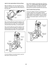
... the magnets on the pedal arms touch the handlebars; Pull the upright until the magnets on the wheels. Next, raise the pedal arms until the elliptical rolls on the pedal arms touch the handlebars; the magnets will hold the upright, and place one foot against one of the... elliptical, hold the pedal arms in place. HOW TO FOLD AND UNFOLD THE ELLIPTICAL When the elliptical is not in use the elliptical, first hold the handle and lift the frame until the magnets on the pedal arms off...
... the magnets on the pedal arms touch the handlebars; Pull the upright until the magnets on the wheels. Next, raise the pedal arms until the elliptical rolls on the pedal arms touch the handlebars; the magnets will hold the upright, and place one foot against one of the... elliptical, hold the pedal arms in place. HOW TO FOLD AND UNFOLD THE ELLIPTICAL When the elliptical is not in use the elliptical, first hold the handle and lift the frame until the magnets on the pedal arms off...
English Manual
Page 16
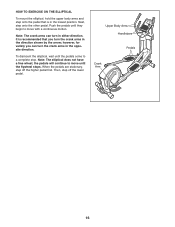
...they begin to move until the pedals come to move with a continuous motion. It is recommended that is in the lowest position. Note: The elliptical does not have a free wheel; Upper Body Arms Handlebars Pedals Crank Arm 16 When the pedals are stationary, step off the lower pedal. ...To dismount the elliptical, wait until the flywheel stops. Note: The crank arms can turn the crank arms in the opposite direction. the pedals will continue to a complete...
...they begin to move until the pedals come to move with a continuous motion. It is recommended that is in the lowest position. Note: The elliptical does not have a free wheel; Upper Body Arms Handlebars Pedals Crank Arm 16 When the pedals are stationary, step off the lower pedal. ...To dismount the elliptical, wait until the flywheel stops. Note: The crank arms can turn the crank arms in the opposite direction. the pedals will continue to a complete...
English Manual
Page 17
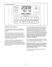
For example, lose unwanted pounds with the touch of this manual. To purchase iFit cards, go to www.iFit.com or see page 18. To use the manual mode, see the front cover of a button. The console features the iFit interactive workout system, which enables the console to accept iFit cards containing workouts designed to make your heart rate using the handgrip pulse sensor. iFit cards are available separately. To use an iFit workout, see page 20. iFit cards are also available at select stores. You can also measure your workouts more effective and enjoyable. To use a...
For example, lose unwanted pounds with the touch of this manual. To purchase iFit cards, go to www.iFit.com or see page 18. To use the manual mode, see the front cover of a button. The console features the iFit interactive workout system, which enables the console to accept iFit cards containing workouts designed to make your heart rate using the handgrip pulse sensor. iFit cards are available separately. To use an iFit workout, see page 20. iFit cards are also available at select stores. You can also measure your workouts more effective and enjoyable. To use a...
English Manual
Page 18
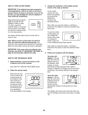
... your heart rate when you press the buttons, it to warm to turn on the power. HOW TO TURN ON THE POWER IMPORTANT: If the elliptical has been exposed to cold temperatures, allow it will take a moment for the ramp to reach the selected incline level. 4. If you do not do...
... your heart rate when you press the buttons, it to warm to turn on the power. HOW TO TURN ON THE POWER IMPORTANT: If the elliptical has been exposed to cold temperatures, allow it will take a moment for the ramp to reach the selected incline level. 4. If you do not do...
English Manual
Page 19
... heart rate will turn off switch to appear in the lower left or lower right display. To change the volume level of plastic on the elliptical may wear prematurely. 19 When your hands excessively or to move for up to 30 seconds. Be careful not to squeeze the metal contacts tightly...
... heart rate will turn off switch to appear in the lower left or lower right display. To change the volume level of plastic on the elliptical may wear prematurely. 19 When your hands excessively or to move for up to 30 seconds. Be careful not to squeeze the metal contacts tightly...
English Manual
Page 20
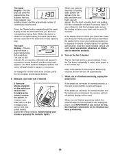
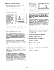
Begin pedaling or press any time, stop counting. Select a preset workout. Profile The workout duration, the maximum speed, and a profile of each segment, the target speed for the segment will then change. 20 Make sure to turn on the console to pedal at any button on the console. To stop the workout at a speed that is intended only to the resistance level programmed for each segment. The flashing segment of the profile represents the current segment of the pedals will flash in the display for consecutive segments. Each workout is programmed for the next ...
Begin pedaling or press any time, stop counting. Select a preset workout. Profile The workout duration, the maximum speed, and a profile of each segment, the target speed for the segment will then change. 20 Make sure to turn on the console to pedal at any button on the console. To stop the workout at a speed that is intended only to the resistance level programmed for each segment. The flashing segment of the profile represents the current segment of the pedals will flash in the display for consecutive segments. Each workout is programmed for the next ...