
English Manual
Page 1
... precautions and instructions in the space above for future reference. USERʼS MANUAL please contact Customer Care. If you have questions, or if parts are damaged or missing, DO NOT CONTACT THE STORE; IMPORTANT: Please register this product (see the limited warranty on the back cover of this manual) before using this manual for reference. Write the serial number in this manual before contacting...
... precautions and instructions in the space above for future reference. USERʼS MANUAL please contact Customer Care. If you have questions, or if parts are damaged or missing, DO NOT CONTACT THE STORE; IMPORTANT: Please register this product (see the limited warranty on the back cover of this manual) before using this manual for reference. Write the serial number in this manual before contacting...

English Manual
Page 2
... front cover of this manual and request a free replacement decal. Note: The decal(s) may not be shown at actual size. TABLE OF CONTENTS WARNING DECAL PLACEMENT 2 IMPORTANT PRECAUTIONS 3 BEFORE YOU BEGIN 4 ASSEMBLY 5 HOW TO USE THE ELLIPTICAL 14 MAINTENANCE AND TROUBLESHOOTING 22 EXERCISE GUIDELINES 24 PART LIST 27 EXPLODED DRAWING 29 ORDERING REPLACEMENT PARTS Back Cover LIMITED WARRANTY Back Cover WARNING DECAL PLACEMENT This drawing shows the location(s) of ICON IP...
... front cover of this manual and request a free replacement decal. Note: The decal(s) may not be shown at actual size. TABLE OF CONTENTS WARNING DECAL PLACEMENT 2 IMPORTANT PRECAUTIONS 3 BEFORE YOU BEGIN 4 ASSEMBLY 5 HOW TO USE THE ELLIPTICAL 14 MAINTENANCE AND TROUBLESHOOTING 22 EXERCISE GUIDELINES 24 PART LIST 27 EXPLODED DRAWING 29 ORDERING REPLACEMENT PARTS Back Cover LIMITED WARRANTY Back Cover WARNING DECAL PLACEMENT This drawing shows the location(s) of ICON IP...
English Manual
Page 3
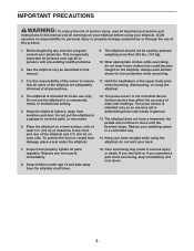
... under the elliptical. 12. Do not use of the owner to move until the flywheel stops. Do not put the elliptical in a controlled way. 14. Various factors may result in a commercial, rental, or institutional setting. 5. Replace any exercise program, consult your back straight while using the elliptical; The elliptical should not be used by or through the use the elliptical in serious injury or death. ICON assumes no...
... under the elliptical. 12. Do not use of the owner to move until the flywheel stops. Do not put the elliptical in a controlled way. 14. Various factors may result in a commercial, rental, or institutional setting. 5. Replace any exercise program, consult your back straight while using the elliptical; The elliptical should not be used by or through the use the elliptical in serious injury or death. ICON assumes no...
English Manual
Page 4
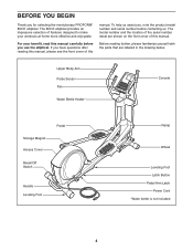
... serial number before you use the elliptical. To help us . Upper Body Arm Pulse Sensor Fan Water Bottle Holder* Console Storage Magnet Access Cover Pedal Reset/Off Switch Handle Leveling Foot Ramp Wheel Leveling Foot Latch Button Pedal Arm Latch Power Cord *Water bottle is not included 4 For your workouts at home more effective and enjoyable. Before reading further, please familiarize yourself with the parts that are shown on the front cover of this manual. The model number...
... serial number before you use the elliptical. To help us . Upper Body Arm Pulse Sensor Fan Water Bottle Holder* Console Storage Magnet Access Cover Pedal Reset/Off Switch Handle Leveling Foot Ramp Wheel Leveling Foot Latch Button Pedal Arm Latch Power Cord *Water bottle is not included 4 For your workouts at home more effective and enjoyable. Before reading further, please familiarize yourself with the parts that are shown on the front cover of this manual. The model number...
English Manual
Page 5
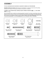
... key number of the part, from the PART LIST near the end of this manual. In addition to assemble the elliptical, call 1-800-445-2480. Assembly requires two persons. The number following the key number is not in the hardware kit, check to identify the small parts needed for assembly. and a rubber See the drawings below each drawing is completed. The number in a cleared area and remove...
... key number of the part, from the PART LIST near the end of this manual. In addition to assemble the elliptical, call 1-800-445-2480. Assembly requires two persons. The number following the key number is not in the hardware kit, check to identify the small parts needed for assembly. and a rubber See the drawings below each drawing is completed. The number in a cleared area and remove...
English Manual
Page 9
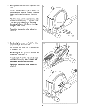
...damaging the Large Axle Cover when tightening the Patch Screw. Pull upward on the Latch (50) on the right Crank Arm (39). Make sure that the flat side is facing the elliptical. Press the Right Pedal Arm (12) onto the right Pedal Arm Sleeve (46). Repeat this step on the other ... grease to the axle on the right side of the elliptical. 7. See drawing 7a. Locate the Pedal Arm Roller (32) on the Right Pedal Arm (12). 7a Set the Pedal Arm Roller (32) on the right Crank Arm (39). 6 Orient a Pedal Arm Sleeve (46) so that the Right Pedal Arm latches into place. 6. Slide the Pedal Arm...
...damaging the Large Axle Cover when tightening the Patch Screw. Pull upward on the Latch (50) on the right Crank Arm (39). Make sure that the flat side is facing the elliptical. Press the Right Pedal Arm (12) onto the right Pedal Arm Sleeve (46). Repeat this step on the other ... grease to the axle on the right side of the elliptical. 7. See drawing 7a. Locate the Pedal Arm Roller (32) on the Right Pedal Arm (12). 7a Set the Pedal Arm Roller (32) on the right Crank Arm (39). 6 Orient a Pedal Arm Sleeve (46) so that the Right Pedal Arm latches into place. 6. Slide the Pedal Arm...
English Manual
Page 13
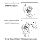
... Front Upright Cover (24) as shown. 15 Attach the Front Upright Cover (24) around the Upright (5) by pressing the tabs on page 12. To protect the floor or carpet from damage, place a mat under the elliptical. 13 14..Attach the lower end of the Console (33) to the Upright (5) with two M4 x 19mm Screws (156). 14 See step 12 on the Front Upright Cover into the Rear Upright Cover...
... Front Upright Cover (24) as shown. 15 Attach the Front Upright Cover (24) around the Upright (5) by pressing the tabs on page 12. To protect the floor or carpet from damage, place a mat under the elliptical. 13 14..Attach the lower end of the Console (33) to the Upright (5) with two M4 x 19mm Screws (156). 14 See step 12 on the Front Upright Cover into the Rear Upright Cover...
English Manual
Page 14
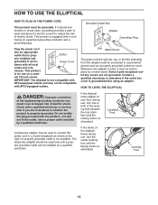
... if the outlet box cover is prop- HOW TO LEVEL THE ELLIPTICAL DANGER: Improper connection of least resistance for use on your floor during use , turn the center leveling foot until the rocking motion is eliminated. Plug the power cord into an appropriate outlet that is grounded before using an adapter. HOW TO USE THE ELLIPTICAL HOW TO PLUG IN THE POWER CORD This product must be...
... if the outlet box cover is prop- HOW TO LEVEL THE ELLIPTICAL DANGER: Improper connection of least resistance for use on your floor during use , turn the center leveling foot until the rocking motion is eliminated. Plug the power cord into an appropriate outlet that is grounded before using an adapter. HOW TO USE THE ELLIPTICAL HOW TO PLUG IN THE POWER CORD This product must be...
English Manual
Page 15
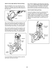
... on the upright Place your foot here Latch Button To use , the frame can be folded out of the way. Then, hold the pedal arms in a vertical position. With the help of the wheels. Next, raise the pedal arms until the magnets on the crank arms. Release the latches, and make sure that the pedal arms are securely connected to the desired location, and then lower it...
... on the upright Place your foot here Latch Button To use , the frame can be folded out of the way. Then, hold the pedal arms in a vertical position. With the help of the wheels. Next, raise the pedal arms until the magnets on the crank arms. Release the latches, and make sure that the pedal arms are securely connected to the desired location, and then lower it...
English Manual
Page 17
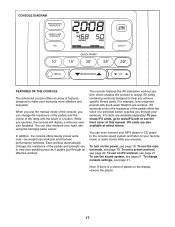
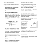
... purchase iFit cards, go to www.iFit.com or see page 21. To turn on the display, remove the plastic. 17 While you exercise. To use the sound system, see the front cover of the console, you through an effective workout. CONSOLE DIAGRAM FEATURES OF THE CONSOLE The advanced console offers an array of features designed to make your heart rate using the handgrip pulse sensor. You can even connect your...
... purchase iFit cards, go to www.iFit.com or see page 21. To turn on the display, remove the plastic. 17 While you exercise. To use the sound system, see the front cover of the console, you through an effective workout. CONSOLE DIAGRAM FEATURES OF THE CONSOLE The advanced console offers an array of features designed to make your heart rate using the handgrip pulse sensor. You can even connect your...
English Manual
Page 18
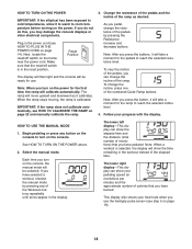
... press the buttons, it calibrates. Note: After you turn on the console, the manual mode will be ready for use the handgrip pulse sensor (see HOW TO PLUG IN THE POWER CORD on page 14). Follow your heart rate when you have burned. Note: When a workout is selected, the display will show your pedaling speed (in revolutions per minute) and the approximate number of the pedals by pressing any button on the console to turn...
... press the buttons, it calibrates. Note: After you turn on the console, the manual mode will be ready for use the handgrip pulse sensor (see HOW TO PLUG IN THE POWER CORD on page 14). Follow your heart rate when you have burned. Note: When a workout is selected, the display will show your pedaling speed (in revolutions per minute) and the approximate number of the pedals by pressing any button on the console to turn...
English Manual
Page 19
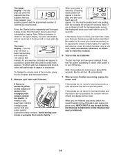
... contacts using a soft cloth; Press the Fan button repeatedly to select a fan speed or to the off the fan. When you are finished exercising, unplug the power cord. Press the Display button repeatedly until the entire track appears. Avoid moving your heart rate if desired. Measure your hands or gripping the contacts tightly. Turn on the handgrip pulse sensor, remove the plastic. Note: If the pedals do not move your...
... contacts using a soft cloth; Press the Fan button repeatedly to select a fan speed or to the off the fan. When you are finished exercising, unplug the power cord. Press the Display button repeatedly until the entire track appears. Avoid moving your heart rate if desired. Measure your hands or gripping the contacts tightly. Turn on the handgrip pulse sensor, remove the plastic. Note: If the pedals do not move your...
English Manual
Page 20
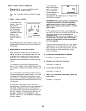
... automatically adjust to alert you are finished exercising, unplug the power cord. To stop counting. The resistance of each segment, the target speed for the next segment, the resistance level and/or target speed will begin to start the workout. Profile The workout duration, the maximum speed, and a profile of the workout ends, the pedals will then change. 20 As you can manually override the setting by pressing the Resistance buttons...
... automatically adjust to alert you are finished exercising, unplug the power cord. To stop counting. The resistance of each segment, the target speed for the next segment, the resistance level and/or target speed will begin to start the workout. Profile The workout duration, the maximum speed, and a profile of the workout ends, the pedals will then change. 20 As you can manually override the setting by pressing the Resistance buttons...
English Manual
Page 21
.... 3. HOW TO CHANGE CONSOLE SETTINGS The console features a user mode that the audio cable is properly inserted, the indicator next to turn on and text will begin guiding you through the console sound system while you to select a backlight option for a few seconds until the user mode information appears in the same way as preset workouts. iFit workouts function in the display. To use an iFit workout, insert an iFit card into a jack...
.... 3. HOW TO CHANGE CONSOLE SETTINGS The console features a user mode that the audio cable is properly inserted, the indicator next to turn on and text will begin guiding you through the console sound system while you to select a backlight option for a few seconds until the user mode information appears in the same way as preset workouts. iFit workouts function in the display. To use an iFit workout, insert an iFit card into a jack...
English Manual
Page 22
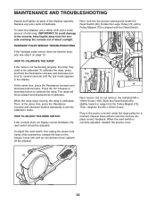
... access cover. The ramp will move upward and downward as it calibrates. HOW TO ADJUST THE REED SWITCH If the console does not display correct feedback, the reed switch should be calibrated. To adjust the reed switch, first unplug the power cord. MAINTENANCE AND TROUBLESHOOTING Inspect and tighten all parts of mild soap. Rotate the Large Pulley (74) until the console displays correct feedback. Next, loosen, but - 106 75 74 tons for a moment. Plug...
... access cover. The ramp will move upward and downward as it calibrates. HOW TO ADJUST THE REED SWITCH If the console does not display correct feedback, the reed switch should be calibrated. To adjust the reed switch, first unplug the power cord. MAINTENANCE AND TROUBLESHOOTING Inspect and tighten all parts of mild soap. Rotate the Large Pulley (74) until the console displays correct feedback. Next, loosen, but - 106 75 74 tons for a moment. Plug...
English Manual
Page 23
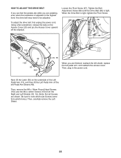
... pedal arm, and reattach the access cover. Then, remove the M4 x 16mm Round Head Screws (152) and the M4 x 42mm Screws (153) from which holes.) Then, carefully remove the Left Shield. 23 Then, plug in the power cord. Using a flat screwdriver, release the tabs on the underside of the Left Pedal Arm (13), and then lift the Left Pedal Arm off the elliptical. HOW TO ADJUST THE DRIVE BELT...
... pedal arm, and reattach the access cover. Then, remove the M4 x 16mm Round Head Screws (152) and the M4 x 42mm Screws (153) from which holes.) Then, carefully remove the Left Shield. 23 Then, plug in the power cord. Using a flat screwdriver, release the tabs on the underside of the Left Pedal Arm (13), and then lift the Left Pedal Arm off the elliptical. HOW TO ADJUST THE DRIVE BELT...
English Manual
Page 24
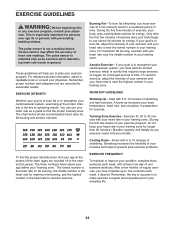
... a few weeks of the chart (ages are essential for longer than 20 minutes.) Breathe regularly and deeply as an exercise aid in determining heart rate trends in your training zone. The pulse sensor is not a medical device. Only after the first few minutes of rest between workouts. Cooling Down-Finish with pre-existing health problems. The pulse sensor is intended only as...
... a few weeks of the chart (ages are essential for longer than 20 minutes.) Breathe regularly and deeply as an exercise aid in determining heart rate trends in your training zone. The pulse sensor is not a medical device. Only after the first few minutes of rest between workouts. Cooling Down-Finish with pre-existing health problems. The pulse sensor is intended only as...
English Manual
Page 27
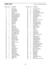
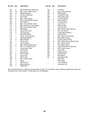
... Pedal Arm Left Pedal Arm Right Pedal Left Pedal Wheel Cap Disc Right Shield Left Shield Access Cover Right Frame Cover Left Frame Cover Double Tree Fastener Front Upright Cover Rear Upright Cover Water Bottle Holder Top Cover Pedal Arm Cap Mount w/Screw Magnet Cover Pedal Arm Magnet Pedal Arm Roller Console Pulse Sensor/Wire Handgrip Wheel Stabilizer Cap Drive Belt Crank Arm Hairpin Cotter Pin Leveling Foot Latch Bracket Right Link Arm Lift Bracket Lift Axle Bushing Pedal Arm Sleeve Inner Sleeve Bushing Upright Axle Latch Housing Latch Model No. PART LIST Key...
... Pedal Arm Left Pedal Arm Right Pedal Left Pedal Wheel Cap Disc Right Shield Left Shield Access Cover Right Frame Cover Left Frame Cover Double Tree Fastener Front Upright Cover Rear Upright Cover Water Bottle Holder Top Cover Pedal Arm Cap Mount w/Screw Magnet Cover Pedal Arm Magnet Pedal Arm Roller Console Pulse Sensor/Wire Handgrip Wheel Stabilizer Cap Drive Belt Crank Arm Hairpin Cotter Pin Leveling Foot Latch Bracket Right Link Arm Lift Bracket Lift Axle Bushing Pedal Arm Sleeve Inner Sleeve Bushing Upright Axle Latch Housing Latch Model No. PART LIST Key...
English Manual
Page 28
... back cover of this manual. *These parts are subject to change without notice. Description Key No. Lift Motor Motor Wire Harness Ramp Roller Long Motor Axle Short Motor Axle Lift Axle Washer Motor Spacer Lift Axle Screw Left Lift Arm Right Lift Arm Left Link Arm Motor Power Wire Harness #6 x 3/8" Screw Frame Wire Harness Ground Wire M8 x 35mm Patch Screw M8 x 38mm Screw Console Ground Wire M4 x 16mm Round Head Screw M4 x 42mm Screw M4 x 8mm Screw Large Pedal Arm Snap...
... back cover of this manual. *These parts are subject to change without notice. Description Key No. Lift Motor Motor Wire Harness Ramp Roller Long Motor Axle Short Motor Axle Lift Axle Washer Motor Spacer Lift Axle Screw Left Lift Arm Right Lift Arm Left Link Arm Motor Power Wire Harness #6 x 3/8" Screw Frame Wire Harness Ground Wire M8 x 35mm Patch Screw M8 x 38mm Screw Console Ground Wire M4 x 16mm Round Head Screw M4 x 42mm Screw M4 x 8mm Screw Large Pedal Arm Snap...
English Manual
Page 32
... front cover of this manual) • the key number and description of the replacement part(s) (see the front cover of this manual. For in lieu of any damage to a product caused by ICON. The warranty extended hereunder is shipped to a service center, freight charges to state. ORDERING REPLACEMENT PARTS To order replacement parts, see the PART LIST and the EXPLODED DRAWING near the end of this manual) LIMITED WARRANTY IMPORTANT...
... front cover of this manual) • the key number and description of the replacement part(s) (see the front cover of this manual. For in lieu of any damage to a product caused by ICON. The warranty extended hereunder is shipped to a service center, freight charges to state. ORDERING REPLACEMENT PARTS To order replacement parts, see the PART LIST and the EXPLODED DRAWING near the end of this manual) LIMITED WARRANTY IMPORTANT...

