

User Manual
Page 2
... 2 TABLE OF CONTENTS WARNING DECAL PLACEMENT 2 IMPORTANT PRECAUTIONS 3 BEFORE YOU BEGIN 4 ASSEMBLY 5 HOW TO USE THE ELLIPTICAL 15 MAINTENANCE AND TROUBLESHOOTING 21 EXERCISE GUIDELINES 23 PART LIST 25 EXPLODED DRAWING 26 ORDERING ...REPLACEMENT PARTS Back Cover LIMITED WARRANTY Back Cover WARNING DECAL PLACEMENT This drawing shows the location(s) of this manual and request a free replacement decal. Note: The decal(s) may not be shown at actual size. PROFORM...
... 2 TABLE OF CONTENTS WARNING DECAL PLACEMENT 2 IMPORTANT PRECAUTIONS 3 BEFORE YOU BEGIN 4 ASSEMBLY 5 HOW TO USE THE ELLIPTICAL 15 MAINTENANCE AND TROUBLESHOOTING 21 EXERCISE GUIDELINES 23 PART LIST 25 EXPLODED DRAWING 26 ORDERING ...REPLACEMENT PARTS Back Cover LIMITED WARRANTY Back Cover WARNING DECAL PLACEMENT This drawing shows the location(s) of this manual and request a free replacement decal. Note: The decal(s) may not be shown at actual size. PROFORM...
User Manual
Page 5
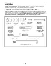
...of this manual. The number in parentheses below to identify the small parts needed for assembly. Note: If a part is not in a cleared area and remove the packing materials. ASSEMBLY Assembly requires two persons. In addition to see if it has been preassembled. The number following...(82)-4 Shoulder Patch Bolt (31)-2 5 Place all parts of the elliptical in the hardware kit, check to the included tool(s), assembly requires a Phillips screwdriver . To avoid damaging parts, do not use power tools for assembly. See the drawings below each drawing is the key number of the ...
...of this manual. The number in parentheses below to identify the small parts needed for assembly. Note: If a part is not in a cleared area and remove the packing materials. ASSEMBLY Assembly requires two persons. In addition to see if it has been preassembled. The number following...(82)-4 Shoulder Patch Bolt (31)-2 5 Place all parts of the elliptical in the hardware kit, check to the included tool(s), assembly requires a Phillips screwdriver . To avoid damaging parts, do not use power tools for assembly. See the drawings below each drawing is the key number of the ...

User Manual
Page 6
While a second person lifts the rear of the Frame (1), attach the Rear Stabilizer (70) to the Frame with two M10 x 85mm Patch Screws (82). 70 82 2. Orient the Front Stabilizer (73) so that the "Front" sticker is facing away from the front of the Frame (1), attach the Front Stabilizer (73) to the Frame with two M10 x 85mm Patch Screws (82). 1 73 82 1 6 While a second person lifts the front of 2 the Frame (1). To make assembly easier, read the infor- 1 mation on page 5 before you begin. 1.
While a second person lifts the rear of the Frame (1), attach the Rear Stabilizer (70) to the Frame with two M10 x 85mm Patch Screws (82). 70 82 2. Orient the Front Stabilizer (73) so that the "Front" sticker is facing away from the front of the Frame (1), attach the Front Stabilizer (73) to the Frame with two M10 x 85mm Patch Screws (82). 1 73 82 1 6 While a second person lifts the front of 2 the Frame (1). To make assembly easier, read the infor- 1 mation on page 5 before you begin. 1.

User Manual
Page 8
... left side of the Handlebar (39). See the upper drawing. See the lower drawing. 5. To avoid pinching or damaging the Pulse Wires (28) while you 5 assemble the Handlebar (39), perform the fol- Attach the Handlebar (39) to the Upright (2) with three M10 x 20mm Patch Screws (79). 2 39 28 28 79 79...
... left side of the Handlebar (39). See the upper drawing. See the lower drawing. 5. To avoid pinching or damaging the Pulse Wires (28) while you 5 assemble the Handlebar (39), perform the fol- Attach the Handlebar (39) to the Upright (2) with three M10 x 20mm Patch Screws (79). 2 39 28 28 79 79...

User Manual
Page 14
Press the Rear Shield Cover (59) onto the Left and Right Shields (44, 45). 16 59 44 45 17. To protect the floor or carpet from damage, place a mat under the elliptical. 14 Note: Some hardware may be left over after assembly is completed. 16. Make sure that all parts of the elliptical are properly tightened.
Press the Rear Shield Cover (59) onto the Left and Right Shields (44, 45). 16 59 44 45 17. To protect the floor or carpet from damage, place a mat under the elliptical. 14 Note: Some hardware may be left over after assembly is completed. 16. Make sure that all parts of the elliptical are properly tightened.
User Manual
Page 16
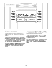
... 9). You can even connect your MP3 player or CD player to the console sound system and listen to make sure that batteries are installed (see assembly step 6 on the display, remove the plastic. 16 You can change the resistance of the pedals with the touch of the pedals as it guides...
... 9). You can even connect your MP3 player or CD player to the console sound system and listen to make sure that batteries are installed (see assembly step 6 on the display, remove the plastic. 16 You can change the resistance of the pedals with the touch of the pedals as it guides...

User Manual
Page 21
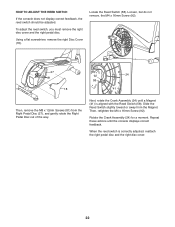
..., the rear shield cover, the top shield cover, and the left shield. Replace any worn parts immediately. 44 To clean the elliptical, use a damp cloth and a small amount of the elliptical regularly. HOW TO ADJUST THE DRIVE BELT If you can feel the pedals slip while you must remove the left pedal..., the batteries should be adjusted. 92 92 Next, loosen the Pivot Screw (88). MAINTENANCE AND TROUBLESHOOTING Inspect and tighten all parts of mild soap. See assembly step 6 on page 18. Slide the top shield cover upward. 88 Remove the M4 x 16mm Screws (92) from the left pedal. 21
..., the rear shield cover, the top shield cover, and the left shield. Replace any worn parts immediately. 44 To clean the elliptical, use a damp cloth and a small amount of the elliptical regularly. HOW TO ADJUST THE DRIVE BELT If you can feel the pedals slip while you must remove the left pedal..., the batteries should be adjusted. 92 92 Next, loosen the Pivot Screw (88). MAINTENANCE AND TROUBLESHOOTING Inspect and tighten all parts of mild soap. See assembly step 6 on page 18. Slide the top shield cover upward. 88 Remove the M4 x 16mm Screws (92) from the left pedal. 21
User Manual
Page 22
... reed switch should be adjusted. Using a flat screwdriver, remove the right Disc Cover (18). Then, retighten the M4 x 16mm Screw (92). Next, rotate the Crank Assembly (24) until the console displays correct feedback. When the reed switch is aligned with the Reed Switch (58). Repeat these actions until a Magnet (41) is...
... reed switch should be adjusted. Using a flat screwdriver, remove the right Disc Cover (18). Then, retighten the M4 x 16mm Screw (92). Next, rotate the Crank Assembly (24) until the console displays correct feedback. When the reed switch is aligned with the Reed Switch (58). Repeat these actions until a Magnet (41) is...

User Manual
Page 25
PFCCEL53909.0 R0411A Key No. Qty. Description Key No. Assembly Tool * - PART LIST Model No. Grease Packet * - For information about ordering replacement parts, see the back cover of this manual. *These parts are subject to ...
PFCCEL53909.0 R0411A Key No. Qty. Description Key No. Assembly Tool * - PART LIST Model No. Grease Packet * - For information about ordering replacement parts, see the back cover of this manual. *These parts are subject to ...


