User Guide
Page 2
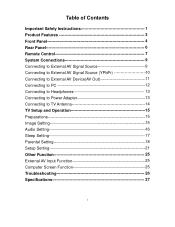
... Signal Source (YPbPr 10 Connecting to External AV Device(AV Out 11 Connecting to PC 12 Connecting to Headphones 13 Connecting to Power Adapter 13 Connecting to TV Antenna 14 TV Setup and Operation 15 Preparations 15 Image Setting 15 Audio Setting 16 Sleep Setting 17 Parental Setting 18 Setup Setting 21 Other...
... Signal Source (YPbPr 10 Connecting to External AV Device(AV Out 11 Connecting to PC 12 Connecting to Headphones 13 Connecting to Power Adapter 13 Connecting to TV Antenna 14 TV Setup and Operation 15 Preparations 15 Image Setting 15 Audio Setting 16 Sleep Setting 17 Parental Setting 18 Setup Setting 21 Other...
User Guide
Page 3
... potential adverse effects on the environment and human health. Refer to do so. POWER SUPPLY: Plug the two-prong end of the power cord to www.polaroid.com and click on the product means it . NOTE: Before plugging the power cord into an AC outlet, make sure that this product is intended to alert...
... potential adverse effects on the environment and human health. Refer to do so. POWER SUPPLY: Plug the two-prong end of the power cord to www.polaroid.com and click on the product means it . NOTE: Before plugging the power cord into an AC outlet, make sure that this product is intended to alert...
User Guide
Page 4
...registers, stoves, or other limited viewing uses only unless otherwise authorized by Macrovision, and is used, use near any ventilation openings. Protect the power cord from being walked on or pinched particularly at plugs, convenience receptacles, and the point where they exit from tip-over. 13. Refer...to dripping or splashing and no objects filled with one wider than the other intellectual property rights. Note: Do not touch the color TFT LCD screen by the manufacturer. 12. Heed all instructions. 5. If the provided plug does not fit into the apparatus, the apparatus has ...
...registers, stoves, or other limited viewing uses only unless otherwise authorized by Macrovision, and is used, use near any ventilation openings. Protect the power cord from being walked on or pinched particularly at plugs, convenience receptacles, and the point where they exit from tip-over. 13. Refer...to dripping or splashing and no objects filled with one wider than the other intellectual property rights. Note: Do not touch the color TFT LCD screen by the manufacturer. 12. Heed all instructions. 5. If the provided plug does not fit into the apparatus, the apparatus has ...
User Guide
Page 7
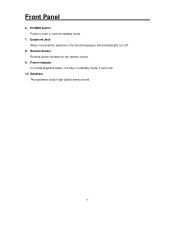
Remote Sensor Remote sensor window for the remote control. 9. POWER button Press to earphone, the internal speakers will automatically turn off. 8. in standby mode, it is blue; Front Panel 6. Power Indicator In normal playback status, it turns red. 10. Earphone Jack When connected to enter or exit the standby mode. 7. Speakers Two speakers output high quality stereo sound. - 6 -
Remote Sensor Remote sensor window for the remote control. 9. POWER button Press to earphone, the internal speakers will automatically turn off. 8. in standby mode, it is blue; Front Panel 6. Power Indicator In normal playback status, it turns red. 10. Earphone Jack When connected to enter or exit the standby mode. 7. Speakers Two speakers output high quality stereo sound. - 6 -
User Guide
Page 8
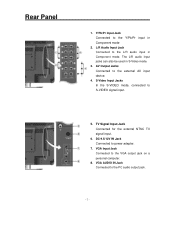
...mode, connected to the Y/Pb/Pr input in Component mode 2. Y/Pb/Pr Input Jack Connected to S-VIDEO signal input. 5. TV Signal Input Jack Connected for the external NTSC TV signal input. 6. The L/R audio input jacks can also be used in Component mode. DC 9.5/12V IN Jack Connected to the... VGA output jack on a personal computer. 8. VGA Input Jack Connected to power adapter. 7. L/R Audio Input Jack Connected to the L/R audio ...
...mode, connected to the Y/Pb/Pr input in Component mode 2. Y/Pb/Pr Input Jack Connected to S-VIDEO signal input. 5. TV Signal Input Jack Connected for the external NTSC TV signal input. 6. The L/R audio input jacks can also be used in Component mode. DC 9.5/12V IN Jack Connected to the... VGA output jack on a personal computer. 8. VGA Input Jack Connected to power adapter. 7. L/R Audio Input Jack Connected to the L/R audio ...
User Guide
Page 9
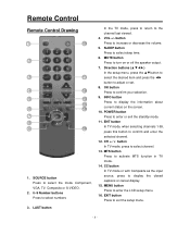
... or exit the standby mode. 11. POWER button Press to confirm your selection. 9. MTS button Press to the channel last viewed. 4. LAST button In the TV mode, press to return to activate MTS function in TV mode. 14. MUTE button Press to enter the LCD setup menu. 16. VOL +/- MENU ...button Press to turn on the screen. 10. SOURCE button Press to select the mode Component, VGA, TV, Composite or S-VIDEO. 2. 0~9 Number buttons Press to display ...
... or exit the standby mode. 11. POWER button Press to confirm your selection. 9. MTS button Press to the channel last viewed. 4. LAST button In the TV mode, press to return to activate MTS function in TV mode. 14. MUTE button Press to enter the LCD setup menu. 16. VOL +/- MENU ...button Press to turn on the screen. 10. SOURCE button Press to select the mode Component, VGA, TV, Composite or S-VIDEO. 2. 0~9 Number buttons Press to display ...
User Guide
Page 11
... on the rear panel of the unit to the external AV signal source. Use the S-VIDEO cable to connect the S-VIDEO input jack on the power of the unit and the external AV signal source and press the SOURCE button to shift to the external AV signal source. Note: the L/R audio... input jacks can be used in the both Composite and S-VIDEO modes. - 10 - System Connections • Do not connect the power cord until all AV connections, turn on the rear panel of the unit to Composite or S-VIDEO mode. After making all other connections have been...
... on the rear panel of the unit to the external AV signal source. Use the S-VIDEO cable to connect the S-VIDEO input jack on the power of the unit and the external AV signal source and press the SOURCE button to shift to the external AV signal source. Note: the L/R audio... input jacks can be used in the both Composite and S-VIDEO modes. - 10 - System Connections • Do not connect the power cord until all AV connections, turn on the rear panel of the unit to Composite or S-VIDEO mode. After making all other connections have been...
User Guide
Page 12
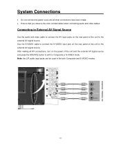
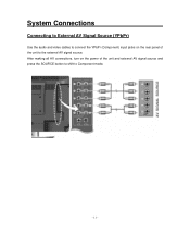
System Connections Connecting to External AV Signal Source (YPbPr) Use the audio and video cables to connect the YPbPr (Component) input jacks on the power of the unit to Component mode. - 11 - After making all AV connections, turn on the rear panel of the unit and external AV signal source and press the SOURCE button to shift to the external AV signal source.
System Connections Connecting to External AV Signal Source (YPbPr) Use the audio and video cables to connect the YPbPr (Component) input jacks on the power of the unit to Component mode. - 11 - After making all AV connections, turn on the rear panel of the unit and external AV signal source and press the SOURCE button to shift to the external AV signal source.
User Guide
Page 15
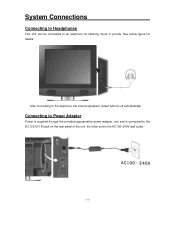
Connecting to Power Adapter Power is supplied through the provided appropriative power adapter, one end is connected to the DC 9.5/12V IN jack on the rear panel of the unit, the other end to an earphone for details: After connecting to the earphone, the internal speakers' output will turn off automatically. System Connections Connecting to Headphones This unit can be connected to the AC100~240V wall outlet. - 14 - See below figure for listening music in private.
Connecting to Power Adapter Power is supplied through the provided appropriative power adapter, one end is connected to the DC 9.5/12V IN jack on the rear panel of the unit, the other end to an earphone for details: After connecting to the earphone, the internal speakers' output will turn off automatically. System Connections Connecting to Headphones This unit can be connected to the AC100~240V wall outlet. - 14 - See below figure for listening music in private.
User Guide
Page 16
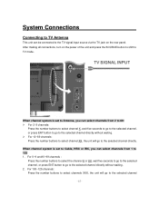
... will go to the selected channel - 15 - System Connections Connecting to TV Antenna This unit can be connected to the TV signal input source via the TV jack on the power of the unit and press the SOURCE button to shift to TV mode. When channel system is set to Cable, HRC or IRC, you...
... will go to the selected channel - 15 - System Connections Connecting to TV Antenna This unit can be connected to the TV signal input source via the TV jack on the power of the unit and press the SOURCE button to shift to TV mode. When channel system is set to Cable, HRC or IRC, you...

User Guide
Page 17
... SOURCE button to shift to adjust the value. Brightness Setup Press the ▲▼ button to select Brightness and press the ◄► button to TV mode. directly . * X is signal input. You can go on the right: In the setup menu, press the ▲▼ button to select Image...the ▲▼ button to confirm your selection. Press the MENU button to return to turn on the power. (If it is turned on, the power indicator is blue.) 2. After making all connections, press the POWER button to the previous menu. - 16 - Scheme Setup Press the ▲▼ button to select ...
... SOURCE button to shift to adjust the value. Brightness Setup Press the ▲▼ button to select Brightness and press the ◄► button to TV mode. directly . * X is signal input. You can go on the right: In the setup menu, press the ▲▼ button to select Image...the ▲▼ button to confirm your selection. Press the MENU button to return to turn on the power. (If it is turned on, the power indicator is blue.) 2. After making all connections, press the POWER button to the previous menu. - 16 - Scheme Setup Press the ▲▼ button to select ...
User Guide
Page 27
...is turned on and the connections are inserted and the polarity is correct. Other Notes: Static or other external interference may cause the LCD TV to reset the player. Make sure the power adapter is no obstructions between the remote control and the player. The remote control does not work. In the... TV mode, set the items in correct video type. There is correctly connected. Make sure battery is turned on the LCD. Make sure the unit is...
...is turned on and the connections are inserted and the polarity is correct. Other Notes: Static or other external interference may cause the LCD TV to reset the player. Make sure the power adapter is no obstructions between the remote control and the player. The remote control does not work. In the... TV mode, set the items in correct video type. There is correctly connected. Make sure battery is turned on the LCD. Make sure the unit is...
User Guide
Page 28
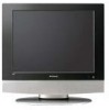
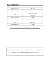
Specifications TFT-LCD Resolution TFT-LCD Screen Size Power Power Consumption Dimension Weight Ambient Temperature 800 x 600 20 inches AC100~240V 50/60Hz DC 12V 5A < 60W 490mm ×478mm ×184mm (LXWXD) About 9.52 Kg 10~45 DESIGN AND SPECIFICATIONS ARE SUBJECT TO CHANGE WITHOUT NOTICE "Polaroid" and "Polaroid and Pixel" are trademarks of Polaroid Corporation, Waltham, MA, USA. For service, support and warranty information, visit www.polaroid.com. - 27 -
Specifications TFT-LCD Resolution TFT-LCD Screen Size Power Power Consumption Dimension Weight Ambient Temperature 800 x 600 20 inches AC100~240V 50/60Hz DC 12V 5A < 60W 490mm ×478mm ×184mm (LXWXD) About 9.52 Kg 10~45 DESIGN AND SPECIFICATIONS ARE SUBJECT TO CHANGE WITHOUT NOTICE "Polaroid" and "Polaroid and Pixel" are trademarks of Polaroid Corporation, Waltham, MA, USA. For service, support and warranty information, visit www.polaroid.com. - 27 -


