Service Manual
Page 1
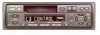
... C PIONEER ELECTRONIC CORPORATION 1998 K-ZZB. This service manual does not describe the CD test mode. EXPLODED VIEWS AND PARTS LIST 2 3. PCB CONNECTION DIAGRAM 18 5. See the separate manual CX-644(CRT1800) for the cassette mechanism description. - ADJUSTMENT 32 7. SAFETY INFORMATION 2 2. Service KEH-P2800/X1M/UC Manual ORDER NO. CRT2268 MULTI-CD CONTROL HIGH POWER CASSETTE PLAYER WITH...
... C PIONEER ELECTRONIC CORPORATION 1998 K-ZZB. This service manual does not describe the CD test mode. EXPLODED VIEWS AND PARTS LIST 2 3. PCB CONNECTION DIAGRAM 18 5. See the separate manual CX-644(CRT1800) for the cassette mechanism description. - ADJUSTMENT 32 7. SAFETY INFORMATION 2 2. Service KEH-P2800/X1M/UC Manual ORDER NO. CRT2268 MULTI-CD CONTROL HIGH POWER CASSETTE PLAYER WITH...
Service Manual
Page 8
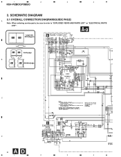
A-a Large size A-a A-b SCH diagram B FM/AM TUNER UNIT CWE1467(/UC) CWE1486(/ES) A-a A-b Guide page B A-a A-b Detailed page 220 C D CASSETTE 24dBs PCB D 8 AD 1 2 3 4 1 2 3 4 KEH-P2800,P3850 3. SCHEMATIC DIAGRAM 3.1 OVERALL CONNECTION DIAGRAM(GUIDE PAGE) A Note: When ordering service parts, be sure to refer to "EXPLODED VIEWS AND PARTS LIST" or "ELECTRICAL PARTS LIST".
A-a Large size A-a A-b SCH diagram B FM/AM TUNER UNIT CWE1467(/UC) CWE1486(/ES) A-a A-b Guide page B A-a A-b Detailed page 220 C D CASSETTE 24dBs PCB D 8 AD 1 2 3 4 1 2 3 4 KEH-P2800,P3850 3. SCHEMATIC DIAGRAM 3.1 OVERALL CONNECTION DIAGRAM(GUIDE PAGE) A Note: When ordering service parts, be sure to refer to "EXPLODED VIEWS AND PARTS LIST" or "ELECTRICAL PARTS LIST".
Service Manual
Page 18
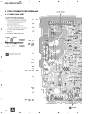
Viewpoint of PCB diagrams Connector Capacitor SIDE A B P.C.Board Chip Part SIDE B A TUNER AMP UNIT 3 4 CORD ASSY C D A 18 C CN901 1 2 3 4 For further information for several destination. PCB CONNECTION DIAGRAM A 4.1 TUNER AMP UNIT NOTE FOR PCB DIAGRAMS 1. 1 2 KEH-P2800,P3850 4. The parts mounted on this PCB include all necessary parts for respective destinations, be sure to check with the schematic diagram. 2.
Viewpoint of PCB diagrams Connector Capacitor SIDE A B P.C.Board Chip Part SIDE B A TUNER AMP UNIT 3 4 CORD ASSY C D A 18 C CN901 1 2 3 4 For further information for several destination. PCB CONNECTION DIAGRAM A 4.1 TUNER AMP UNIT NOTE FOR PCB DIAGRAMS 1. 1 2 KEH-P2800,P3850 4. The parts mounted on this PCB include all necessary parts for respective destinations, be sure to check with the schematic diagram. 2.
Service Manual
Page 32
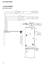
KEH-P2800,P3850 6. ADJUSTMENT - Connection Diagram TUNER AMP UNIT BACK UP ACC GND Lch + Lch - 4Ω Rch + Rch - 4Ω +14.4V DC Regulated GND P o w e r S u p p l y mV Meter (1) Oscilloscope Antenna Dummy Antenna 50Ω(37.5Ω) FM SSG 50Ω(75Ω) Stereo Modulator FM/AM TUNER UNIT (TOP VIEW) L2 Pin26 Antenna L4 T31 Pin 19 DC V Pin14 Meter(1) L5 Pin13 FM/AM TUNER UNIT VR154 T51 Pin1 FM/AM TUNER UNIT (BOTTOM VIEW) T51 Center Meter C63 32
KEH-P2800,P3850 6. ADJUSTMENT - Connection Diagram TUNER AMP UNIT BACK UP ACC GND Lch + Lch - 4Ω Rch + Rch - 4Ω +14.4V DC Regulated GND P o w e r S u p p l y mV Meter (1) Oscilloscope Antenna Dummy Antenna 50Ω(37.5Ω) FM SSG 50Ω(75Ω) Stereo Modulator FM/AM TUNER UNIT (TOP VIEW) L2 Pin26 Antenna L4 T31 Pin 19 DC V Pin14 Meter(1) L5 Pin13 FM/AM TUNER UNIT VR154 T51 Pin1 FM/AM TUNER UNIT (BOTTOM VIEW) T51 Center Meter C63 32
Service Manual
Page 41
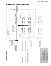
...another unit, refer to the 2 speakers in the front or the rear. To terminal always supplied with RCA pin plugs (sold separately) KEH-P2800,P3850 CAUTION • Cords for this for other units may be different colors even if they have the same function. Red Yellow With ... ≠ 41 Use this unit and those for connections when you have the same function. OPERATIONS AND SPECIFICATIONS Connection Diagram This Unit Rear output Antenna jack Multi-CD player (sold separately) Connecting cords with power regardless of the power amp or Autoantenna relay control terminal. (Max. 300 ...
...another unit, refer to the 2 speakers in the front or the rear. To terminal always supplied with RCA pin plugs (sold separately) KEH-P2800,P3850 CAUTION • Cords for this for other units may be different colors even if they have the same function. Red Yellow With ... ≠ 41 Use this unit and those for connections when you have the same function. OPERATIONS AND SPECIFICATIONS Connection Diagram This Unit Rear output Antenna jack Multi-CD player (sold separately) Connecting cords with power regardless of the power amp or Autoantenna relay control terminal. (Max. 300 ...


