Service Manual
Page 1
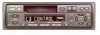
... For the operations in the CD test mode, refer to the CD player's Service Manual. This service manual does not describe the CD test mode. Haven 1087 Keetberglaan 1, 9120 Melsele, Belgium PIONEER ELECTRONICS ASIACENTRE PTE.LTD. 253 Alexandra Road, #04-01, Singapore 159936 C PIONEER ELECTRONIC CORPORATION 1998 K-ZZB. ELECTRICAL PARTS LIST 26 6. CRT2268 MULTI-CD CONTROL HIGH POWER CASSETTE PLAYER WITH FM/AM TUNER KEH-P2800 KEH-P3850 X1M...
... For the operations in the CD test mode, refer to the CD player's Service Manual. This service manual does not describe the CD test mode. Haven 1087 Keetberglaan 1, 9120 Melsele, Belgium PIONEER ELECTRONICS ASIACENTRE PTE.LTD. 253 Alexandra Road, #04-01, Singapore 159936 C PIONEER ELECTRONIC CORPORATION 1998 K-ZZB. ELECTRICAL PARTS LIST 26 6. CRT2268 MULTI-CD CONTROL HIGH POWER CASSETTE PLAYER WITH FM/AM TUNER KEH-P2800 KEH-P3850 X1M...
Service Manual
Page 2
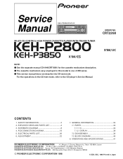
... of this manual. Health & Safety Code Section 25249.6 - Qualified technicians have the necessary test equipment and tools, and have been trained to a qualified service technician. you are known to the state of California to perform the repair of the ... and refer the repair to properly and safely repair complex products such as those covered by this product properly and safely; KEH-P2800,P3850 1. SAFETY INFORMATION CAUTION This service manual is not meant for qualified service technicians; Proposition 65 2. it -yourselfer. EXPLODED VIEWS AND PARTS LIST 2.1 PACKING ...
... of this manual. Health & Safety Code Section 25249.6 - Qualified technicians have the necessary test equipment and tools, and have been trained to a qualified service technician. you are known to the state of California to perform the repair of the ... and refer the repair to properly and safely repair complex products such as those covered by this product properly and safely; KEH-P2800,P3850 1. SAFETY INFORMATION CAUTION This service manual is not meant for qualified service technicians; Proposition 65 2. it -yourselfer. EXPLODED VIEWS AND PARTS LIST 2.1 PACKING ...
Service Manual
Page 3
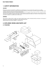
... 14 Protector 15 Protector CEG1173 CHG3598 CHL3598 CHP1622 CHP1623 CEG-162 CHG3599 CHL3599 CHP1622 CHP1623 16 Owner's Manual 17 Owner's Manual 18 Installation Manual * 19 Card 20 Case Assy CRD2804 Not used CRD2805 ARY1048 CXB3520 CRD2801 CRD2802 CRD2803 Not used for disassembly. - Parts marked by "*" are generally unavailable because they are used CXB3520 - PACKING SECTION PARTS LIST Mark No. KEH-P2800,P3850 NOTE: -
... 14 Protector 15 Protector CEG1173 CHG3598 CHL3598 CHP1622 CHP1623 CEG-162 CHG3599 CHL3599 CHP1622 CHP1623 16 Owner's Manual 17 Owner's Manual 18 Installation Manual * 19 Card 20 Case Assy CRD2804 Not used CRD2805 ARY1048 CXB3520 CRD2801 CRD2802 CRD2803 Not used for disassembly. - Parts marked by "*" are generally unavailable because they are used CXB3520 - PACKING SECTION PARTS LIST Mark No. KEH-P2800,P3850 NOTE: -
Service Manual
Page 5
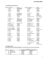
... Lighting Conductor CNV5752 68 Case Assy CXB3520 69 Transistor(Q804) 2SD2396 70 Cassette Mechanism Assy EXK3450 71 Fuse(FU951)(10A) 72 IC(IC501) * 73 Cord CEK1136 TDA7384 See Contrast table(2) (2) CONTRAST TABLE KEH-P2800/X1M/UC and KEH-P3850/X1M/ES are constructed the same except for the following: Mark No. 12 16 45 58 * 73 Description Tuner Amp Unit...
... Lighting Conductor CNV5752 68 Case Assy CXB3520 69 Transistor(Q804) 2SD2396 70 Cassette Mechanism Assy EXK3450 71 Fuse(FU951)(10A) 72 IC(IC501) * 73 Cord CEK1136 TDA7384 See Contrast table(2) (2) CONTRAST TABLE KEH-P2800/X1M/UC and KEH-P3850/X1M/ES are constructed the same except for the following: Mark No. 12 16 45 58 * 73 Description Tuner Amp Unit...
Service Manual
Page 7
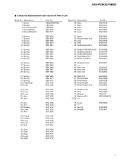
... Unit 53 Arm * 54 PCB 55 Switch(Eject)(S4) ENV1487 EXA1516 ENV1519 ENP1161 ESG1006 11 Spring 12 Spring 13 Spring 14 Spring 15 Spring EBH1559 EBH1593 EBH1561 EBH1562 EBH1563 56 Switch(FWD)(REV)(S3) 57 Switch(Load)(S1) 58 Switch(Mute)(S2) 59 Head Assy(HD1) 60 Motor Unit(M1... ENV1470 ENV1517 ENV1472 ENV1510 7 Description 46 Gear 47 Gear 48 Gear 49 Gear 50 Lever Part No. BSZ23P050FMC CBG1003 CKS2829 EBA1038 EBA1037 Mark No. Description 1 Screw 2 Washer 3 Connector(CN1) 4 Screw(M2x5) 5 Screw(M2x2.5) Part No. CASSETTE MECHANISM ASSY SECTION PARTS LIST Mark No. KEH-P2800,P3850 -
... Unit 53 Arm * 54 PCB 55 Switch(Eject)(S4) ENV1487 EXA1516 ENV1519 ENP1161 ESG1006 11 Spring 12 Spring 13 Spring 14 Spring 15 Spring EBH1559 EBH1593 EBH1561 EBH1562 EBH1563 56 Switch(FWD)(REV)(S3) 57 Switch(Load)(S1) 58 Switch(Mute)(S2) 59 Head Assy(HD1) 60 Motor Unit(M1... ENV1470 ENV1517 ENV1472 ENV1510 7 Description 46 Gear 47 Gear 48 Gear 49 Gear 50 Lever Part No. BSZ23P050FMC CBG1003 CKS2829 EBA1038 EBA1037 Mark No. Description 1 Screw 2 Washer 3 Connector(CN1) 4 Screw(M2x5) 5 Screw(M2x2.5) Part No. CASSETTE MECHANISM ASSY SECTION PARTS LIST Mark No. KEH-P2800,P3850 -
Service Manual
Page 8
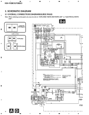
1 2 3 4 KEH-P2800,P3850 3. SCHEMATIC DIAGRAM 3.1 OVERALL CONNECTION DIAGRAM(GUIDE PAGE) A Note: When ordering service parts, be sure to refer to "EXPLODED VIEWS AND PARTS LIST" or "ELECTRICAL PARTS LIST". A-a Large size A-a A-b SCH diagram B FM/AM TUNER UNIT CWE1467(/UC) CWE1486(/ES) A-a A-b Guide page B A-a A-b Detailed page 220 C D CASSETTE 24dBs PCB D 8 AD 1 2 3 4
1 2 3 4 KEH-P2800,P3850 3. SCHEMATIC DIAGRAM 3.1 OVERALL CONNECTION DIAGRAM(GUIDE PAGE) A Note: When ordering service parts, be sure to refer to "EXPLODED VIEWS AND PARTS LIST" or "ELECTRICAL PARTS LIST". A-a Large size A-a A-b SCH diagram B FM/AM TUNER UNIT CWE1467(/UC) CWE1486(/ES) A-a A-b Guide page B A-a A-b Detailed page 220 C D CASSETTE 24dBs PCB D 8 AD 1 2 3 4
Service Manual
Page 18
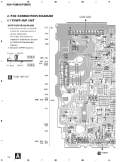
For further information for several destination. The parts mounted on this PCB include all necessary parts for respective destinations, be sure to check with the schematic diagram. 2. Viewpoint of PCB diagrams Connector Capacitor SIDE A B P.C.Board Chip Part SIDE B A TUNER AMP UNIT 3 4 CORD ASSY C D A 18 C CN901 1 2 3 4 1 2 KEH-P2800,P3850 4. PCB CONNECTION DIAGRAM A 4.1 TUNER AMP UNIT NOTE FOR PCB DIAGRAMS 1.
For further information for several destination. The parts mounted on this PCB include all necessary parts for respective destinations, be sure to check with the schematic diagram. 2. Viewpoint of PCB diagrams Connector Capacitor SIDE A B P.C.Board Chip Part SIDE B A TUNER AMP UNIT 3 4 CORD ASSY C D A 18 C CN901 1 2 3 4 1 2 KEH-P2800,P3850 4. PCB CONNECTION DIAGRAM A 4.1 TUNER AMP UNIT NOTE FOR PCB DIAGRAMS 1.
Service Manual
Page 25
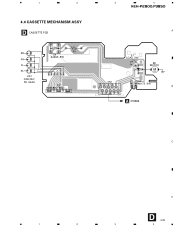
1 2 4.4 CASSETTE MECHANISM ASSY D CASSETTE PCB RR FR FL RL HD1 FWD/REV PB HEAD R1 S4 EJECT SW S3 FWD/REV SW 3 4 KEH-P2800,P3850 A S1 LOAD SW D1 M1 MOTOR M CN1 13 579 S2 MUTE SW B 2 4 6 8 10 A CN604 C D D 25 1 2 3 4
1 2 4.4 CASSETTE MECHANISM ASSY D CASSETTE PCB RR FR FL RL HD1 FWD/REV PB HEAD R1 S4 EJECT SW S3 FWD/REV SW 3 4 KEH-P2800,P3850 A S1 LOAD SW D1 M1 MOTOR M CN1 13 579 S2 MUTE SW B 2 4 6 8 10 A CN604 C D D 25 1 2 3 4
Service Manual
Page 32
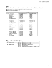
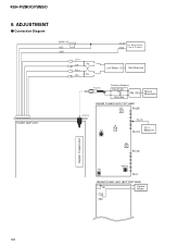
Connection Diagram TUNER AMP UNIT BACK UP ACC GND Lch + Lch - 4Ω Rch + Rch - 4Ω +14.4V DC Regulated GND P o w e r S u p p l y mV Meter (1) Oscilloscope Antenna Dummy Antenna 50Ω(37.5Ω) FM SSG 50Ω(75Ω) Stereo Modulator FM/AM TUNER UNIT (TOP VIEW) L2 Pin26 Antenna L4 T31 Pin 19 DC V Pin14 Meter(1) L5 Pin13 FM/AM TUNER UNIT VR154 T51 Pin1 FM/AM TUNER UNIT (BOTTOM VIEW) T51 Center Meter C63 32 ADJUSTMENT - KEH-P2800,P3850 6.
Connection Diagram TUNER AMP UNIT BACK UP ACC GND Lch + Lch - 4Ω Rch + Rch - 4Ω +14.4V DC Regulated GND P o w e r S u p p l y mV Meter (1) Oscilloscope Antenna Dummy Antenna 50Ω(37.5Ω) FM SSG 50Ω(75Ω) Stereo Modulator FM/AM TUNER UNIT (TOP VIEW) L2 Pin26 Antenna L4 T31 Pin 19 DC V Pin14 Meter(1) L5 Pin13 FM/AM TUNER UNIT VR154 T51 Pin1 FM/AM TUNER UNIT (BOTTOM VIEW) T51 Center Meter C63 32 ADJUSTMENT - KEH-P2800,P3850 6.
Service Manual
Page 33
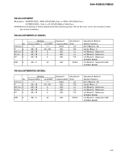
... Frequency(MHz) Level(dBf) 98.1 M 60-100 98.1 M 5 98.1 M 5 98.1 M 5 Displayed Frequency(MHz) 107.9 98.1 98.1 98.1 98.1 Adjustment Point L5 T51 L2 L4 T31 ARC 6 98.1 S 40 98.1 VR154 Adjustment Method (Switch Position) DC V Meter(1) : 6V Center Meter : 0 mV Meter(1) : Maximum mV Meter(1) : Maximum mV Meter(1) : Maximum (STEREO MODE) mV Meter(1) : Separation 5dB (STEREO MODE) FM ADJUSTMENT(ES MODEL) No. KEH-P2800,P3850 FM ADJUSTMENT...
... Frequency(MHz) Level(dBf) 98.1 M 60-100 98.1 M 5 98.1 M 5 98.1 M 5 Displayed Frequency(MHz) 107.9 98.1 98.1 98.1 98.1 Adjustment Point L5 T51 L2 L4 T31 ARC 6 98.1 S 40 98.1 VR154 Adjustment Method (Switch Position) DC V Meter(1) : 6V Center Meter : 0 mV Meter(1) : Maximum mV Meter(1) : Maximum mV Meter(1) : Maximum (STEREO MODE) mV Meter(1) : Separation 5dB (STEREO MODE) FM ADJUSTMENT(ES MODEL) No. KEH-P2800,P3850 FM ADJUSTMENT...
Service Manual
Page 34
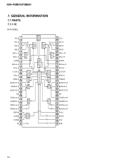
...PARTS 7.1.1 IC SN761029DL AVcc IN1-L IN2-L IN3-L IN4(+)-L IN4(-)-L AGND SWout-L ZCin-L LOUD-L VRin-L TREB-L BASS-C1-L BASS-R-L BASS-C2-L NC TONEout-L FADERin-L FRNTout-L REARout-L VREFin AGND DGND Ct 3 Line Serial Bus Zero-cross A Detector Gain Adjust Gain Adjust Power Supply Fader Volume, Treble Bass Loudness Isolator VCC IN1-R IN2-R IN3-R IN4(+)-R IN4(-)-R AGND SWout-R ZCin-R LOUD-R VRin-R TREB-R BASS-C1-R BASS-R-R BASS... 29 28 27 26 25 1 2 3 4 5 6 7 8 9 10 11 12 13 14 15 16 17 18 19 20 21 22 23 24 Isolator Supply A Power Fader Volume, Loudness Treble Bass KEH-P2800,P3850 7.
...PARTS 7.1.1 IC SN761029DL AVcc IN1-L IN2-L IN3-L IN4(+)-L IN4(-)-L AGND SWout-L ZCin-L LOUD-L VRin-L TREB-L BASS-C1-L BASS-R-L BASS-C2-L NC TONEout-L FADERin-L FRNTout-L REARout-L VREFin AGND DGND Ct 3 Line Serial Bus Zero-cross A Detector Gain Adjust Gain Adjust Power Supply Fader Volume, Treble Bass Loudness Isolator VCC IN1-R IN2-R IN3-R IN4(+)-R IN4(-)-R AGND SWout-R ZCin-R LOUD-R VRin-R TREB-R BASS-C1-R BASS-R-R BASS... 29 28 27 26 25 1 2 3 4 5 6 7 8 9 10 11 12 13 14 15 16 17 18 19 20 21 22 23 24 Isolator Supply A Power Fader Volume, Loudness Treble Bass KEH-P2800,P3850 7.
Service Manual
Page 35
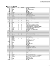
... mute output Mechanism mute cancel output Not used GND Not used FM power control output AM power control output Slave power supply control output Not used Eject key input Tape loading input Cassette mechanism power output Mechanism mute input Normal reverse input Not used Reset input IP BUS data input Not used Clock input ACC power sense input Back up power sense input SD input FM stereo input Power supply Oscillator output Oscillator input GND Not used Test program mode input A/D converter analog power supply (VDD) (A/D converter standard voltage input) Signal level input Model select input...
... mute output Mechanism mute cancel output Not used GND Not used FM power control output AM power control output Slave power supply control output Not used Eject key input Tape loading input Cassette mechanism power output Mechanism mute input Normal reverse input Not used Reset input IP BUS data input Not used Clock input ACC power sense input Back up power sense input SD input FM stereo input Power supply Oscillator output Oscillator input GND Not used Test program mode input A/D converter analog power supply (VDD) (A/D converter standard voltage input) Signal level input Model select input...
Service Manual
Page 36
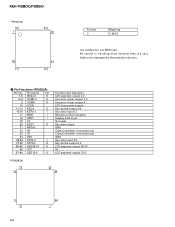
... 57-64 SEG12-5 O Function and Operation LCD segment output 4-0 Common driver output 1-3 Common driver output 0 LCD bias power supply Key strobe output 3-0 Key data input 0,1 Remote control reception Display data input Not used Key data output GND Crystal oscillator connection pin Crystal oscillator connection pin GND Key data input 2,3 Key strobe output 5,4 LCD segment output 39-13 5V LCD segment output 12-5 *PD6293A 48 33 32 49 17 64 16 1 36 KEH-P2800,P3850 *PE5015A 80...
... 57-64 SEG12-5 O Function and Operation LCD segment output 4-0 Common driver output 1-3 Common driver output 0 LCD bias power supply Key strobe output 3-0 Key data input 0,1 Remote control reception Display data input Not used Key data output GND Crystal oscillator connection pin Crystal oscillator connection pin GND Key data input 2,3 Key strobe output 5,4 LCD segment output 39-13 5V LCD segment output 12-5 *PD6293A 48 33 32 49 17 64 16 1 36 KEH-P2800,P3850 *PE5015A 80...
Service Manual
Page 39
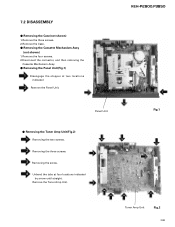
Remove the three screws. 2. Remove the Tuner Amp Unit. 7.2 DISASSEMBLY - Remove the Case. - Panel Unit - Remove the four screws. 2.Disconnect the connector, and then removing the Cassette Mechanism Assy. - KEH-P2800,P3850 Fig.1 Tuner Amp Unit Fig.2 39 Removing the three screws. Removing the screw. Removing the Cassette Mechanism Assy (not shown) 1. Removing the Panel Unit(Fig.1) Disengage the stopper at four locations indicated by arrow until straight. Unbend the tabs at two locations indicated Remove the Panel Unit. Removing the...
Remove the three screws. 2. Remove the Tuner Amp Unit. 7.2 DISASSEMBLY - Remove the Case. - Panel Unit - Remove the four screws. 2.Disconnect the connector, and then removing the Cassette Mechanism Assy. - KEH-P2800,P3850 Fig.1 Tuner Amp Unit Fig.2 39 Removing the three screws. Removing the screw. Removing the Cassette Mechanism Assy (not shown) 1. Removing the Panel Unit(Fig.1) Disengage the stopper at four locations indicated by arrow until straight. Unbend the tabs at two locations indicated Remove the Panel Unit. Removing the...
Service Manual
Page 41
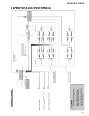
... Violet Violet/black Right speaker + Front ≠ + Rear ≠ Power amp (sold separately) Connecting cords with power regardless of both units and connect cords that have the same function. When connecting this unit to another unit, refer to the 2 speakers in the front or the rear. OPERATIONS AND SPECIFICATIONS Connection Diagram This Unit Rear output Antenna jack Multi-CD player (sold separately) KEH-P2800,P3850 CAUTION • Cords for this for other units may be different colors even if they...
... Violet Violet/black Right speaker + Front ≠ + Rear ≠ Power amp (sold separately) Connecting cords with power regardless of both units and connect cords that have the same function. When connecting this unit to another unit, refer to the 2 speakers in the front or the rear. OPERATIONS AND SPECIFICATIONS Connection Diagram This Unit Rear output Antenna jack Multi-CD player (sold separately) KEH-P2800,P3850 CAUTION • Cords for this for other units may be different colors even if they...
Service Manual
Page 42
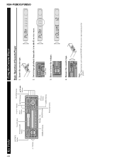
buttons Buttons 1-6 DISPLAY button BAND button Detach button AUDIO button Function button 2. Switch tape playback from side A to side B, or vice versa. Remove the cassette tape. Same Time 3. Note: • The Tape function can be turned ON/OFF with the cassette tape remaining in this product. KEH-P2800,P3850 42 Key Finder SOURCE button Cassette door Programmable button !/⁄ buttons CLOCK button Eject button LOUD button 5/∞/2/3 buttons Using the Cassette Player Basic Operation of Cassette Player 1. Raise or lower the volume. 4. Insert the cassette tape. +/-...
buttons Buttons 1-6 DISPLAY button BAND button Detach button AUDIO button Function button 2. Switch tape playback from side A to side B, or vice versa. Remove the cassette tape. Same Time 3. Note: • The Tape function can be turned ON/OFF with the cassette tape remaining in this product. KEH-P2800,P3850 42 Key Finder SOURCE button Cassette door Programmable button !/⁄ buttons CLOCK button Eject button LOUD button 5/∞/2/3 buttons Using the Cassette Player Basic Operation of Cassette Player 1. Raise or lower the volume. 4. Insert the cassette tape. +/-...
Service Manual
Page 43
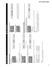
... the volume. 5. Each press of the Function button selects the mode in with the Seek Tuning function, tune in the following order: BSM = LOCAL Note: • You can select tuner functions. • Select the desired mode in Function Menu. KEH-P2800,P3850 43 Tuner Operation Basic Operation of the time you press the button. Frequency appears on the display. ("STEREO" indicator lights when a stereo station is automatically canceled. Tune the receiver to a higher or lower frequency. Manual Tuning (step by step) Seek Tuning Manual Tuning...
... the volume. 5. Each press of the Function button selects the mode in with the Seek Tuning function, tune in the following order: BSM = LOCAL Note: • You can select tuner functions. • Select the desired mode in Function Menu. KEH-P2800,P3850 43 Tuner Operation Basic Operation of the time you press the button. Frequency appears on the display. ("STEREO" indicator lights when a stereo station is automatically canceled. Tune the receiver to a higher or lower frequency. Manual Tuning (step by step) Seek Tuning Manual Tuning...
Service Manual
Page 44
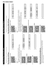
KEH-P2800,P3850 44 Using CD Player (one disc only) This product can control one disc only). Each press changes the Source ... Basic Operation of CD Player 1. Refer to the CD player owner's manual. 2. Raise or lower the volume. 5. Turn the source OFF. Select the CD player source. Turn the source OFF. Select the desired disc. 3. Hold for playback. Note: • The CD player is selected only when a CD is loaded. • If the CD player cannot operate properly...
KEH-P2800,P3850 44 Using CD Player (one disc only) This product can control one disc only). Each press changes the Source ... Basic Operation of CD Player 1. Refer to the CD player owner's manual. 2. Raise or lower the volume. 5. Turn the source OFF. Select the CD player source. Turn the source OFF. Select the desired disc. 3. Hold for playback. Note: • The CD player is selected only when a CD is loaded. • If the CD player cannot operate properly...
Service Manual
Page 45
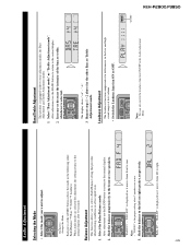
... Bass Adjustment and Treble Adjustment modes. 1. Balance Adjustment This function allows you want to adjust. Increase or decrease the intensity of the AUDIO button selects the mode in the low and high sound ranges at low volume. • Switch the Loudness function ON or OFF. "FAD R15" is selected. KEH-P2800,P3850 45 Audio Adjustment Selecting the Mode • Select the mode you to select a Fader/Balance setting that provides ideal listening conditions in the Audio Adjustment Menu. Each press changes the Mode ... The display...
... Bass Adjustment and Treble Adjustment modes. 1. Balance Adjustment This function allows you want to adjust. Increase or decrease the intensity of the AUDIO button selects the mode in the low and high sound ranges at low volume. • Switch the Loudness function ON or OFF. "FAD R15" is selected. KEH-P2800,P3850 45 Audio Adjustment Selecting the Mode • Select the mode you to select a Fader/Balance setting that provides ideal listening conditions in the Audio Adjustment Menu. Each press changes the Mode ... The display...
Service Manual
Page 46
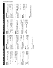
.... KEH-P2800,P3850 Specifications (KEH-P2800/X1M/UC) Specifications (KEH-P3850/X1M/ES) General Power source .......... 14.4 V DC (10.8 - 15.1 V allowable) Grounding system Negative type Max. Maximum power output 40 W × 4 Load impedance 4 Ω (4 - 8 Ω allowable) Preout maximum output level/output impedance 2.2 V/1 kΩ Tone controls (Bass 12 dB (100 Hz) (Treble 12 dB (10 kHz) Loudness contour ........ +10 dB (100 Hz), +7 dB (10 kHz) (volume: -30 dB) Cassette player Tape Compact cassette...
.... KEH-P2800,P3850 Specifications (KEH-P2800/X1M/UC) Specifications (KEH-P3850/X1M/ES) General Power source .......... 14.4 V DC (10.8 - 15.1 V allowable) Grounding system Negative type Max. Maximum power output 40 W × 4 Load impedance 4 Ω (4 - 8 Ω allowable) Preout maximum output level/output impedance 2.2 V/1 kΩ Tone controls (Bass 12 dB (100 Hz) (Treble 12 dB (10 kHz) Loudness contour ........ +10 dB (100 Hz), +7 dB (10 kHz) (volume: -30 dB) Cassette player Tape Compact cassette...


