Service Manual
Page 1
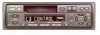
... K-ZZB. For the operations in this model is one of 2M series. - SCHEMATIC DIAGRAM 8 4. PIONEER ELECTRONIC [EUROPE] N.V. DEC. 1998 Printed in Japan EXPLODED VIEWS AND PARTS LIST 2 3. CRT2268 MULTI-CD CONTROL HIGH POWER CASSETTE PLAYER WITH FM/AM TUNER KEH-P2800 KEH-P3850 X1M/ES X1M/UC NOTE: - This service manual does not describe the CD test...
... K-ZZB. For the operations in this model is one of 2M series. - SCHEMATIC DIAGRAM 8 4. PIONEER ELECTRONIC [EUROPE] N.V. DEC. 1998 Printed in Japan EXPLODED VIEWS AND PARTS LIST 2 3. CRT2268 MULTI-CD CONTROL HIGH POWER CASSETTE PLAYER WITH FM/AM TUNER KEH-P2800 KEH-P3850 X1M/ES X1M/UC NOTE: - This service manual does not describe the CD test...
Service Manual
Page 2
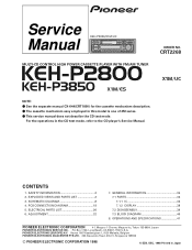
Health & Safety Code Section 25249.6 - EXPLODED VIEWS AND PARTS LIST 2.1 PACKING 63 7 4 5 19 18 17 16 12 9 2 10 8 14 20 1 15 11 13 2 KEH-P2800,P3850 1. If you should not risk trying to do -it is not meant for qualified service technicians; Proposition 65 2. Improperly performed ...and have been trained to cause cancer, birth defects or other reproductive harm. WARNING This product contains lead in solder and certain electrical parts contain chemicals which are not qualified to the state of the product and may void the warranty. you are known to perform the repair...
Health & Safety Code Section 25249.6 - EXPLODED VIEWS AND PARTS LIST 2.1 PACKING 63 7 4 5 19 18 17 16 12 9 2 10 8 14 20 1 15 11 13 2 KEH-P2800,P3850 1. If you should not risk trying to do -it is not meant for qualified service technicians; Proposition 65 2. Improperly performed ...and have been trained to cause cancer, birth defects or other reproductive harm. WARNING This product contains lead in solder and certain electrical parts contain chemicals which are not qualified to the state of the product and may void the warranty. you are known to perform the repair...
Service Manual
Page 3
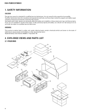
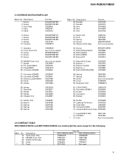
Description 1 Cord Assy 2 Spring 3 Screw Assy 4 Screw * 5 Polyethylene Bag Part.No KEH-P2800/X1M/UC KEH-P3850/X1M/ES CDE5805 CDE5805 CBH1650 CBH1650 CEA2351 CEA2351 CBA1304 CBA1304 CEG-127 CEG-127 6 Screw(x4) 7 Screw(x4) * 8 ... CRD2803 Not used for disassembly. - Language KEH-P2800/X1M/UC CRD2804 English,French,Spanish CRD2805 English,French,Spanish KEH-P3850/X1M/ES CRD2801 English,Spanish,Portuguese(B) CRD2802 Chinese,Arabic CRD2803 English,Spanish,Portuguese(B),Chinese,Arabic 3 Owner's Manual, Installation Manual Model Part No. Screws adjacent to ∇ mark...
Description 1 Cord Assy 2 Spring 3 Screw Assy 4 Screw * 5 Polyethylene Bag Part.No KEH-P2800/X1M/UC KEH-P3850/X1M/ES CDE5805 CDE5805 CBH1650 CBH1650 CEA2351 CEA2351 CBA1304 CBA1304 CEG-127 CEG-127 6 Screw(x4) 7 Screw(x4) * 8 ... CRD2803 Not used for disassembly. - Language KEH-P2800/X1M/UC CRD2804 English,French,Spanish CRD2805 English,French,Spanish KEH-P3850/X1M/ES CRD2801 English,Spanish,Portuguese(B) CRD2802 Chinese,Arabic CRD2803 English,Spanish,Portuguese(B),Chinese,Arabic 3 Owner's Manual, Installation Manual Model Part No. Screws adjacent to ∇ mark...
Service Manual
Page 5
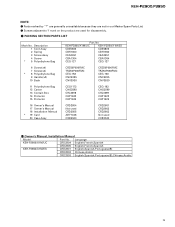
...Conductor CNV5752 68 Case Assy CXB3520 69 Transistor(Q804) 2SD2396 70 Cassette Mechanism Assy EXK3450 71 Fuse(FU951)(10A) 72 IC(IC501) * 73 Cord CEK1136 TDA7384 See Contrast table(2) (2) CONTRAST TABLE KEH-P2800/X1M/UC and KEH-P3850/X1M/ES are constructed the same except for the following:... Mark No. 12 16 45 58 * 73 Description Tuner Amp Unit FM/AM Tuner Unit Detach Grille Assy Grille Cord Part No. KEH-P2800/X1M/UC KEH-P3850/X1M/ES CWM6276 CWM6349 CWE1467 CWE1486 CXB3369 CXB3375 CNS5200 CNS5201 CDC1043 Not used 5 Description 1 Screw 2 Screw 3 Cord Assy 4...
...Conductor CNV5752 68 Case Assy CXB3520 69 Transistor(Q804) 2SD2396 70 Cassette Mechanism Assy EXK3450 71 Fuse(FU951)(10A) 72 IC(IC501) * 73 Cord CEK1136 TDA7384 See Contrast table(2) (2) CONTRAST TABLE KEH-P2800/X1M/UC and KEH-P3850/X1M/ES are constructed the same except for the following:... Mark No. 12 16 45 58 * 73 Description Tuner Amp Unit FM/AM Tuner Unit Detach Grille Assy Grille Cord Part No. KEH-P2800/X1M/UC KEH-P3850/X1M/ES CWM6276 CWM6349 CWE1467 CWE1486 CXB3369 CXB3375 CNS5200 CNS5201 CDC1043 Not used 5 Description 1 Screw 2 Screw 3 Cord Assy 4...
Service Manual
Page 7
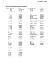
KEH-P2800,P3850 - BSZ23P050FMC CBG1003 CKS2829 EBA1038 EBA1037 Mark No. Description 46 Gear 47 Gear 48 Gear 49 Gear 50 Lever Part No. Description 1 Screw 2 Washer 3 Connector(CN1) 4 Screw(M2x5) 5 Screw(M2x2.5) Part No. CASSETTE MECHANISM ASSY SECTION PARTS LIST Mark No. ENV1475 ENV1512 ENV1513 ENV1502 ENV1480 6 Spring 7 Spring 8 Spring 9 Spring 10 Spring EBH1554 EBH1555 EBH1556 EBH1603...
KEH-P2800,P3850 - BSZ23P050FMC CBG1003 CKS2829 EBA1038 EBA1037 Mark No. Description 46 Gear 47 Gear 48 Gear 49 Gear 50 Lever Part No. Description 1 Screw 2 Washer 3 Connector(CN1) 4 Screw(M2x5) 5 Screw(M2x2.5) Part No. CASSETTE MECHANISM ASSY SECTION PARTS LIST Mark No. ENV1475 ENV1512 ENV1513 ENV1502 ENV1480 6 Spring 7 Spring 8 Spring 9 Spring 10 Spring EBH1554 EBH1555 EBH1556 EBH1603...
Service Manual
Page 8
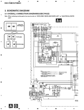
A-a Large size A-a A-b SCH diagram B FM/AM TUNER UNIT CWE1467(/UC) CWE1486(/ES) A-a A-b Guide page B A-a A-b Detailed page 220 C D CASSETTE 24dBs PCB D 8 AD 1 2 3 4 SCHEMATIC DIAGRAM 3.1 OVERALL CONNECTION DIAGRAM(GUIDE PAGE) A Note: When ordering service parts, be sure to refer to "EXPLODED VIEWS AND PARTS LIST" or "ELECTRICAL PARTS LIST". 1 2 3 4 KEH-P2800,P3850 3.
A-a Large size A-a A-b SCH diagram B FM/AM TUNER UNIT CWE1467(/UC) CWE1486(/ES) A-a A-b Guide page B A-a A-b Detailed page 220 C D CASSETTE 24dBs PCB D 8 AD 1 2 3 4 SCHEMATIC DIAGRAM 3.1 OVERALL CONNECTION DIAGRAM(GUIDE PAGE) A Note: When ordering service parts, be sure to refer to "EXPLODED VIEWS AND PARTS LIST" or "ELECTRICAL PARTS LIST". 1 2 3 4 KEH-P2800,P3850 3.
Service Manual
Page 18
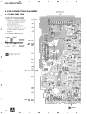
For further information for several destination. PCB CONNECTION DIAGRAM A 4.1 TUNER AMP UNIT NOTE FOR PCB DIAGRAMS 1. Viewpoint of PCB diagrams Connector Capacitor SIDE A B P.C.Board Chip Part SIDE B A TUNER AMP UNIT 3 4 CORD ASSY C D A 18 C CN901 1 2 3 4 The parts mounted on this PCB include all necessary parts for respective destinations, be sure to check with the schematic diagram. 2. 1 2 KEH-P2800,P3850 4.
For further information for several destination. PCB CONNECTION DIAGRAM A 4.1 TUNER AMP UNIT NOTE FOR PCB DIAGRAMS 1. Viewpoint of PCB diagrams Connector Capacitor SIDE A B P.C.Board Chip Part SIDE B A TUNER AMP UNIT 3 4 CORD ASSY C D A 18 C CN901 1 2 3 4 The parts mounted on this PCB include all necessary parts for respective destinations, be sure to check with the schematic diagram. 2. 1 2 KEH-P2800,P3850 4.
Service Manual
Page 34
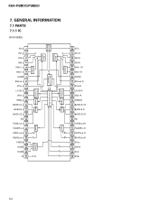
... 1 2 3 4 5 6 7 8 9 10 11 12 13 14 15 16 17 18 19 20 21 22 23 24 Isolator Supply A Power Fader Volume, Loudness Treble Bass KEH-P2800,P3850 7. GENERAL INFORMATION 7.1 PARTS 7.1.1 IC SN761029DL AVcc IN1-L IN2-L IN3-L IN4(+)-L IN4(-)-L AGND SWout-L ZCin-L LOUD-L VRin-L TREB-L BASS-C1-L BASS-R-L BASS-C2-L NC TONEout-L FADERin-L FRNTout-L REARout...
... 1 2 3 4 5 6 7 8 9 10 11 12 13 14 15 16 17 18 19 20 21 22 23 24 Isolator Supply A Power Fader Volume, Loudness Treble Bass KEH-P2800,P3850 7. GENERAL INFORMATION 7.1 PARTS 7.1.1 IC SN761029DL AVcc IN1-L IN2-L IN3-L IN4(+)-L IN4(-)-L AGND SWout-L ZCin-L LOUD-L VRin-L TREB-L BASS-C1-L BASS-R-L BASS-C2-L NC TONEout-L FADERin-L FRNTout-L REARout...

