Owner's Manual
Page 3
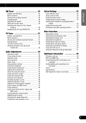
... 35 Changing band 36 Switching the display 36 XM tuner function menu 36 Switching the channel in the channel category 36 Displaying the ID code (RADIO ID 36 TV Tuner 37 Display and indicators 37 Basic operation 37 Storing and recalling broadcast stations .......... 37 Changing band 38 TV tuner function menu...
... 35 Changing band 36 Switching the display 36 XM tuner function menu 36 Switching the channel in the channel category 36 Displaying the ID code (RADIO ID 36 TV Tuner 37 Display and indicators 37 Basic operation 37 Storing and recalling broadcast stations .......... 37 Changing band 38 TV tuner function menu...
Owner's Manual
Page 8
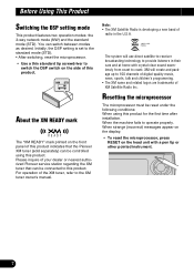
...refer to operate properly. For operation of your dealer or nearest authorized Pioneer service station regarding the XM tuner that the Pioneer XM tuner (sold separately) can switch between modes as desired. Note: • The XM Satellite Radio is set to the standard mode (STD). • After switching... When strange (incorrect) messages appear on the display. • To reset the microprocessor, press RESET on the side of XM Satellite Radio Inc. The system will create and package up to coast. Before Using This Product Switching the DSP setting mode This product features two ...
...refer to operate properly. For operation of your dealer or nearest authorized Pioneer service station regarding the XM tuner that the Pioneer XM tuner (sold separately) can switch between modes as desired. Note: • The XM Satellite Radio is set to the standard mode (STD). • After switching... When strange (incorrect) messages appear on the display. • To reset the microprocessor, press RESET on the side of XM Satellite Radio Inc. The system will create and package up to coast. Before Using This Product Switching the DSP setting mode This product features two ...
Owner's Manual
Page 32
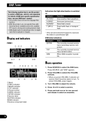
... becomes easier to select a service. 5. Press 2 or 3 to turn. Press SOURCE until "DAB" appears. 2. Press and hold 2 or 3 for one second and release to digital radio that broadcasts in parentheses light. Display and indicators FORM 1 q we rt yu FORM 2 q i o!0 uty w r o i !1 qBand wTRFC indicator eNEWS indicator rTXT indicator tPreset number yANNC indicator...
... becomes easier to select a service. 5. Press 2 or 3 to turn. Press SOURCE until "DAB" appears. 2. Press and hold 2 or 3 for one second and release to digital radio that broadcasts in parentheses light. Display and indicators FORM 1 q we rt yu FORM 2 q i o!0 uty w r o i !1 qBand wTRFC indicator eNEWS indicator rTXT indicator tPreset number yANNC indicator...

Owner's Manual
Page 37
...within about 30 seconds, the display is automatically returned. Switching the channel in the selected channel category. Press BAND to select the channel category RADIO ID. Channel category select mode • Press 5 or ∞ to cancel the channel select mode. 4. Press 2 or 3 to...repeatedly to switch between the following functions: q q chMODE (channel select) Press chMODE repeatedly to select channel mode. 2. Displaying the ID code (RADIO ID) Channel number select mode • Press 2 or 3 to select the desired band. ENGLISH ESPAÑOL DEUTSCH Changing band •...
...within about 30 seconds, the display is automatically returned. Switching the channel in the selected channel category. Press BAND to select the channel category RADIO ID. Channel category select mode • Press 5 or ∞ to cancel the channel select mode. 4. Press 2 or 3 to...repeatedly to switch between the following functions: q q chMODE (channel select) Press chMODE repeatedly to select channel mode. 2. Displaying the ID code (RADIO ID) Channel number select mode • Press 2 or 3 to select the desired band. ENGLISH ESPAÑOL DEUTSCH Changing band •...
Other Manual
Page 3
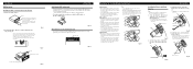
...of the head unit become aligned (are used, this unit may result in the bracket. 10 Fig. 9 1S1crew Fig. 10 D13ashboard or Console Factory radio mounting bra1c2ket Fig. 11 Switching the DSP setting mode This product features two operation modes: the 3-way network mode (NW) and the standard mode ...(STD). Always attach this unit to the factory radio mounting bracket. (Fig. 10) (Fig. 11) Select a position where the screw holes of the bracket and the screw holes of the unit 1. ...
...of the head unit become aligned (are used, this unit may result in the bracket. 10 Fig. 9 1S1crew Fig. 10 D13ashboard or Console Factory radio mounting bra1c2ket Fig. 11 Switching the DSP setting mode This product features two operation modes: the 3-way network mode (NW) and the standard mode ...(STD). Always attach this unit to the factory radio mounting bracket. (Fig. 10) (Fig. 11) Select a position where the screw holes of the bracket and the screw holes of the unit 1. ...


