
Other Manual
Page 3
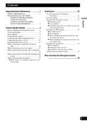
... THIS MANUAL 1 PLEASE READ ALL OF THESE INSTRUCTIONS REGARDING YOUR NAVIGATION SYSTEM AND RETAIN THEM FOR FUTURE REFERENCE 1 Connecting the System 3 Before installing this navigation system 4 To prevent damage 5 Parts supplied 6 Connecting the system 7 Connecting the multi-channel processor 9 Connecting the power cord...electromagnetic interference 21 Before installing 21 Installing this Navigation System 30 Español Deutsch Français Italiano Nederlands 2 Installation using a rear display connected to separately sold power amp 15 When connecting a rear view camera ...
... THIS MANUAL 1 PLEASE READ ALL OF THESE INSTRUCTIONS REGARDING YOUR NAVIGATION SYSTEM AND RETAIN THEM FOR FUTURE REFERENCE 1 Connecting the System 3 Before installing this navigation system 4 To prevent damage 5 Parts supplied 6 Connecting the system 7 Connecting the multi-channel processor 9 Connecting the power cord...electromagnetic interference 21 Before installing 21 Installing this Navigation System 30 Español Deutsch Français Italiano Nederlands 2 Installation using a rear display connected to separately sold power amp 15 When connecting a rear view camera ...

Other Manual
Page 5
...by cutting the insulation of the power supply lead of this navigation system • This navigation system is ground. Altering the antenna cable could result in a short circuit or malfunction and permanent damage to the navigation system. • Do not cut the GPS antenna cable to ... product together with a 12-volt battery and negative grounding. Check the battery voltage of high-current products such as power amps. Before installing this navigation system. For example, you do, the protection circuit (fuse holder, fuse resister or filter, etc.) may become damaged, resulting...
...by cutting the insulation of the power supply lead of this navigation system • This navigation system is ground. Altering the antenna cable could result in a short circuit or malfunction and permanent damage to the navigation system. • Do not cut the GPS antenna cable to ... product together with a 12-volt battery and negative grounding. Check the battery voltage of high-current products such as power amps. Before installing this navigation system. For example, you do, the protection circuit (fuse holder, fuse resister or filter, etc.) may become damaged, resulting...

Other Manual
Page 6
...ACC OFF). • When replacing the fuse, be sure to the ≠ side of the speaker lead on this navigation system. • If the RCA pin jack on this navigation system will not be stowed or turned off only when the ignition switch is turned off by following the instructions below. - Insulate...blue port, black to black, etc. • Refer to the power terminal of the connector. • This navigation system cannot be sure not to connect the blue lead to an external power amp's system remote control terminal (max. 300 mA 12 V DC). Change the source from radio (AM or FM) to ...
...ACC OFF). • When replacing the fuse, be sure to the ≠ side of the speaker lead on this navigation system. • If the RCA pin jack on this navigation system will not be stowed or turned off only when the ignition switch is turned off by following the instructions below. - Insulate...blue port, black to black, etc. • Refer to the power terminal of the connector. • This navigation system cannot be sure not to connect the blue lead to an external power amp's system remote control terminal (max. 300 mA 12 V DC). Change the source from radio (AM or FM) to ...

Other Manual
Page 16
Connecting the System When connecting to Auto-antenna control terminal. 15 Do not connect this lead to separately sold power amp Subwoofer output or non-fading output (SUBWOOFER OUTPUT or NON-FADING OUTPUT) 23 cm (9 in.) RCA connector 1 Rear output (REAR OUTPUT) 15 cm (5-7/8 in.) The navigation unit Front output (FRONT OUTPUT) 15 cm (5-7/8 in.) 15 cm (5-7/8 in.) Blue/white To system control terminal of the power amp (max. 300 mA 12 V DC).
Connecting the System When connecting to Auto-antenna control terminal. 15 Do not connect this lead to separately sold power amp Subwoofer output or non-fading output (SUBWOOFER OUTPUT or NON-FADING OUTPUT) 23 cm (9 in.) RCA connector 1 Rear output (REAR OUTPUT) 15 cm (5-7/8 in.) The navigation unit Front output (FRONT OUTPUT) 15 cm (5-7/8 in.) 15 cm (5-7/8 in.) Blue/white To system control terminal of the power amp (max. 300 mA 12 V DC).
Other Manual
Page 17
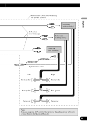
English Perform these connections when using the optional amplifier. RCA cables (sold separately) Power amp (sold separately) Power amp (sold separately) Power amp (sold separately) Español Deutsch Français Italiano System remote control Left + Front speaker ≠ Right + Front speaker ≠ + Rear speaker ≠ + Rear speaker ≠ + Subwoofer ≠ + Subwoofer ≠ Note: You can change the RCA output of the subwoofer depending on your subwoofer system. (Refer to the Operation Manual.) 16 Nederlands
English Perform these connections when using the optional amplifier. RCA cables (sold separately) Power amp (sold separately) Power amp (sold separately) Power amp (sold separately) Español Deutsch Français Italiano System remote control Left + Front speaker ≠ Right + Front speaker ≠ + Rear speaker ≠ + Rear speaker ≠ + Subwoofer ≠ + Subwoofer ≠ Note: You can change the RCA output of the subwoofer depending on your subwoofer system. (Refer to the Operation Manual.) 16 Nederlands


