Owner's Manual
Page 2
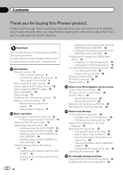
... USB storage device 19 - Ejecting an SD memory card (for AVIC-Z130BT) 15 - Disconnecting your model properly. Viewing information about a specified location 28 - How to use this Pioneer product. Ejecting an SD memory card (for AVIC- Plugging in the examples may be changed without notice for performance... and termination 20 On first-time startup 20 Regular startup 21 How to erasure 11 Basic operation Checking part names and functions 12 - Inserting an SD memory card (for AVIC-X930BT and AVIC-X9310BT) 16 - Selecting the shortcut 23 - Enlarged map of the map 27 -
... USB storage device 19 - Ejecting an SD memory card (for AVIC-Z130BT) 15 - Disconnecting your model properly. Viewing information about a specified location 28 - How to use this Pioneer product. Ejecting an SD memory card (for AVIC- Plugging in the examples may be changed without notice for performance... and termination 20 On first-time startup 20 Regular startup 21 How to erasure 11 Basic operation Checking part names and functions 12 - Inserting an SD memory card (for AVIC-X930BT and AVIC-X9310BT) 16 - Selecting the shortcut 23 - Enlarged map of the map 27 -

Owner's Manual
Page 12
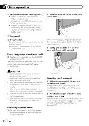
Chapter 02 Basic operation Checking part names and functions This chapter gives information about the names of the parts and the main features using the buttons. 1 2 34 5 67 AVIC-Z130BT (with the LCD panel closed) 8 9 AVIC-Z130BT (with the LCD panel open) 12 En
Chapter 02 Basic operation Checking part names and functions This chapter gives information about the names of the parts and the main features using the buttons. 1 2 34 5 67 AVIC-Z130BT (with the LCD panel closed) 8 9 AVIC-Z130BT (with the LCD panel open) 12 En
Owner's Manual
Page 14
... navigation system. 2 Push the lower part of Multi-control to remove the front panel from the navigation system. Keep the front panel out of reach of Multi-control to discourage theft, as the panel could be operated while the front panel is available for AVIC-X930BT and AVIC-X9310BT. dren to prevent them from...
... navigation system. 2 Push the lower part of Multi-control to remove the front panel from the navigation system. Keep the front panel out of reach of Multi-control to discourage theft, as the panel could be operated while the front panel is available for AVIC-X930BT and AVIC-X9310BT. dren to prevent them from...
Owner's Manual
Page 92
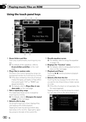
... list Touching the key displays the list which lets you see the list of various media file types, all tracks or files within the current part ("CD" or "ROM") are played randomly. = For details, refer to the next file. Tapping a folder on a disc. Chapter 18 Playing music files on ROM Using...
... list Touching the key displays the list which lets you see the list of various media file types, all tracks or files within the current part ("CD" or "ROM") are played randomly. = For details, refer to the next file. Tapping a folder on a disc. Chapter 18 Playing music files on ROM Using...

Owner's Manual
Page 165
The "Volume Settings" screen appears. 3 Touch [+] or [-] to Checking part names and functions on page 162. 2 Touch [Volume]. Guidance This setting controls the guidance volume of the route guidance and the beep sound. 1 Display the "..." screen. = For details, refer to Displaying the screen for system settings on page 12. # If you touch the key next to Displaying the screen for AVIC-Z130BT only. 4 To finish the setting, touch [OK]. p Volume of the AV source is adjusted by the VOL (+/-) button or Multi-control. = For details, refer...
The "Volume Settings" screen appears. 3 Touch [+] or [-] to Checking part names and functions on page 162. 2 Touch [Volume]. Guidance This setting controls the guidance volume of the route guidance and the beep sound. 1 Display the "..." screen. = For details, refer to Displaying the screen for system settings on page 12. # If you touch the key next to Displaying the screen for AVIC-Z130BT only. 4 To finish the setting, touch [OK]. p Volume of the AV source is adjusted by the VOL (+/-) button or Multi-control. = For details, refer...
Instruction Manual
Page 2
Installation notes 21 - Parts supplied 26 - AVIC-X930BT, AVIC-X9310BT 6 Connecting the system 8 Connecting the power cord (1) 10 Connecting the power cord (2) 12 When connecting to rear video output 18 When connecting the external ... front panel 23 Installing the GPS antenna 24 - When installing the antenna inside the vehicle (on the side of the navigation unit 22 2 En - Parts supplied 22 - AVIC-Z130BT 6 - Installation notes 24 - Installation using a rear display connected to separately sold power amp 14 When connecting a rear view camera 16 When connecting the...
Installation notes 21 - Parts supplied 26 - AVIC-X930BT, AVIC-X9310BT 6 Connecting the system 8 Connecting the power cord (1) 10 Connecting the power cord (2) 12 When connecting to rear video output 18 When connecting the external ... front panel 23 Installing the GPS antenna 24 - When installing the antenna inside the vehicle (on the side of the navigation unit 22 2 En - Parts supplied 22 - AVIC-Z130BT 6 - Installation notes 24 - Installation using a rear display connected to separately sold power amp 14 When connecting a rear view camera 16 When connecting the...

Instruction Manual
Page 4
...with cable clamps or electrical tape. Do not shorten any of the lead will not obstruct or hinder driving. ! Use this unit with metal parts, short-circuiting can occur, resulting in such so that the cables and wires will be exposed to high temperatures. Do not cut the GPS.... Before installing this unit. 4 En To avoid shorts in a fire or malfunction. ! Do not directly connect the yellow lead of the vehicle's moving parts, especially the steering wheel, shift lever, parking brake, sliding seat tracks, doors, or any leads. Do not route wires where they will be sure to...
...with cable clamps or electrical tape. Do not shorten any of the lead will not obstruct or hinder driving. ! Use this unit with metal parts, short-circuiting can occur, resulting in such so that the cables and wires will be exposed to high temperatures. Do not cut the GPS.... Before installing this unit. 4 En To avoid shorts in a fire or malfunction. ! Do not directly connect the yellow lead of the vehicle's moving parts, especially the steering wheel, shift lever, parking brake, sliding seat tracks, doors, or any leads. Do not route wires where they will be sure to...

Instruction Manual
Page 5
... connector to the blue port, black to insulate all unused speaker leads, which if left uncovered may pull it could result in the car) Metal parts of the car's body. Be sure to connect the * side of the speaker lead to the * side of this unit or any other units, then... make sure to metal parts of car's body ! OF OF Other devices (Another electronic device in fire generation of the rating prescribed on (ACC ON), a control signal is output through...
... connector to the blue port, black to insulate all unused speaker leads, which if left uncovered may pull it could result in the car) Metal parts of the car's body. Be sure to connect the * side of the speaker lead to the * side of this unit or any other units, then... make sure to metal parts of car's body ! OF OF Other devices (Another electronic device in fire generation of the rating prescribed on (ACC ON), a control signal is output through...
Instruction Manual
Page 6
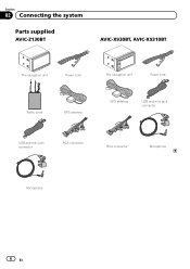
Section 02 Connecting the system Parts supplied AVIC-Z130BT AVIC-X930BT, AVIC-X9310BT The navigation unit Power cord The navigation unit Power cord Traffic tuner GPS antenna GPS antenna USB and mini-jack connector USB and mini-jack connector RCA connector RCA connector Microphone Microphone 6 En
Section 02 Connecting the system Parts supplied AVIC-Z130BT AVIC-X930BT, AVIC-X9310BT The navigation unit Power cord The navigation unit Power cord Traffic tuner GPS antenna GPS antenna USB and mini-jack connector USB and mini-jack connector RCA connector RCA connector Microphone Microphone 6 En
Instruction Manual
Page 20
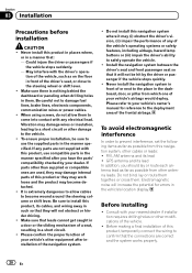
...such so that the connections are correct and the system works properly. 20 En GPS antenna and its lead In addition, you have the parts' compatibility checked by the driver or passenger if the vehicle stops quickly. ! May interfere with this navigation system, other than supplied or ...as far as possible from other damage to the steering wheel or shift lever. ! Electromagnetic noise will not be sure to become detached. ! If any parts are used, they may (i) obstruct the driver's vision, (ii) impair the performance of the driver's seat, or close to the vehicle. ! Install...
...such so that the connections are correct and the system works properly. 20 En GPS antenna and its lead In addition, you have the parts' compatibility checked by the driver or passenger if the vehicle stops quickly. ! May interfere with this navigation system, other than supplied or ...as far as possible from other damage to the steering wheel or shift lever. ! Electromagnetic noise will not be sure to become detached. ! If any parts are used, they may (i) obstruct the driver's vision, (ii) impair the performance of the driver's seat, or close to the vehicle. ! Install...
Instruction Manual
Page 22
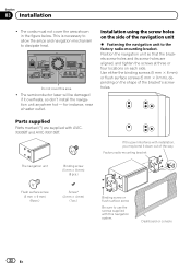
Parts supplied Parts marked (*) are aligned, and tighten the screws at three or four locations on the shape of the navigation unit % Fastening the navigation unit to dissipate ... - for instance, near a heater outlet. Installation using the screw holes on the side of the bracket's screw holes. If the pawl interferes with AVICX930BT and AVIC-X9310BT. The cords must not cover the area shown in the figure below. This is necessary to allow the amps and navigation mechanism to the...
Parts supplied Parts marked (*) are aligned, and tighten the screws at three or four locations on the shape of the navigation unit % Fastening the navigation unit to dissipate ... - for instance, near a heater outlet. Installation using the screw holes on the side of the bracket's screw holes. If the pawl interferes with AVICX930BT and AVIC-X9310BT. The cords must not cover the area shown in the figure below. This is necessary to allow the amps and navigation mechanism to the...

Instruction Manual
Page 24
... to use an extension to make it longer. Do not paint the GPS antenna, as possible. This would reduce the sensitivity of the GPS antenna. ! Parts supplied GPS antenna Installation notes !
... to use an extension to make it longer. Do not paint the GPS antenna, as possible. This would reduce the sensitivity of the GPS antenna. ! Parts supplied GPS antenna Installation notes !

Instruction Manual
Page 26
Installing the microphone ! Parts supplied Microphone Microphone clip Double-sided tape Mounting on the outside of the vehicle. Some models use window glass that does not allow signals from ...
Installing the microphone ! Parts supplied Microphone Microphone clip Double-sided tape Mounting on the outside of the vehicle. Some models use window glass that does not allow signals from ...


