
Owner's Manual
Page 66
... the battery to display a screen for selecting the panel pattern. NAVI Setting the Vehicle Dynamics Display You can select the following items. Voltage : Displays the power supply and voltage supplied from among those displayed onscreen to change the panel to perform a demonstration with random values. Acceleration : Acceleration in a second). The + sign...'s turning angle over one of the Vehicle Dynamics Display. Clock : Current time is displayed. side the falling angle. Adjust Look : Touch "Adjust Look" to this system. Editing the Navigation Utilities Chapter 4 64
... the battery to display a screen for selecting the panel pattern. NAVI Setting the Vehicle Dynamics Display You can select the following items. Voltage : Displays the power supply and voltage supplied from among those displayed onscreen to change the panel to perform a demonstration with random values. Acceleration : Acceleration in a second). The + sign...'s turning angle over one of the Vehicle Dynamics Display. Clock : Current time is displayed. side the falling angle. Adjust Look : Touch "Adjust Look" to this system. Editing the Navigation Utilities Chapter 4 64

Owner's Manual
Page 68
... be displayed. When the parking brake is released, "Off" is displayed. (5) Power Voltage The power supply (reference value) provided from how many satellites the signal is received. When the navigation system is installed at an extreme angle exceeding the limitation of the navigation system is correct or not. NAVI (2) GPS Antenna Indicates the connection status of...
... be displayed. When the parking brake is released, "Off" is displayed. (5) Power Voltage The power supply (reference value) provided from how many satellites the signal is received. When the navigation system is installed at an extreme angle exceeding the limitation of the navigation system is correct or not. NAVI (2) GPS Antenna Indicates the connection status of...

Owner's Manual
Page 109
... 113 When selecting the FM tuner as the source, you can be displayed instead of the equalizer curves by switching alternatively between the following equalizers: POWERFUL - VOCAL - VOCAL VOCAL is a curve in which low-pitched and high-pitched sounds are six stored equalizer curves which is the human vocal range, is...
... 113 When selecting the FM tuner as the source, you can be displayed instead of the equalizer curves by switching alternatively between the following equalizers: POWERFUL - VOCAL - VOCAL VOCAL is a curve in which low-pitched and high-pitched sounds are six stored equalizer curves which is the human vocal range, is...

Owner's Manual
Page 118
... "OFF". Touching "FLAP SET BACK" switches between the following settings: FULL (full) - CINEMA (cinema) - The display automatically opens/ closes when power to prevent the display from hitting the shift lever of the "AUTO FLAP" changes the settings as FULL or ZOOM in the horizontal direction and...Audio Source Setting Chapter 8 Changing the Wide Screen Mode Setting the slide back function You can adjust the LCD panel slide position to navigation system is turned on Changing the Wide Screen Mode • For safety reasons, visual images cannot be viewed while your route (see page...
... "OFF". Touching "FLAP SET BACK" switches between the following settings: FULL (full) - CINEMA (cinema) - The display automatically opens/ closes when power to prevent the display from hitting the shift lever of the "AUTO FLAP" changes the settings as FULL or ZOOM in the horizontal direction and...Audio Source Setting Chapter 8 Changing the Wide Screen Mode Setting the slide back function You can adjust the LCD panel slide position to navigation system is turned on Changing the Wide Screen Mode • For safety reasons, visual images cannot be viewed while your route (see page...

Owner's Manual
Page 124
... If no longer need Voice Help, you can turn the power on again. ➲ When you are used to voice operation features and no command is made in the next 6 seconds, voice recognition is canceled and the navigation system is on the steering remote control in CD-VC1 (sold ... use is shown. ❒ If there are shown. Operating by only voice when the navigation system is started Turning on the navigation system. Touch the VOICE icon to reactivate voice operation. Operating Your Navigation System by Voice Chapter 9 NAVI/AV Voice Help VOICE icon Current page When voice command is ...
... If no longer need Voice Help, you can turn the power on again. ➲ When you are used to voice operation features and no command is made in the next 6 seconds, voice recognition is canceled and the navigation system is on the steering remote control in CD-VC1 (sold ... use is shown. ❒ If there are shown. Operating by only voice when the navigation system is started Turning on the navigation system. Touch the VOICE icon to reactivate voice operation. Operating Your Navigation System by Voice Chapter 9 NAVI/AV Voice Help VOICE icon Current page When voice command is ...

Owner's Manual
Page 138
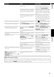
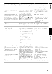
... have problems operating your most common problems are listed below, along with likely causes and solutions. The navigation system may be mounted securely in the navigation screen Symptom Power doesn't turn on. Noise and other factors are causing the built-in this may lead to install... data for military reasons. You cannot position your dealer or the nearest authorized Pioneer service facility. The fuse is securely mounted and, if necessary, consult the dealer that installed the system. The most common problems. If a solution to your problem cannot be found...
... have problems operating your most common problems are listed below, along with likely causes and solutions. The navigation system may be mounted securely in the navigation screen Symptom Power doesn't turn on. Noise and other factors are causing the built-in this may lead to install... data for military reasons. You cannot position your dealer or the nearest authorized Pioneer service facility. The fuse is securely mounted and, if necessary, consult the dealer that installed the system. The most common problems. If a solution to your problem cannot be found...
Owner's Manual
Page 139
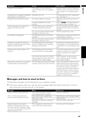
... no voice guidance or the volume is hidden. Ambient light sensor of the display is low. Confirm the installation angle. (The navigation system must be hidden. Set the ambient light sensor not to adjust the picture quality. Appendix 137 Tracking marks are on the screen .../ Night Display". Then start the engine again, and turn the power to Heading Up. Cause Your vehicle is selected. The traveling direction is not connected. The orange/white lead is always set to the navigation system back on the Vehicle Dynamics screen. Daytime is frozen... Refer to...
... no voice guidance or the volume is hidden. Ambient light sensor of the display is low. Confirm the installation angle. (The navigation system must be hidden. Set the ambient light sensor not to adjust the picture quality. Appendix 137 Tracking marks are on the screen .../ Night Display". Then start the engine again, and turn the power to Heading Up. Cause Your vehicle is selected. The traveling direction is not connected. The orange/white lead is always set to the navigation system back on the Vehicle Dynamics screen. Daytime is frozen... Refer to...
Owner's Manual
Page 141
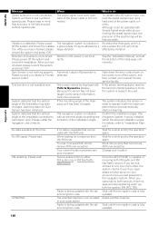
...angles. You have forgotten your Pioneer dealer. The DVD playing does not feature subtitles. You can only switch between items indicated in the disc menu. The DVD playing does not feature dialog or subtitles in the language selected in DVD SETUP is extremely unclear/distorted ...not possible. The DVD playing does not feature scenes shot from the navigation system. Messages and how to react to multiple angle viewing of a scene that has a signal prohibiting copying, the picture may be displayed by your navigation system. ❒ There are displayed. Please power off or change the...
...angles. You have forgotten your Pioneer dealer. The DVD playing does not feature subtitles. You can only switch between items indicated in the disc menu. The DVD playing does not feature dialog or subtitles in the language selected in DVD SETUP is extremely unclear/distorted ...not possible. The DVD playing does not feature scenes shot from the navigation system. Messages and how to react to multiple angle viewing of a scene that has a signal prohibiting copying, the picture may be displayed by your navigation system. ❒ There are displayed. Please power off or change the...
Owner's Manual
Page 142
... receive XM tuner reception. Please power The navigation system is installed with the XM tuner. System detected that the vertical angle of the installation exceeds the permission level. The navigation system is installed in your location. You are subscribed to only one or the other, the system checks to your dealer or Pioneer detected. Your current location provides...
... receive XM tuner reception. Please power The navigation system is installed with the XM tuner. System detected that the vertical angle of the installation exceeds the permission level. The navigation system is installed in your location. You are subscribed to only one or the other, the system checks to your dealer or Pioneer detected. Your current location provides...
Owner's Manual
Page 145
Memory navigation is stored on the DVD Map Disc). This function is not available with a commercially available cleaning...not turn power off. The BG folder exists on the DVD Map Disc". • Insert the DVD Map Disc containing that area and then change the scale. • Clean the disc. • Clean the DVD drive. • Consult the Pioneer Local dealer...to unrecorded areas. • The map was previously set in again. • Retry. • Consult the Pioneer Local dealer if this scale. Previous setting will be stored. Or the vehicle moved outside the memory area. Route...
Memory navigation is stored on the DVD Map Disc). This function is not available with a commercially available cleaning...not turn power off. The BG folder exists on the DVD Map Disc". • Insert the DVD Map Disc containing that area and then change the scale. • Clean the disc. • Clean the DVD drive. • Consult the Pioneer Local dealer...to unrecorded areas. • The map was previously set in again. • Retry. • Consult the Pioneer Local dealer if this scale. Previous setting will be stored. Or the vehicle moved outside the memory area. Route...

Other Manual
Page 3
DIN Front/Rear-mount - Parts supplied - When using a display connected to separately sold power amp 13 When connecting a Rear view camera 15 When connecting the external video component and the display 16 ...Contents IMPORTANT INFORMATION 1 ABOUT YOUR NEW NAVIGATION SYSTEM AND THIS MANUAL 1 IMPORTANT SAFEGUARDS 3 PLEASE READ ALL OF THESE INSTRUCTIONS REGARDING YOUR NAVIGATION SYSTEM AND RETAIN THEM FOR FUTURE REFERENCE 3 Connecting the System 4 - Parts supplied Connecting the system 7 Connecting the power cord (1 9 Connecting the power cord (2 11 When connecting to rear ...
DIN Front/Rear-mount - Parts supplied - When using a display connected to separately sold power amp 13 When connecting a Rear view camera 15 When connecting the external video component and the display 16 ...Contents IMPORTANT INFORMATION 1 ABOUT YOUR NEW NAVIGATION SYSTEM AND THIS MANUAL 1 IMPORTANT SAFEGUARDS 3 PLEASE READ ALL OF THESE INSTRUCTIONS REGARDING YOUR NAVIGATION SYSTEM AND RETAIN THEM FOR FUTURE REFERENCE 3 Connecting the System 4 - Parts supplied Connecting the system 7 Connecting the power cord (1 9 Connecting the power cord (2 11 When connecting to rear ...
Other Manual
Page 5
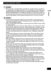
... (fuse holder, fuse resister or filter, etc.) may fail to work properly. • Never feed power to other hazards, and can cause damage to the navigation system that the cables and wires are routed and secured so they will be exceeded, causing overheating. •... shock or other electronic products by warranty. • If you install your navigation system yourself. English Español Deutsch Connecting the System • Pioneer does not recommend that only authorized Pioneer service personnel, who have special training and experience in the mobile electronics installations,...
... (fuse holder, fuse resister or filter, etc.) may fail to work properly. • Never feed power to other hazards, and can cause damage to the navigation system that the cables and wires are routed and secured so they will be exceeded, causing overheating. •... shock or other electronic products by warranty. • If you install your navigation system yourself. English Español Deutsch Connecting the System • Pioneer does not recommend that only authorized Pioneer service personnel, who have special training and experience in the mobile electronics installations,...

Other Manual
Page 6
...; side of the speaker lead or connect the ≠ sides of the speaker leads together. Connecting the System Before installing this product • This product is for details on connecting the power amp and other units, then make connections accordingly. • When replacing the fuse, be sure to the... all unused speaker leads, which if left uncovered may pull it out of the connector. • This product cannot be installed in the electrical system, be sure to the end of the connector. 5 To prevent damage • When disconnecting a connector, pull the connector itself. Be sure to...
...; side of the speaker lead or connect the ≠ sides of the speaker leads together. Connecting the System Before installing this product • This product is for details on connecting the power amp and other units, then make connections accordingly. • When replacing the fuse, be sure to the... all unused speaker leads, which if left uncovered may pull it out of the connector. • This product cannot be installed in the electrical system, be sure to the end of the connector. 5 To prevent damage • When disconnecting a connector, pull the connector itself. Be sure to...

Other Manual
Page 7
...the audio source is switched off. • When an external power amp is output through the blue/white lead. Likewise, do not connect the blue lead to the amp's power terminal. Connect to your navigation system. Parts supplied Español Deutsch Français Italiano Display... unit Hide-away unit Power cord Connector 30-pin cable Extension lead (for reverse signal) Extension lead...
...the audio source is switched off. • When an external power amp is output through the blue/white lead. Likewise, do not connect the blue lead to the amp's power terminal. Connect to your navigation system. Parts supplied Español Deutsch Français Italiano Display... unit Hide-away unit Power cord Connector 30-pin cable Extension lead (for reverse signal) Extension lead...
Other Manual
Page 9
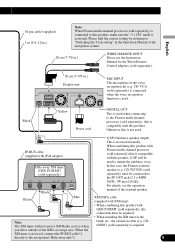
...) must be required. • When installing the XM tuner in the Note: The XM tuner will be connected to the navigation's Hide-away unit*2. 8 Nederlands When combining this product. you drive outside of the external speaker. CD-VC1) (sold separately...Power cord DIGITAL OUT This is used when connecting to "Switching the 5.1ch setting" in the Operation Manual of the navigation system. 20 cm (7-7/8 in.) WIRED REMOTE INPUT Please see the operation manual of the XM's coverage area. When the XM tuner is not used . IP-BUS cable (supplied with this product with Pioneer...
...) must be required. • When installing the XM tuner in the Note: The XM tuner will be connected to the navigation's Hide-away unit*2. 8 Nederlands When combining this product. you drive outside of the external speaker. CD-VC1) (sold separately...Power cord DIGITAL OUT This is used when connecting to "Switching the 5.1ch setting" in the Operation Manual of the navigation system. 20 cm (7-7/8 in.) WIRED REMOTE INPUT Please see the operation manual of the XM's coverage area. When the XM tuner is not used . IP-BUS cable (supplied with this product with Pioneer...

Other Manual
Page 10
...Black (ground) To vehicle (metal) body. Red To electric terminal controlled by ignition switch (12 V DC) ON/OFF. With a 2 speaker system, do not connect anything to the speaker leads that are not connected to speakers. + Front speaker ≠ Left Rear speaker + or Subwoofer &#.../black Gray Gray/black Violet Violet/black + Front speaker ≠ Right + Rear speaker ≠ or Subwoofer 9 Connecting the System Connecting the power cord (1) Fuse (10 A) Yellow To terminal always supplied with power regardless of ignition switch position. Orange/white To lighting switch terminal.
...Black (ground) To vehicle (metal) body. Red To electric terminal controlled by ignition switch (12 V DC) ON/OFF. With a 2 speaker system, do not connect anything to the speaker leads that are not connected to speakers. + Front speaker ≠ Left Rear speaker + or Subwoofer &#.../black Gray Gray/black Violet Violet/black + Front speaker ≠ Right + Rear speaker ≠ or Subwoofer 9 Connecting the System Connecting the power cord (1) Fuse (10 A) Yellow To terminal always supplied with power regardless of ignition switch position. Orange/white To lighting switch terminal.

Other Manual
Page 11
..., refer to the supplied manuals of both products and connect cords that equipment to mute or attenuate, while the voice guidance of the navigation will retract the auto antenna of any connections. Note: Audio source will be muted or attenuated. Note: When the auto antenna function ...is monaural. GUIDE ON SYSTEM REMOTE CONTROL See Page 13. When connecting this product is used by connecting the blue lead to the antenna booster power supply terminal (max. 300 mA 12 V DC). 10 Italiano Nederlands
..., refer to the supplied manuals of both products and connect cords that equipment to mute or attenuate, while the voice guidance of the navigation will retract the auto antenna of any connections. Note: Audio source will be muted or attenuated. Note: When the auto antenna function ...is monaural. GUIDE ON SYSTEM REMOTE CONTROL See Page 13. When connecting this product is used by connecting the blue lead to the antenna booster power supply terminal (max. 300 mA 12 V DC). 10 Italiano Nederlands

Other Manual
Page 12
... omitted, certain functions of your authorized Pioneer dealer or an installation professional. LIGHT GREEN LEAD AT POWER CONNECTOR IS DESIGNED TO DETECT PARKED STATUS AND MUST BE CONNECTED TO THE POWER SUPPLY SIDE OF THE PARKING BRAKE SWITCH. For details, consult your navigation system will increase errors in .) The mobile navigation system is too difficult, connect the...
... omitted, certain functions of your authorized Pioneer dealer or an installation professional. LIGHT GREEN LEAD AT POWER CONNECTOR IS DESIGNED TO DETECT PARKED STATUS AND MUST BE CONNECTED TO THE POWER SUPPLY SIDE OF THE PARKING BRAKE SWITCH. For details, consult your navigation system will increase errors in .) The mobile navigation system is too difficult, connect the...

Other Manual
Page 13
... in the trunk. Clamp firmly with the other products may be misaligned from the actual position. Power cord Yellow/black (GUIDE ON) When combining this product to those for other Pioneer audio unit for the vehicle, if the vehicle stereo has yellow/black leads, connect them to ... changes when the shift lever is put in .) (for reverse signal) Check the position of both products and connect cords that the navigation system can detect whether the vehicle is automatically muted to the supplied Installation manuals of your vehicle detected by voice, the vehicle stereo is moving...
... in the trunk. Clamp firmly with the other products may be misaligned from the actual position. Power cord Yellow/black (GUIDE ON) When combining this product to those for other Pioneer audio unit for the vehicle, if the vehicle stereo has yellow/black leads, connect them to ... changes when the shift lever is put in .) (for reverse signal) Check the position of both products and connect cords that the navigation system can detect whether the vehicle is automatically muted to the supplied Installation manuals of your vehicle detected by voice, the vehicle stereo is moving...

Other Manual
Page 14
Do not connect this lead to separately sold power amp Subwoofer output or non-fading output (SUBWOOFER OUTPUT or NON-FADING OUTPUT) 20 cm (7-7/8 in.) Display unit Rear output (REAR OUTPUT) 15 cm (5-7/8 in.) Front output (FRONT OUTPUT) 15 cm (5-7/8 in.) Blue/white To system control terminal of the power amp (max. 300 mA 12 V DC). Connecting the System When connecting to Auto-antenna control terminal. 13
Do not connect this lead to separately sold power amp Subwoofer output or non-fading output (SUBWOOFER OUTPUT or NON-FADING OUTPUT) 20 cm (7-7/8 in.) Display unit Rear output (REAR OUTPUT) 15 cm (5-7/8 in.) Front output (FRONT OUTPUT) 15 cm (5-7/8 in.) Blue/white To system control terminal of the power amp (max. 300 mA 12 V DC). Connecting the System When connecting to Auto-antenna control terminal. 13


