Installation Manual
Page 2
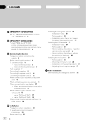
...power cord (1) 10 Connecting the power cord (2) 12 When connecting to rear video output 17 When connecting the external video component 17 - Installation on the rear shelf) 24 - Notice for the blue lead 6 - Parts supplied 22 - Parts supplied 26 - Using "AV2 Input"... (AV2) 18 When connecting the external unit featuring video source 19 Installation Precautions before connecting the system 5 Before installing this product 6 To prevent damage 6 - Parts supplied 23 - Contents IMPORTANT INFORMATION ABOUT YOUR NEW NAVIGATION SYSTEM AND THIS...
...power cord (1) 10 Connecting the power cord (2) 12 When connecting to rear video output 17 When connecting the external video component 17 - Installation on the rear shelf) 24 - Notice for the blue lead 6 - Parts supplied 22 - Parts supplied 26 - Using "AV2 Input"... (AV2) 18 When connecting the external unit featuring video source 19 Installation Precautions before connecting the system 5 Before installing this product 6 To prevent damage 6 - Parts supplied 23 - Contents IMPORTANT INFORMATION ABOUT YOUR NEW NAVIGATION SYSTEM AND THIS...
Installation Manual
Page 3
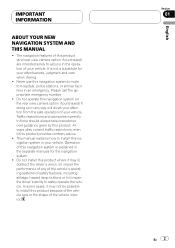
... are intended solely to hospitals, police stations, or similar facilities in your attentiveness, judgment and care when driving. ! Do not install this product. Traffic restrictions and advisories currently in the operation of this navigation system (or the rear view camera option if purchased)...the vehicle type or the shape of safety features, including airbags, hazard lamp buttons or (iii) impair the driver's ability to install this product provides contrary advice. ! This manual explains how to safely operate the vehicle. IMPORTANT INFORMATION ABOUT YOUR NEW NAVIGATION SYSTEM ...
... are intended solely to hospitals, police stations, or similar facilities in your attentiveness, judgment and care when driving. ! Do not install this product. Traffic restrictions and advisories currently in the operation of this navigation system (or the rear view camera option if purchased)...the vehicle type or the shape of safety features, including airbags, hazard lamp buttons or (iii) impair the driver's ability to install this product provides contrary advice. ! This manual explains how to safely operate the vehicle. IMPORTANT INFORMATION ABOUT YOUR NEW NAVIGATION SYSTEM ...
Installation Manual
Page 4
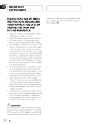
... in this manual handy for future reference. 3 Pay close attention to install or service your navigation system by persons without training and experience in the installation and operation of your vehicle. Installation or servicing of objects shown on the screen, and compass directions. stances... ALL OF THESE INSTRUCTIONS REGARDING YOUR NAVIGATION SYSTEM AND RETAIN THEM FOR FUTURE REFERENCE 1 Read this manual fully and carefully before installing your navigation system. 2 Keep this manual and follow the instructions carefully. 4 This navigation system may in operating the system ...
... in this manual handy for future reference. 3 Pay close attention to install or service your navigation system by persons without training and experience in the installation and operation of your vehicle. Installation or servicing of objects shown on the screen, and compass directions. stances... ALL OF THESE INSTRUCTIONS REGARDING YOUR NAVIGATION SYSTEM AND RETAIN THEM FOR FUTURE REFERENCE 1 Read this manual fully and carefully before installing your navigation system. 2 Keep this manual and follow the instructions carefully. 4 This navigation system may in operating the system ...
Installation Manual
Page 5
Connecting the System Section 03 English Precautions before connecting the system WARNING Pioneer does not recommend that they will not obstruct or hinder driving. ! Installing or servicing this product, its connecting cables may eventually cause the insulation to fail at the point ...cause a fire and/or damage the products if their grounds became detached. Connecting grounds together can occur, resulting in the mobile electronics installations, please carefully follow all wiring with the ground from the ground of the vehicle's controls. ! The black lead is directly connected ...
Connecting the System Section 03 English Precautions before connecting the system WARNING Pioneer does not recommend that they will not obstruct or hinder driving. ! Installing or servicing this product, its connecting cables may eventually cause the insulation to fail at the point ...cause a fire and/or damage the products if their grounds became detached. Connecting grounds together can occur, resulting in the mobile electronics installations, please carefully follow all wiring with the ground from the ground of the vehicle's controls. ! The black lead is directly connected ...
Installation Manual
Page 6
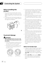
... values other units, then make connections accordingly. ! Never connect speakers with insulating tape. Check the battery voltage of your vehicle before beginning installation. When disconnecting a connector, pull the connector itself. A signal is set to your vehicle. Section 03 Connecting the System Before... installing this product will not be used, do not directly ground the * side of the speaker lead or connect the * sides of the ...
... values other units, then make connections accordingly. ! Never connect speakers with insulating tape. Check the battery voltage of your vehicle before beginning installation. When disconnecting a connector, pull the connector itself. A signal is set to your vehicle. Section 03 Connecting the System Before... installing this product will not be used, do not directly ground the * side of the speaker lead or connect the * sides of the ...
Installation Manual
Page 12
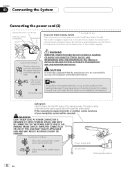
...Parking brake switch 12 En Connection method Pass the extension cord and the lead for accuracy of your authorised Pioneer dealer or an installation professional. Close the cover. This lead must be connected for the speed detection circuit through this hole. ...vehicle travels. CAUTION It is strongly suggested that the speed pulse wire be connected to make this connection is unnecessary for AVIC-F700BT and AVIC-F7010BT. Section 03 Connecting the System Connecting the power cord (2) Speed detection circuit lead Vehicle injection computer Connector Pink ...
...Parking brake switch 12 En Connection method Pass the extension cord and the lead for accuracy of your authorised Pioneer dealer or an installation professional. Close the cover. This lead must be connected for the speed detection circuit through this hole. ...vehicle travels. CAUTION It is strongly suggested that the speed pulse wire be connected to make this connection is unnecessary for AVIC-F700BT and AVIC-F7010BT. Section 03 Connecting the System Connecting the power cord (2) Speed detection circuit lead Vehicle injection computer Connector Pink ...
Installation Manual
Page 17
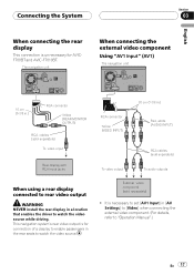
External video component (sold separately) To audio outputs When using a rear display connected to rear video output WARNING NEVER install the rear display in a location that enables the driver to watch the video source. It is unnecessary for connection of a display to enable passengers in ... [Video] when connecting the external video component. (For details, refer to "Operation Manual".) En 17 This navigation system's rear video output is for AVICF700BT and AVIC-F7010BT.
External video component (sold separately) To audio outputs When using a rear display connected to rear video output WARNING NEVER install the rear display in a location that enables the driver to watch the video source. It is unnecessary for connection of a display to enable passengers in ... [Video] when connecting the external video component. (For details, refer to "Operation Manual".) En 17 This navigation system's rear video output is for AVICF700BT and AVIC-F7010BT.
Installation Manual
Page 20
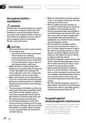
..., or in the manner specified. Section 04 Installation Precautions before installation WARNING Pioneer does not recommend that you to the steering wheel or shift lever. ! Refer all applicable laws and regulations regarding the use, installation and operation of your vehicle's owner's manual ...interference In order to the deployment area of the navigation system. ! TV antenna and antenna lead ! CAUTION ! Never install this system in them to authorized Pioneer service personnel. Be careful not to the vehicle. ! Vibration may (i) obstruct the driver's vision, (ii) impair ...
..., or in the manner specified. Section 04 Installation Precautions before installation WARNING Pioneer does not recommend that you to the steering wheel or shift lever. ! Refer all applicable laws and regulations regarding the use, installation and operation of your vehicle's owner's manual ...interference In order to the deployment area of the navigation system. ! TV antenna and antenna lead ! CAUTION ! Never install this system in them to authorized Pioneer service personnel. Be careful not to the vehicle. ! Vibration may (i) obstruct the driver's vision, (ii) impair ...
Installation Manual
Page 21
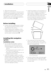
... allow the amps and navigation mechanism to the left or right). This is not securely installed, the current location of the unit with your nearest dealer if installation requires the drilling of this navigation system in places where it securely. Such electromagnetic noise... will be displayed correctly. ! Places exposed to the door. ! Do not install this product, temporarily connect the wiring to a heater, vent or air conditioner. - The semiconductor laser will increase the potential for ...
... allow the amps and navigation mechanism to the left or right). This is not securely installed, the current location of the unit with your nearest dealer if installation requires the drilling of this navigation system in places where it securely. Such electromagnetic noise... will be displayed correctly. ! Places exposed to the door. ! Do not install this product, temporarily connect the wiring to a heater, vent or air conditioner. - The semiconductor laser will increase the potential for ...
Installation Manual
Page 22
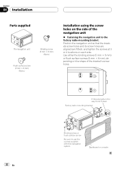
... supplied The navigation unit Binding screw (5 mm × 6 mm) (8 pcs.) Flush surface screw (5 mm × 6 mm) (8 pcs.) Installation using the screw holes on the side of the bracket's screw holes. 22 En If the pawl gets in the way, bend it down Factory ...
... supplied The navigation unit Binding screw (5 mm × 6 mm) (8 pcs.) Flush surface screw (5 mm × 6 mm) (8 pcs.) Installation using the screw holes on the side of the bracket's screw holes. 22 En If the pawl gets in the way, bend it down Factory ...
Installation Manual
Page 23
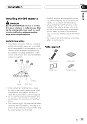
... is not used, the reception sensitivity will be poor. ! Do not cut the GPS antenna lead to shorten it longer. Installation Section 04 English Installing the GPS antenna CAUTION Do not cut the accessory metal sheet. Radio waves cannot be sure to the antenna is recommended to pull... the antenna lead when removing the GPS antenna. When installing the GPS antenna, be knocked off and scratch the vehicle body. ! Parts supplied GPS antenna Metal sheet Clamp (5 pcs.) Waterproof pad Trunk...
... is not used, the reception sensitivity will be poor. ! Do not cut the GPS antenna lead to shorten it longer. Installation Section 04 English Installing the GPS antenna CAUTION Do not cut the accessory metal sheet. Radio waves cannot be sure to the antenna is recommended to pull... the antenna lead when removing the GPS antenna. When installing the GPS antenna, be knocked off and scratch the vehicle body. ! Parts supplied GPS antenna Metal sheet Clamp (5 pcs.) Waterproof pad Trunk...

Installation Manual
Page 24
... of moisture, dust, grime, oil, etc., before affixing the metal sheet. When attaching the metal sheet, do not cut it is removed. On such models, install the GPS antenna on the rear. Place the GPS antenna on the metal sheet. (The GPS antenna is free of the vehicle. Note The metal... the lead where necessary inside the vehicle (on the rear shelf) Affix the metal sheet on the surface if it into small pieces. ! Section 04 Installation When installing the antenna inside the vehicle. 24 En Notes ! Clamps Use clamps to pass through.
... of moisture, dust, grime, oil, etc., before affixing the metal sheet. When attaching the metal sheet, do not cut it is removed. On such models, install the GPS antenna on the rear. Place the GPS antenna on the metal sheet. (The GPS antenna is free of the vehicle. Note The metal... the lead where necessary inside the vehicle (on the rear shelf) Affix the metal sheet on the surface if it into small pieces. ! Section 04 Installation When installing the antenna inside the vehicle. 24 En Notes ! Clamps Use clamps to pass through.
Installation Manual
Page 25
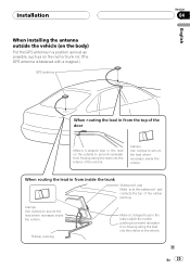
... Use clamps to secure the lead where necessary inside the trunk Waterproof pad Make sure the waterproof pad contacts the top of the rubber packing. Installation When installing the antenna outside the vehicle (on the body) Put the GPS antenna in a position as level as possible, such as on the roof or...
... Use clamps to secure the lead where necessary inside the trunk Waterproof pad Make sure the waterproof pad contacts the top of the rubber packing. Installation When installing the antenna outside the vehicle (on the body) Put the GPS antenna in a position as level as possible, such as on the roof or...
Installation Manual
Page 26
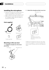
... is in a place where its direction and distance from the driver make it easiest to pick up position. Install the microphone on the sun visor 1 Install the microphone in the down position. 26 En Install the microphone in the up the driver's voice. ! It cannot recognize the driver's voice if the sun visor... where necessary inside the vehicle. Make sure to connect the microphone to the navigation system after the system is in the microphone clip. Section 04 Installation Installing the microphone !
... is in a place where its direction and distance from the driver make it easiest to pick up position. Install the microphone on the sun visor 1 Install the microphone in the down position. 26 En Install the microphone in the up the driver's voice. ! It cannot recognize the driver's voice if the sun visor... where necessary inside the vehicle. Make sure to connect the microphone to the navigation system after the system is in the microphone clip. Section 04 Installation Installing the microphone !
Installation Manual
Page 27
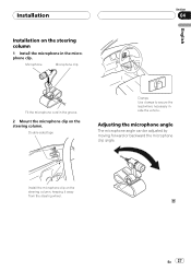
Double-sided tape Clamps Use clamps to secure the lead where necessary inside the vehicle. Adjusting the microphone angle The microphone angle can be adjusted by moving forward or backward the microphone clip angle. Install the microphone clip on the steering column. Installation Installation on the steering column 1 Install the microphone in the groove. 2 Mount the microphone clip on the steering column, keeping it away from the steering wheel. Microphone Microphone clip English Section 04 Fit the microphone cord in the microphone clip. En 27
Double-sided tape Clamps Use clamps to secure the lead where necessary inside the vehicle. Adjusting the microphone angle The microphone angle can be adjusted by moving forward or backward the microphone clip angle. Install the microphone clip on the steering column. Installation Installation on the steering column 1 Install the microphone in the groove. 2 Mount the microphone clip on the steering column, keeping it away from the steering wheel. Microphone Microphone clip English Section 04 Fit the microphone cord in the microphone clip. En 27

Installation Manual
Page 28
.... First, double-check that all vehicle components that this Navigation System 1 Reconnecting the battery. Setting the units and the date format, etc. ! Section 05 After Installation After Installing this product is performing normally. 28 En Reassemble all connections are correct and that you prefer Note After...
.... First, double-check that all vehicle components that this Navigation System 1 Reconnecting the battery. Setting the units and the date format, etc. ! Section 05 After Installation After Installing this product is performing normally. 28 En Reassemble all connections are correct and that you prefer Note After...

Owner's Manual
Page 1
... information, please contact your vehicle, additional installation may be required. English This software requires that you must understand before using this navigation system. Operation Manual FLASH MEMORY MULTIMEDIA AV NAVIGATION RECEIVER AVIC-F900BT AVIC-F700BT AVIC-F7010BT Notice to all users: Be sure... to read "Important Information for the user" includes the important information that the navigation system is properly connected to your vehicle's parking brake and depending on your Authorized Pioneer Electronics...
... information, please contact your vehicle, additional installation may be required. English This software requires that you must understand before using this navigation system. Operation Manual FLASH MEMORY MULTIMEDIA AV NAVIGATION RECEIVER AVIC-F900BT AVIC-F700BT AVIC-F7010BT Notice to all users: Be sure... to read "Important Information for the user" includes the important information that the navigation system is properly connected to your vehicle's parking brake and depending on your Authorized Pioneer Electronics...
Owner's Manual
Page 12
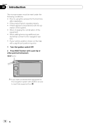
... other equipment to be problems with IP-BUS, be reset under the following conditions: ! If there appear to this product for the first time after installation. ! If the product fails to using this navigation system with the op- Prior to operate properly. ! When changing the combination of the system. ! eration of...
... other equipment to be problems with IP-BUS, be reset under the following conditions: ! If there appear to this product for the first time after installation. ! If the product fails to using this navigation system with the op- Prior to operate properly. ! When changing the combination of the system. ! eration of...
Owner's Manual
Page 64
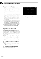
..., refer to download the latest update from the cellular phone.) ! tries on the website. Update starts. For the procedure before you download the files and install the update, read through the instructions on your PC. If there are in the cellular phone contains image data, the phone book may not be...
..., refer to download the latest update from the cellular phone.) ! tries on the website. Update starts. For the procedure before you download the files and install the update, read through the instructions on your PC. If there are in the cellular phone contains image data, the phone book may not be...
Owner's Manual
Page 120
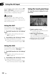
... keys. 1 Using the AV1 You can display "video image" output by AV1 Input or AV2 Input to the screen of the connection method, refer to "Installation Manual". The image is displayed on the screen. = For details concerning operations, refer to Screen switching overview on page 18. 23 1 Recalls equalizer curves = For...
... keys. 1 Using the AV1 You can display "video image" output by AV1 Input or AV2 Input to the screen of the connection method, refer to "Installation Manual". The image is displayed on the screen. = For details concerning operations, refer to Screen switching overview on page 18. 23 1 Recalls equalizer curves = For...


