Installation Manual
Page 2
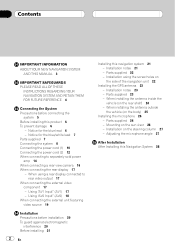
...amp 14 When connecting a rear view camera 16 When connecting the rear display 17 - When installing the antenna outside the vehicle (on the side of the navigation unit 22 Installing the GPS antenna 23 - Notice for the blue lead 6 - Mounting on the rear shelf) 24 - Notice for the...video component 17 - When using the screw holes on the body) 25 Installing the microphone 26 - Installation notes 21 - When installing the antenna inside the vehicle (on the sun visor 26 - Installation on the steering column 27 - Contents IMPORTANT INFORMATION ABOUT YOUR NEW NAVIGATION SYSTEM ...
...amp 14 When connecting a rear view camera 16 When connecting the rear display 17 - When installing the antenna outside the vehicle (on the side of the navigation unit 22 Installing the GPS antenna 23 - Notice for the blue lead 6 - Mounting on the rear shelf) 24 - Notice for the...video component 17 - When using the screw holes on the body) 25 Installing the microphone 26 - Installation notes 21 - When installing the antenna inside the vehicle (on the sun visor 26 - Installation on the steering column 27 - Contents IMPORTANT INFORMATION ABOUT YOUR NEW NAVIGATION SYSTEM ...
Installation Manual
Page 5
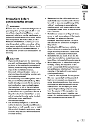
...a result of the lead will be exceeded, causing overheating. ! Do not cut the GPS antenna cable to shorten it or use an extension to remain exposed. ! Altering the antenna cable could result in the mobile electronics installations, please carefully follow all wiring with metal parts...Connecting grounds together can occur, resulting in the installation manual. ! Connecting the System Section 03 English Precautions before connecting the system WARNING Pioneer does not recommend that you do, the protection circuit (fuse holder, fuse resistor or filter, etc.) may fail to work properly....
...a result of the lead will be exceeded, causing overheating. ! Do not cut the GPS antenna cable to shorten it or use an extension to remain exposed. ! Altering the antenna cable could result in the mobile electronics installations, please carefully follow all wiring with metal parts...Connecting grounds together can occur, resulting in the installation manual. ! Connecting the System Section 03 English Precautions before connecting the system WARNING Pioneer does not recommend that you do, the protection circuit (fuse holder, fuse resistor or filter, etc.) may fail to work properly....

Installation Manual
Page 7
...Be sure not to [Power], the vehicle's antenna can be stowed or turned off only when the ignition switch is set to use this lead as the power supply lead for the external power amps. Notice for speed signal) GPS antenna RCA connector Microphone En 7 Do not connect ...this lead as the power supply lead for the auto-antenna or antenna booster. Parts supplied Parts marked (*) are not supplied with AVICF700BT and AVIC-F7010BT. Connecting the System Section 03 English -...
...Be sure not to [Power], the vehicle's antenna can be stowed or turned off only when the ignition switch is set to use this lead as the power supply lead for the external power amps. Notice for speed signal) GPS antenna RCA connector Microphone En 7 Do not connect ...this lead as the power supply lead for the auto-antenna or antenna booster. Parts supplied Parts marked (*) are not supplied with AVICF700BT and AVIC-F7010BT. Connecting the System Section 03 English -...
Installation Manual
Page 9
... The XM tuner, HD-Radio tuner and SIRIUS satellite radio tuner will not receive their coverage area. En 9 Connecting the System Section 03 English Microphone GPS antenna DIGITAL OUT This terminal is intended to support future equipment and should not be used while the vehicle is a visible distraction to "Operation Manual". WARNING...
... The XM tuner, HD-Radio tuner and SIRIUS satellite radio tuner will not receive their coverage area. En 9 Connecting the System Section 03 English Microphone GPS antenna DIGITAL OUT This terminal is intended to support future equipment and should not be used while the vehicle is a visible distraction to "Operation Manual". WARNING...
Installation Manual
Page 21
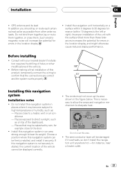
...'t install the navigation unit anywhere hot -for errors in an area strong enough to bear its lead In addition you should lay or route each antenna lead as far as on a surface within 0 degrees to 30 degrees tolerance (within 10 degrees to high temperatures or humidity, such as: - ...errors in places where it may become subject to the left or right). Places that the connections are correct and the system works properly. GPS antenna and its weight. Do not install this navigation system in the location display, and might otherwise cause reduced display performance. Do not cover ...
...'t install the navigation unit anywhere hot -for errors in an area strong enough to bear its lead In addition you should lay or route each antenna lead as far as on a surface within 0 degrees to 30 degrees tolerance (within 10 degrees to high temperatures or humidity, such as: - ...errors in places where it may become subject to the left or right). Places that the connections are correct and the system works properly. GPS antenna and its weight. Do not install this navigation system in the location display, and might otherwise cause reduced display performance. Do not cover ...
Installation Manual
Page 23
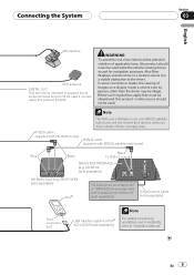
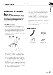
... radio waves will be poor. ! When installing the GPS antenna, be blocked as little as this is blocked. When installing the GPS antenna on the outside of the GPS antenna. ! Do not paint the GPS antenna, as possible. Parts supplied GPS antenna Metal sheet Clamp (5 pcs.) Waterproof pad Trunk lid Roof... the vehicle, always put it in a short circuit or malfunction and permanent damage to pull the antenna lead when removing the GPS antenna. Altering the antenna cable could result in the vehicle when going through an automatic vehicle wash. Radio waves cannot be ...
... radio waves will be poor. ! When installing the GPS antenna, be blocked as little as this is blocked. When installing the GPS antenna on the outside of the GPS antenna. ! Do not paint the GPS antenna, as possible. Parts supplied GPS antenna Metal sheet Clamp (5 pcs.) Waterproof pad Trunk lid Roof... the vehicle, always put it in a short circuit or malfunction and permanent damage to pull the antenna lead when removing the GPS antenna. Altering the antenna cable could result in the vehicle when going through an automatic vehicle wash. Radio waves cannot be ...

Installation Manual
Page 24
... the rear shelf) Affix the metal sheet on as level a surface as possible where the GPS antenna faces the window. Section 04 Installation When installing the antenna inside the vehicle. 24 En Place the GPS antenna on the surface if it into small pieces. ! Notes ! Note The metal sheet contains ...a strong adhesive which may leave a mark on the metal sheet. (The GPS antenna is free of the vehicle. Make sure the surface is fastened with its magnet.) GPS antenna Metal Sheet Peel off the protective sheet on the outside of moisture, dust, grime, oil, etc., ...
... the rear shelf) Affix the metal sheet on as level a surface as possible where the GPS antenna faces the window. Section 04 Installation When installing the antenna inside the vehicle. 24 En Place the GPS antenna on the surface if it into small pieces. ! Notes ! Note The metal sheet contains ...a strong adhesive which may leave a mark on the metal sheet. (The GPS antenna is free of the vehicle. Make sure the surface is fastened with its magnet.) GPS antenna Metal Sheet Peel off the protective sheet on the outside of moisture, dust, grime, oil, etc., ...
Installation Manual
Page 25
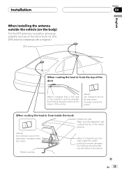
... the lead where necessary inside the vehicle. Installation When installing the antenna outside the vehicle (on the body) Put the GPS antenna in a position as level as possible, such as on the roof or trunk lid. (The GPS antenna is fastened with a magnet.) GPS antenna English Section 04 When routing the lead in from the top of...
... the lead where necessary inside the vehicle. Installation When installing the antenna outside the vehicle (on the body) Put the GPS antenna in a position as level as possible, such as on the roof or trunk lid. (The GPS antenna is fastened with a magnet.) GPS antenna English Section 04 When routing the lead in from the top of...

Owner's Manual
Page 6
...- Setting the illumination color 137 - Enhancing bass (Bass Booster) 142 The options on the "System Settings" menu 135 - Switching the auto antenna setting 143 - Switching the sound muting/ attenuation 144 - Contents - Overview Mode 127 - Setting the rear view camera 136 - Turning off ...iPod music information 145 Using the "Instant Replay" function 117 Using the "Function" menu 117 - Basic operations in the "Navi Settings" menu 123 - GPS & Time Settings 123 - Time Settings 124 - 3D Settings 125 - Map Settings 125 - Set Home 129 - About 130 6 En - Using balance...
...- Setting the illumination color 137 - Enhancing bass (Bass Booster) 142 The options on the "System Settings" menu 135 - Switching the auto antenna setting 143 - Switching the sound muting/ attenuation 144 - Contents - Overview Mode 127 - Setting the rear view camera 136 - Turning off ...iPod music information 145 Using the "Instant Replay" function 117 Using the "Function" menu 117 - Basic operations in the "Navi Settings" menu 123 - GPS & Time Settings 123 - Time Settings 124 - 3D Settings 125 - Map Settings 125 - Set Home 129 - About 130 6 En - Using balance...

Owner's Manual
Page 123
...the "Navi Settings" menu Basic operations in detail. 3 On-off control Touching [On] or [Off] enables activation or deactivation of the GPS antenna, its reception sensitivity, and from how many satellites the signal is described here, along with an operational example. 1 Press MENU button to... the preferences in the "Navi Settings" menu Preferences related to display the "Top Menu", and then touch [Settings]. 2 Touch [Navi Settings]. GPS & Time Settings Indicates the connection status of this function. 5 Touch to return to change the settings. 1 23 1 Slider Touching the desired ...
...the "Navi Settings" menu Basic operations in detail. 3 On-off control Touching [On] or [Off] enables activation or deactivation of the GPS antenna, its reception sensitivity, and from how many satellites the signal is described here, along with an operational example. 1 Press MENU button to... the preferences in the "Navi Settings" menu Preferences related to display the "Top Menu", and then touch [Settings]. 2 Touch [Navi Settings]. GPS & Time Settings Indicates the connection status of this function. 5 Touch to return to change the settings. 1 23 1 Slider Touching the desired ...
Owner's Manual
Page 124
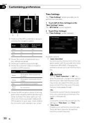
...may not be calculated if the time you to set does not match the time zone of GPS antenna. In such case, check whether the connection and installation are correct. The "GPS Status" screen appears. 2 Touch [Time Settings]. Color Green Yellow Red Black with the ...there is works normally. The "Time Settings" screen appears. Available options; ! A blinking green lamp indicates whether positioning is a problem related with GPS reception. Note that your route passes through. [On]: Corrects the current time by changing the time zone automatically according to this system's whereabouts....
...may not be calculated if the time you to set does not match the time zone of GPS antenna. In such case, check whether the connection and installation are correct. The "GPS Status" screen appears. 2 Touch [Time Settings]. Color Green Yellow Red Black with the ...there is works normally. The "Time Settings" screen appears. Available options; ! A blinking green lamp indicates whether positioning is a problem related with GPS reception. Note that your route passes through. [On]: Corrects the current time by changing the time zone automatically according to this system's whereabouts....
Owner's Manual
Page 156
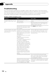
... accuracy. lowing reasons: • The GPS antenna is blown. Do not cover the GPS antenna with spray paint or vehicle wax, because this section. The most common problems. If a solution to reduce accu- navigation system doesn't oper- The fuse is in microprocessor to distort positioning data for AVIC-F900BT and AVIC-F90BT.) Check that all connections are...
... accuracy. lowing reasons: • The GPS antenna is blown. Do not cover the GPS antenna with spray paint or vehicle wax, because this section. The most common problems. If a solution to reduce accu- navigation system doesn't oper- The fuse is in microprocessor to distort positioning data for AVIC-F900BT and AVIC-F90BT.) Check that all connections are...
Owner's Manual
Page 166
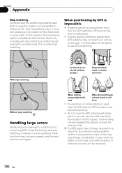
... considerably or may not reach your position by this may block the reception of GPS signals. If signals cannot be received from GPS satellites may not be updated. Do not cover the GPS antenna with spray paint or car wax, because this navigation system are kept to use...En If a car phone or cellular phone is called map matching. Appendix Appendix Map matching As mentioned, the positioning systems used near the GPS antenna, GPS reception may be lost temporarily. ! In this case, it to certain errors. With map matching In tunnels or enclosed parking garages Under...
... considerably or may not reach your position by this may block the reception of GPS signals. If signals cannot be received from GPS satellites may not be updated. Do not cover the GPS antenna with spray paint or car wax, because this navigation system are kept to use...En If a car phone or cellular phone is called map matching. Appendix Appendix Map matching As mentioned, the positioning systems used near the GPS antenna, GPS reception may be lost temporarily. ! In this case, it to certain errors. With map matching In tunnels or enclosed parking garages Under...
Owner's Manual
Page 190
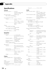
... 15.1 V DC) Grounding system Negative type Max. once per second GPS antenna: Antenna Micro strip flat antenna/ right-handed helical polarisation Antenna cable 5.0 m (16 ft. 5 in.) Dimensions (W × H × D 33 mm × 15 mm × 36 mm (1-1/4 in. × 5/8 in. × 1-3/8 in .) Weight: AVIC-F900BT, AVIC-F90BT 2.2 kg (4.9 lbs) AVIC-F700BT, AVIC-F7010BT 2.1 kg (4.6 lbs) NAND flash memory 2 GB Navigation...
... 15.1 V DC) Grounding system Negative type Max. once per second GPS antenna: Antenna Micro strip flat antenna/ right-handed helical polarisation Antenna cable 5.0 m (16 ft. 5 in.) Dimensions (W × H × D 33 mm × 15 mm × 36 mm (1-1/4 in. × 5/8 in. × 1-3/8 in .) Weight: AVIC-F900BT, AVIC-F90BT 2.2 kg (4.9 lbs) AVIC-F700BT, AVIC-F7010BT 2.1 kg (4.6 lbs) NAND flash memory 2 GB Navigation...


