Installation Manual
Page 3
... 01 En 3 English Always obey current traffic restrictions, even if this product. Operation of this navigation system (or the rear view camera option if purchased) if doing so in the separate manuals for your vehicle. Do not operate this navigation system is not a substitute for the navigation system. ! Do not install this product where it may (i) obstruct the driver...
... 01 En 3 English Always obey current traffic restrictions, even if this product. Operation of this navigation system (or the rear view camera option if purchased) if doing so in the separate manuals for your vehicle. Do not operate this navigation system is not a substitute for the navigation system. ! Do not install this product where it may (i) obstruct the driver...
Installation Manual
Page 4
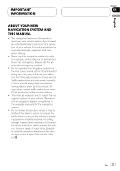
..., and compass directions. Please comply with any accessory in your vehicle's interior, the navigation system should not divert your attention from the safe operation of your navigation system by persons without training and experience in electronic equipment and 4 En If you to... YOUR NAVIGATION SYSTEM AND RETAIN THEM FOR FUTURE REFERENCE 1 Read this manual fully and carefully before installing your navigation system. 2 Keep this manual handy for future reference. 3 Pay close attention to all warnings in this manual and follow the instructions carefully. 4 This navigation system may ...
..., and compass directions. Please comply with any accessory in your vehicle's interior, the navigation system should not divert your attention from the safe operation of your navigation system by persons without training and experience in electronic equipment and 4 En If you to... YOUR NAVIGATION SYSTEM AND RETAIN THEM FOR FUTURE REFERENCE 1 Read this manual fully and carefully before installing your navigation system. 2 Keep this manual handy for future reference. 3 Pay close attention to all warnings in this manual and follow the instructions carefully. 4 This navigation system may ...
Installation Manual
Page 6
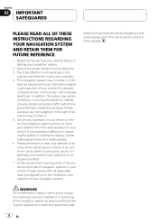
... To avoid shorts in the electrical system, be sure to disconnect the (-) battery cable before installation. ! F ACC O F O OF OF N STAR N STAR T T ACC position No ACC position ! Since a unique BPTL circuit is employed, do not remove the caps attached to "Operation Manual".) ! Connecting speakers with a 12...of the speaker lead or connect the * sides of the rating prescribed on this navigation system. ! Be sure to connect the * side of the speaker lead to control the antenna of your navigation system. It is output through the blue lead to the * side of the connector...
... To avoid shorts in the electrical system, be sure to disconnect the (-) battery cable before installation. ! F ACC O F O OF OF N STAR N STAR T T ACC position No ACC position ! Since a unique BPTL circuit is employed, do not remove the caps attached to "Operation Manual".) ! Connecting speakers with a 12...of the speaker lead or connect the * sides of the rating prescribed on this navigation system. ! Be sure to connect the * side of the speaker lead to control the antenna of your navigation system. It is output through the blue lead to the * side of the connector...
Installation Manual
Page 8
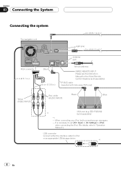
Section 03 Connecting the System Connecting the system The navigation unit 4 m (13 ft. 1 in.) Light gray 5 m (16 ft. 5 in.) RCA connector 2 m (6 ft. 7 in.) Blue 20 cm (7-7/8 in [AV Settings] to [iPod] when connecting the iPod. (For details, refer to "Operation Manual".) USB connector Connect either the interface cable for the Wired Remote Control Adapters (...tuner (e.g. GEX-P920XM) *1 (sold separately). It is necessary to set [AV1 Input] in .) Antenna jack Vehicle antenna WIRED REMOTE INPUT Please see the Instruction Manual for iPod or an appropriate USB storage device. *1 8 En
Section 03 Connecting the System Connecting the system The navigation unit 4 m (13 ft. 1 in.) Light gray 5 m (16 ft. 5 in.) RCA connector 2 m (6 ft. 7 in.) Blue 20 cm (7-7/8 in [AV Settings] to [iPod] when connecting the iPod. (For details, refer to "Operation Manual".) USB connector Connect either the interface cable for the Wired Remote Control Adapters (...tuner (e.g. GEX-P920XM) *1 (sold separately). It is necessary to set [AV1 Input] in .) Antenna jack Vehicle antenna WIRED REMOTE INPUT Please see the Instruction Manual for iPod or an appropriate USB storage device. *1 8 En
Installation Manual
Page 9
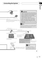
... IP-BUS cable (supplied with SiriusConnect vehicle kit" (sold separately) SiriusConnect Cable (sold separately) Dock connector port USB Interface Cable for navigation purposes. GEX-P10HD) (sold separately) iPod® "SiriusConnect universal tuner" or "SIRIUS Dock and play radio with SIRIUS satellite radio...compatiblity, refer to "Operation Manual". Note The XM tuner, HD-Radio tuner and SIRIUS satellite radio tuner will not receive their service when you are using this product by persons other than the driver may be illegal. Connecting the System Section 03 English ...
... IP-BUS cable (supplied with SiriusConnect vehicle kit" (sold separately) SiriusConnect Cable (sold separately) Dock connector port USB Interface Cable for navigation purposes. GEX-P10HD) (sold separately) iPod® "SiriusConnect universal tuner" or "SIRIUS Dock and play radio with SIRIUS satellite radio...compatiblity, refer to "Operation Manual". Note The XM tuner, HD-Radio tuner and SIRIUS satellite radio tuner will not receive their service when you are using this product by persons other than the driver may be illegal. Connecting the System Section 03 English ...

Installation Manual
Page 10
Front speaker Left Rear speaker or Subwoofer (4 Ω) White White/Black Green Green/Black With a 2 speaker system, do not connect anything with green and green/black leads. Green Green/Black Violet Violet/Black Subwoofer (4 Ω) 2 10 En...(1) Yellow To terminal always supplied with violet and violet/black leads of this navigation system is connected to this navigation system instead of a rear speaker, change the rear output setting in the Initial Setting. (Refer to "Operation Manual".) The subwoofer output of ignition switch position. Do not connect anything to the...
Front speaker Left Rear speaker or Subwoofer (4 Ω) White White/Black Green Green/Black With a 2 speaker system, do not connect anything with green and green/black leads. Green Green/Black Violet Violet/Black Subwoofer (4 Ω) 2 10 En...(1) Yellow To terminal always supplied with violet and violet/black leads of this navigation system is connected to this navigation system instead of a rear speaker, change the rear output setting in the Initial Setting. (Refer to "Operation Manual".) The subwoofer output of ignition switch position. Do not connect anything to the...
Installation Manual
Page 11
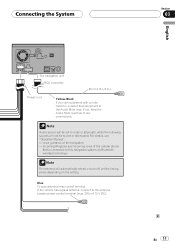
... incoming voice of the cellular phone that equipment to the antenna booster power control terminal (max. 300 mA 12 V DC). Connecting the System Section 03 English The navigation unit RCA connector 26 cm (10-1/4 in.) Power cord Yellow/Black If you use equipment with a mute function, connect that is connected... sounds will automatically retract or turn off, yet the timing varies depending on the setting. Note Audio source will be set to this navigation system via Bluetooth wireless technology Note The antenna will not be muted or attenuated. For details, see "Operation Manual". -
... incoming voice of the cellular phone that equipment to the antenna booster power control terminal (max. 300 mA 12 V DC). Connecting the System Section 03 English The navigation unit RCA connector 26 cm (10-1/4 in.) Power cord Yellow/Black If you use equipment with a mute function, connect that is connected... sounds will automatically retract or turn off, yet the timing varies depending on the setting. Note Audio source will be set to this navigation system via Bluetooth wireless technology Note The antenna will not be muted or attenuated. For details, see "Operation Manual". -
Installation Manual
Page 14
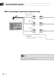
Section 03 Connecting the System When connecting to separately sold power amp Subwoofer output (SUBWOOFER OUTPUT) 28cm (11 in.) RCA connector Rear output (REAR OUTPUT) 30cm (11-7/8 in.) The navigation unit Front output (FRONT OUTPUT) 30cm (11-7/8 in.) 30cm (11-7/8 in.) Blue/white To system control terminal of the power amp (max. 300 mA 12 V DC). 14 En Note You can change the RCA output of the subwoofer depending on your subwoofer system. (Refer to "Operation Manual".)
Section 03 Connecting the System When connecting to separately sold power amp Subwoofer output (SUBWOOFER OUTPUT) 28cm (11 in.) RCA connector Rear output (REAR OUTPUT) 30cm (11-7/8 in.) The navigation unit Front output (FRONT OUTPUT) 30cm (11-7/8 in.) 30cm (11-7/8 in.) Blue/white To system control terminal of the power amp (max. 300 mA 12 V DC). 14 En Note You can change the RCA output of the subwoofer depending on your subwoofer system. (Refer to "Operation Manual".)

Installation Manual
Page 16
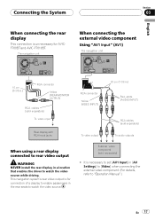
... details about the wiring, refer to "Operation Manual".) ! Do not use only the supplied extension lead. Do not connect to the rear view camera. RearView mode also allows you to use this navigation system. 5 m (16 ft. 5 in.) The navigation unit Extension lead (for entertainment purposes. ...! The object in [System Settings] to [On] when connecting the rear view camera. (For details, refer to...
... details about the wiring, refer to "Operation Manual".) ! Do not use only the supplied extension lead. Do not connect to the rear view camera. RearView mode also allows you to use this navigation system. 5 m (16 ft. 5 in.) The navigation unit Extension lead (for entertainment purposes. ...! The object in [System Settings] to [On] when connecting the rear view camera. (For details, refer to...
Installation Manual
Page 17
... When connecting the external video component Using "AV1 Input" (AV1) The navigation unit 15 cm (5-7/8 in.) RCA connector Yellow (REAR MONITOR OUTPUT) RCA cables (sold separately) To video input RCA connector Yellow (VIDEO INPUT) Rear ...that enables the driver to "Operation Manual".) En 17 It is necessary to set [AV1 Input] in [AV Settings] to [Video] when connecting the external video component. (For details, refer to watch the video source. This navigation system's rear video output is for AVICF700BT and AVIC-F7010BT. Connecting the System Section 03 English When connecting...
... When connecting the external video component Using "AV1 Input" (AV1) The navigation unit 15 cm (5-7/8 in.) RCA connector Yellow (REAR MONITOR OUTPUT) RCA cables (sold separately) To video input RCA connector Yellow (VIDEO INPUT) Rear ...that enables the driver to "Operation Manual".) En 17 It is necessary to set [AV1 Input] in [AV Settings] to [Video] when connecting the external video component. (For details, refer to watch the video source. This navigation system's rear video output is for AVICF700BT and AVIC-F7010BT. Connecting the System Section 03 English When connecting...
Installation Manual
Page 18
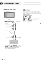
... L RG V L : Left audio (White) R : Right audio (Red) V : Video (Yellow) G : Ground To video output To audio outputs External video component (sold separately) ! Section 03 Connecting the System Using "AV2 Input" (AV2) The navigation unit Mini jack CD-RM10 (sold separately) Yellow RCA cables (sold separately) Red, white CAUTION Be sure to "Operation Manual".) 18 En
... L RG V L : Left audio (White) R : Right audio (Red) V : Video (Yellow) G : Ground To video output To audio outputs External video component (sold separately) ! Section 03 Connecting the System Using "AV2 Input" (AV2) The navigation unit Mini jack CD-RM10 (sold separately) Yellow RCA cables (sold separately) Red, white CAUTION Be sure to "Operation Manual".) 18 En
Installation Manual
Page 19
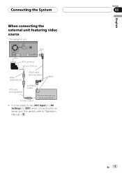
It is necessary to "Operation Manual".) English Section 03 En 19 Connecting the System When connecting the external unit featuring video source The navigation unit Blue RCA connector 20 cm (7-7/8 in [AV Settings] to [EXT] when connecting the external unit. (For details, refer to set [AV1 Input] in .) Yellow (VIDEO INPUT) IP-BUS cable (sold separately) Black RCA cable (sold separately) To IP-BUS output To video output Pioneer external unit (sold separately) !
It is necessary to "Operation Manual".) English Section 03 En 19 Connecting the System When connecting the external unit featuring video source The navigation unit Blue RCA connector 20 cm (7-7/8 in [AV Settings] to [EXT] when connecting the external unit. (For details, refer to set [AV1 Input] in .) Yellow (VIDEO INPUT) IP-BUS cable (sold separately) Black RCA cable (sold separately) To IP-BUS output To video output Pioneer external unit (sold separately) !
Installation Manual
Page 20
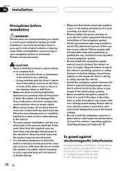
.... Please refer to the deployment area of your vehicle's owner's manual for reference to your navigation system. ! TV antenna and antenna lead ! Refer all applicable laws and regulations regarding the use, installation and operation of the frontal airbags. ! tion of the vehicle, such as... government laws may prohibit or restrict the placement and use the supplied parts in front of the navigation system. ! Section 04 Installation Precautions before installation WARNING Pioneer does not recommend that they may work loose and the product may become wound around the steering ...
.... Please refer to the deployment area of your vehicle's owner's manual for reference to your navigation system. ! TV antenna and antenna lead ! Refer all applicable laws and regulations regarding the use, installation and operation of the frontal airbags. ! tion of the vehicle, such as... government laws may prohibit or restrict the placement and use the supplied parts in front of the navigation system. ! Section 04 Installation Precautions before installation WARNING Pioneer does not recommend that they may work loose and the product may become wound around the steering ...

Installation Manual
Page 28
... this product is performing normally. 28 En Section 05 After Installation After Installing this Navigation System 1 Reconnecting the battery. Press RESET button on the navigation unit using a pointed object such as you previously removed. Reassemble all connections are ...cable to the negative (-) terminal of a pen. 4 Make the following settings: = For details concerning operations, refer to check at a safe place that this navigation system, be sure to "Operation Manual". 1 Set the language. 2 Drive an unobstructed road until the GPS starts receiving the signal normally. ...
... this product is performing normally. 28 En Section 05 After Installation After Installing this Navigation System 1 Reconnecting the battery. Press RESET button on the navigation unit using a pointed object such as you previously removed. Reassemble all connections are ...cable to the negative (-) terminal of a pen. 4 Make the following settings: = For details concerning operations, refer to check at a safe place that this navigation system, be sure to "Operation Manual". 1 Set the language. 2 Drive an unobstructed road until the GPS starts receiving the signal normally. ...
Owner's Manual
Page 1
Operation Manual FLASH MEMORY MULTIMEDIA AV NAVIGATION RECEIVER AVIC-F900BT AVIC-F700BT AVIC-F7010BT Notice to all users: Be sure to your vehicle's parking brake and depending on your Authorized Pioneer Electronics retailer or call us at (800) 421-1404. This software requires that the navigation system is properly connected to read "Important Information for the user" includes the important information...
Operation Manual FLASH MEMORY MULTIMEDIA AV NAVIGATION RECEIVER AVIC-F900BT AVIC-F700BT AVIC-F7010BT Notice to all users: Be sure to your vehicle's parking brake and depending on your Authorized Pioneer Electronics retailer or call us at (800) 421-1404. This software requires that the navigation system is properly connected to read "Important Information for the user" includes the important information...
Owner's Manual
Page 103
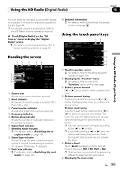
... to the HD Radio tuner's operation manual. % Touch [Digital Radio] on the "AV Source" menu to display the "Digital Radio" screen. = For details concerning operations, refer to Screen switching overview on the next page. Perform seek tuning To perform seek tuning, keep touching [c] or [d], you release the...= For details, refer to Switching the display on page 18. The tuner will start as soon as you can cancel seek tuning by using the navigation system. ception mode on page 105. Otherwise, "A" appears. 9 Seek type indicator = For details, refer to Switching the seek mode on page 105....
... to the HD Radio tuner's operation manual. % Touch [Digital Radio] on the "AV Source" menu to display the "Digital Radio" screen. = For details concerning operations, refer to Screen switching overview on the next page. Perform seek tuning To perform seek tuning, keep touching [c] or [d], you release the...= For details, refer to Switching the display on page 18. The tuner will start as soon as you can cancel seek tuning by using the navigation system. ception mode on page 105. Otherwise, "A" appears. 9 Seek type indicator = For details, refer to Switching the seek mode on page 105....
Owner's Manual
Page 109
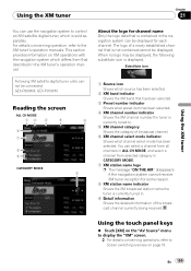
... % Touch [XM] on the "AV Source" menu to display the "XM" screen. = For details concerning operations, refer to Screen switching overview on XM operations with the navigation system which differs from selected category in CATEGORY MODE. 7 XM station name logo p The message "ON THE AIR" ... Source icon Shows which source has been selected. 2 XM band indicator Shows the XM band that is contained in the navigation system can select a channel from all channels in the XM tuner's operation manual. You can be connected: GEX-P900XM, GEX-P910XM Reading the screen ALL CH MODE 12 3 4 5 6 7 ...
... % Touch [XM] on the "AV Source" menu to display the "XM" screen. = For details concerning operations, refer to Screen switching overview on XM operations with the navigation system which differs from selected category in CATEGORY MODE. 7 XM station name logo p The message "ON THE AIR" ... Source icon Shows which source has been selected. 2 XM band indicator Shows the XM band that is contained in the navigation system can select a channel from all channels in the XM tuner's operation manual. You can be connected: GEX-P900XM, GEX-P910XM Reading the screen ALL CH MODE 12 3 4 5 6 7 ...
Owner's Manual
Page 114
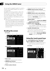
p When you use the navigation system to control a Pioneer Sirius satellite digital tuner, which is sold separately) with navigation system which source has been selected. 2 SIRIUS band indicator Shows the SIRIUS band that described in the SIRIUS tuner's operation manual. Using the touch panel keys % Touch [SIRIUS] on the "AV Source" menu to display the "SIRIUS" screen. = For...
p When you use the navigation system to control a Pioneer Sirius satellite digital tuner, which is sold separately) with navigation system which source has been selected. 2 SIRIUS band indicator Shows the SIRIUS band that described in the SIRIUS tuner's operation manual. Using the touch panel keys % Touch [SIRIUS] on the "AV Source" menu to display the "SIRIUS" screen. = For...
Owner's Manual
Page 121
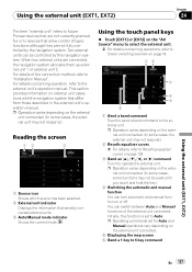
... not be controlled by the navigation system. p Operation varies depending on external unit operations with the navigation system that differ from those described in the external unit's operation manual. Using the external unit (EXT1, EXT2) Chapter 24 The term "external unit" refers to future Pioneer devices that are not currently planned for Auto and Manual operations vary depending on the external...
... not be controlled by the navigation system. p Operation varies depending on external unit operations with the navigation system that differ from those described in the external unit's operation manual. Using the external unit (EXT1, EXT2) Chapter 24 The term "external unit" refers to future Pioneer devices that are not currently planned for Auto and Manual operations vary depending on the external...
Owner's Manual
Page 164
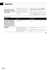
... basic screen (Music) until I'm finished, but you can use the touch interface Voice operation is restricted because the navigation system is fully up- dated. 164 En est encryption code. Radio is incorrectly connected. Please see Operation Manual for safety. Select another screen to operate iPod with the lat- Action (See) Confirm once more information regarding safe...
... basic screen (Music) until I'm finished, but you can use the touch interface Voice operation is restricted because the navigation system is fully up- dated. 164 En est encryption code. Radio is incorrectly connected. Please see Operation Manual for safety. Select another screen to operate iPod with the lat- Action (See) Confirm once more information regarding safe...


