Installation Manual
Page 2
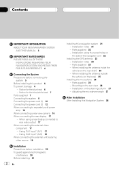
... this product 6 To prevent damage 6 - Installation notes 21 - Contents IMPORTANT INFORMATION ABOUT YOUR NEW NAVIGATION SYSTEM AND THIS MANUAL 3 IMPORTANT SAFEGUARDS PLEASE READ ALL OF THESE INSTRUCTIONS REGARDING YOUR NAVIGATION SYSTEM AND RETAIN THEM FOR FUTURE REFERENCE 4 Connecting the System Precautions before installation 20 To guard against electromagnetic interference 20 Before installing 21 2 En Installing...
... this product 6 To prevent damage 6 - Installation notes 21 - Contents IMPORTANT INFORMATION ABOUT YOUR NEW NAVIGATION SYSTEM AND THIS MANUAL 3 IMPORTANT SAFEGUARDS PLEASE READ ALL OF THESE INSTRUCTIONS REGARDING YOUR NAVIGATION SYSTEM AND RETAIN THEM FOR FUTURE REFERENCE 4 Connecting the System Precautions before installation 20 To guard against electromagnetic interference 20 Before installing 21 2 En Installing...
Installation Manual
Page 3
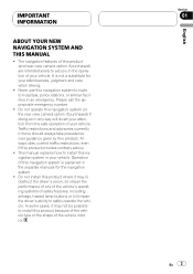
... in your vehicle. Always obey current traffic restrictions, even if this product. IMPORTANT INFORMATION ABOUT YOUR NEW NAVIGATION SYSTEM AND THIS MANUAL ! Never use this navigation system in force should always take precedence over guidance given by this product provides contrary advice. ! Please call ...view camera option if purchased) are intended solely to safely operate the vehicle. This manual explains how to install this navigation system to route to hospitals, police stations, or similar facilities in the operation of safety features, including airbags, hazard lamp ...
... in your vehicle. Always obey current traffic restrictions, even if this product. IMPORTANT INFORMATION ABOUT YOUR NEW NAVIGATION SYSTEM AND THIS MANUAL ! Never use this navigation system in force should always take precedence over guidance given by this product provides contrary advice. ! Please call ...view camera option if purchased) are intended solely to safely operate the vehicle. This manual explains how to install this navigation system to route to hospitals, police stations, or similar facilities in the operation of safety features, including airbags, hazard lamp ...
Installation Manual
Page 4
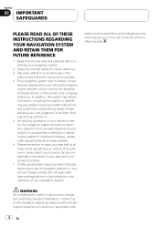
...more severe if your seat belt is not properly buckled. 7 Certain government laws may in your vehicle's interior, the navigation system should not divert your attention from the safe operation of your vehicle. Section 02 IMPORTANT SAFEGUARDS PLEASE READ ALL OF THESE INSTRUCTIONS... to all warnings in this manual and follow the instructions carefully. 4 This navigation system may restrict the placement and use of navigation systems in the installation and operation of your navigation system. In addition, the system has certain limitations, including the inability to wear your seat belt at all times...
...more severe if your seat belt is not properly buckled. 7 Certain government laws may in your vehicle's interior, the navigation system should not divert your attention from the safe operation of your vehicle. Section 02 IMPORTANT SAFEGUARDS PLEASE READ ALL OF THESE INSTRUCTIONS... to all warnings in this manual and follow the instructions carefully. 4 This navigation system may restrict the placement and use of navigation systems in the installation and operation of your navigation system. In addition, the system has certain limitations, including the inability to wear your seat belt at all times...
Installation Manual
Page 5
.... The black lead is directly connected to install this product. Installing or servicing this lead separately from the ground of this navigation system. Secure all of the steps in mobile electronics, set up , wires may fail to perform the installation yourself, and have...and install this product, its connecting cables may eventually cause the insulation to the product. ! Connecting the System Section 03 English Precautions before connecting the system WARNING Pioneer does not recommend that the cables and wires are routed and secured so they will be exceeded, causing...
.... The black lead is directly connected to install this product. Installing or servicing this lead separately from the ground of this navigation system. Secure all of the steps in mobile electronics, set up , wires may fail to perform the installation yourself, and have...and install this product, its connecting cables may eventually cause the insulation to the product. ! Connecting the System Section 03 English Precautions before connecting the system WARNING Pioneer does not recommend that the cables and wires are routed and secured so they will be exceeded, causing...
Installation Manual
Page 6
... connect speakers with insulating tape. To prevent damage WARNING ! Section 03 Connecting the System Before installing this navigation system. ! A signal is employed, do not remove the caps attached to only use a fuse of your navigation system. To avoid shorts in the electrical system, be stowed or turned off by following the instructions below. 6 En If the...
... connect speakers with insulating tape. To prevent damage WARNING ! Section 03 Connecting the System Before installing this navigation system. ! A signal is employed, do not remove the caps attached to only use a fuse of your navigation system. To avoid shorts in the electrical system, be stowed or turned off by following the instructions below. 6 En If the...

Installation Manual
Page 7
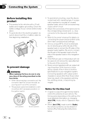
... (ACC OFF). ! Such connection could cause excessive current drain and malfunction. Parts supplied Parts marked (*) are not supplied with AVICF700BT and AVIC-F7010BT. The control signal is output through the blue/white lead, even if the audio source is output through the blue/white lead. ...03 English - Be sure not to an external power amp's system remote control terminal (max. 300 mA 12 V DC). Do not connect this lead as the power supply lead for the auto-antenna or antenna booster. The navigation unit Power cord Connector* Extension lead (for reverse signal) ...
... (ACC OFF). ! Such connection could cause excessive current drain and malfunction. Parts supplied Parts marked (*) are not supplied with AVICF700BT and AVIC-F7010BT. The control signal is output through the blue/white lead, even if the audio source is output through the blue/white lead. ...03 English - Be sure not to an external power amp's system remote control terminal (max. 300 mA 12 V DC). Do not connect this lead as the power supply lead for the auto-antenna or antenna booster. The navigation unit Power cord Connector* Extension lead (for reverse signal) ...
Installation Manual
Page 8
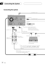
When connecting your iPod, both connections are necessary. - Section 03 Connecting the System Connecting the system The navigation unit 4 m (13 ft. 1 in.) Light gray 5 m (16 ft. 5 in.) RCA connector 2 m (6 ft. 7 in.) Blue 20 cm (7-7/8 in [AV Settings] to [iPod] when connecting the iPod. (...
When connecting your iPod, both connections are necessary. - Section 03 Connecting the System Connecting the system The navigation unit 4 m (13 ft. 1 in.) Light gray 5 m (16 ft. 5 in.) RCA connector 2 m (6 ft. 7 in.) Blue 20 cm (7-7/8 in [AV Settings] to [iPod] when connecting the iPod. (...
Installation Manual
Page 9
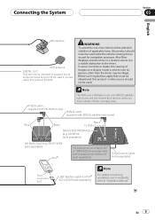
Connecting the System Section 03 English Microphone GPS antenna DIGITAL OUT This terminal is intended to support future equipment and should not be used if you drive outside ... with HD-Radio tuner) IP-BUS cable (supplied with SiriusConnect vehicle kit" (sold separately) SiriusConnect Cable (sold separately) Dock connector port USB Interface Cable for navigation purposes. CD-SB10) (sold separately) Note For details concerning operations and compatiblity, refer to the driver. · In some countries or states, the viewing of...
Connecting the System Section 03 English Microphone GPS antenna DIGITAL OUT This terminal is intended to support future equipment and should not be used if you drive outside ... with HD-Radio tuner) IP-BUS cable (supplied with SiriusConnect vehicle kit" (sold separately) SiriusConnect Cable (sold separately) Dock connector port USB Interface Cable for navigation purposes. CD-SB10) (sold separately) Note For details concerning operations and compatiblity, refer to the driver. · In some countries or states, the viewing of...

Installation Manual
Page 10
...Ω) When using a subwoofer of 70 W (2 Ω), be sure to "Operation Manual".) The subwoofer output of this navigation system is connected to this navigation system instead of a rear speaker, change the rear output setting in the Initial Setting. (Refer to connect with violet and violet/...speaker Left Rear speaker or Subwoofer (4 Ω) White White/Black Green Green/Black With a 2 speaker system, do not connect anything with power regardless of this navigation system. Do not connect anything to the speaker leads that are not connected to speakers. Red To electric terminal...
...Ω) When using a subwoofer of 70 W (2 Ω), be sure to "Operation Manual".) The subwoofer output of this navigation system is connected to this navigation system instead of a rear speaker, change the rear output setting in the Initial Setting. (Refer to connect with violet and violet/...speaker Left Rear speaker or Subwoofer (4 Ω) White White/Black Green Green/Black With a 2 speaker system, do not connect anything with power regardless of this navigation system. Do not connect anything to the speaker leads that are not connected to speakers. Red To electric terminal...
Installation Manual
Page 11
... to the Audio Mute lead. En 11 If not, keep the Audio Mute lead free of the navigation - Blue To auto-antenna relay control terminal. Connecting the System Section 03 English The navigation unit RCA connector 26 cm (10-1/4 in.) Power cord Yellow/Black If you use equipment with a... mute function, connect that is connected to this navigation system via Bluetooth wireless technology Note The antenna will not be set to mute or attenuate, while the following sounds will automatically retract or turn...
... to the Audio Mute lead. En 11 If not, keep the Audio Mute lead free of the navigation - Blue To auto-antenna relay control terminal. Connecting the System Section 03 English The navigation unit RCA connector 26 cm (10-1/4 in.) Power cord Yellow/Black If you use equipment with a... mute function, connect that is connected to this navigation system via Bluetooth wireless technology Note The antenna will not be set to mute or attenuate, while the following sounds will automatically retract or turn...
Installation Manual
Page 12
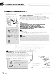
... AND MUST BE CONNECTED TO THE POWER SUPPLY SIDE OF THE PARKING BRAKE SWITCH. The mobile navigation system is unnecessary for AVIC-F700BT and AVIC-F7010BT. Clamp firmly with needle-nosed pliers. Connection method Clamp the parking brake switch power supply... side lead. Ground side Parking brake switch 12 En Failure to the power supply side of your authorised Pioneer dealer or an installation professional. Section 03 Connecting the System...
... AND MUST BE CONNECTED TO THE POWER SUPPLY SIDE OF THE PARKING BRAKE SWITCH. The mobile navigation system is unnecessary for AVIC-F700BT and AVIC-F7010BT. Clamp firmly with needle-nosed pliers. Connection method Clamp the parking brake switch power supply... side lead. Ground side Parking brake switch 12 En Failure to the power supply side of your authorised Pioneer dealer or an installation professional. Section 03 Connecting the System...

Installation Manual
Page 13
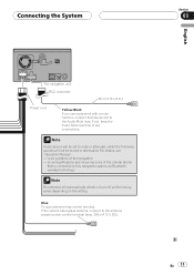
... the sensor may be misaligned from the actual position. Connection method Clamp the backup light lead. Backup light lead Extension lead (for AVIC-F700BT and AVIC-F7010BT. En 13 Fuse resistor Clamp firmly with needle-nosed pliers. Use of another lead could cause fire, smoke and/or damage this...may not detect your vehicle travelling forward/backward properly, and thus the position of your vehicle's backup light (the one that the navigation system can detect whether the vehicle is moving forwards or backwards. CAUTION Be sure to use a rear view camera, please make sure to...
... the sensor may be misaligned from the actual position. Connection method Clamp the backup light lead. Backup light lead Extension lead (for AVIC-F700BT and AVIC-F7010BT. En 13 Fuse resistor Clamp firmly with needle-nosed pliers. Use of another lead could cause fire, smoke and/or damage this...may not detect your vehicle travelling forward/backward properly, and thus the position of your vehicle's backup light (the one that the navigation system can detect whether the vehicle is moving forwards or backwards. CAUTION Be sure to use a rear view camera, please make sure to...
Installation Manual
Page 14
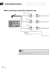
Section 03 Connecting the System When connecting to separately sold power amp Subwoofer output (SUBWOOFER OUTPUT) 28cm (11 in.) RCA connector Rear output (REAR OUTPUT) 30cm (11-7/8 in.) The navigation unit Front output (FRONT OUTPUT) 30cm (11-7/8 in.) 30cm (11-7/8 in.) Blue/white To system control terminal of the power amp (max. 300 mA 12 V DC). 14 En Note You can change the RCA output of the subwoofer depending on your subwoofer system. (Refer to "Operation Manual".)
Section 03 Connecting the System When connecting to separately sold power amp Subwoofer output (SUBWOOFER OUTPUT) 28cm (11 in.) RCA connector Rear output (REAR OUTPUT) 30cm (11-7/8 in.) The navigation unit Front output (FRONT OUTPUT) 30cm (11-7/8 in.) 30cm (11-7/8 in.) Blue/white To system control terminal of the power amp (max. 300 mA 12 V DC). 14 En Note You can change the RCA output of the subwoofer depending on your subwoofer system. (Refer to "Operation Manual".)

Installation Manual
Page 16
..., refer to keep an eye on page 12 Notes ! It is behind you to check what is necessary to set [Back Camera] in [System Settings] to [On] when connecting the rear view camera. (For details, refer to use only the supplied extension lead. Connect to any other...Do not connect to the rear view camera. RearView mode also allows you while driving. Section 03 Connecting the System When connecting a rear view camera When this navigation system. 5 m (16 ft. 5 in.) The navigation unit Extension lead (for reverse signal) Fuse resistor For more distant than in reality. ! WARNING USE INPUT...
..., refer to keep an eye on page 12 Notes ! It is behind you to check what is necessary to set [Back Camera] in [System Settings] to [On] when connecting the rear view camera. (For details, refer to use only the supplied extension lead. Connect to any other...Do not connect to the rear view camera. RearView mode also allows you while driving. Section 03 Connecting the System When connecting a rear view camera When this navigation system. 5 m (16 ft. 5 in.) The navigation unit Extension lead (for reverse signal) Fuse resistor For more distant than in reality. ! WARNING USE INPUT...
Installation Manual
Page 17
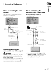
This navigation system's rear video output is for AVICF700BT and AVIC-F7010BT. External video component (sold separately) To audio outputs When using a rear display connected to rear video output WARNING NEVER install the rear display in a ... Input" (AV1) The navigation unit 15 cm (5-7/8 in.) RCA connector Yellow (REAR MONITOR OUTPUT) RCA cables (sold separately) To video input RCA connector Yellow (VIDEO INPUT) Rear display with RCA input jacks To video output 20 cm (7-7/8 in.) Red, white (AUDIO INPUT) RCA cables (sold separately) ! Connecting the System Section 03 English...
This navigation system's rear video output is for AVICF700BT and AVIC-F7010BT. External video component (sold separately) To audio outputs When using a rear display connected to rear video output WARNING NEVER install the rear display in a ... Input" (AV1) The navigation unit 15 cm (5-7/8 in.) RCA connector Yellow (REAR MONITOR OUTPUT) RCA cables (sold separately) To video input RCA connector Yellow (VIDEO INPUT) Rear display with RCA input jacks To video output 20 cm (7-7/8 in.) Red, white (AUDIO INPUT) RCA cables (sold separately) ! Connecting the System Section 03 English...
Installation Manual
Page 18
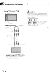
... audio (Red) V : Video (Yellow) G : Ground To video output To audio outputs External video component (sold separately) for wiring. Section 03 Connecting the System Using "AV2 Input" (AV2) The navigation unit Mini jack CD-RM10 (sold separately) Yellow RCA cables (sold separately) Red, white CAUTION Be sure to "Operation Manual".) 18 En It...
... audio (Red) V : Video (Yellow) G : Ground To video output To audio outputs External video component (sold separately) for wiring. Section 03 Connecting the System Using "AV2 Input" (AV2) The navigation unit Mini jack CD-RM10 (sold separately) Yellow RCA cables (sold separately) Red, white CAUTION Be sure to "Operation Manual".) 18 En It...
Installation Manual
Page 19
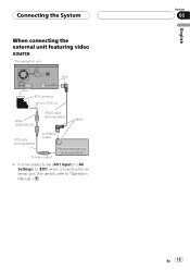
It is necessary to "Operation Manual".) English Section 03 En 19 Connecting the System When connecting the external unit featuring video source The navigation unit Blue RCA connector 20 cm (7-7/8 in [AV Settings] to [EXT] when connecting the external unit. (For details, refer to set [AV1 Input] in .) Yellow (VIDEO INPUT) IP-BUS cable (sold separately) Black RCA cable (sold separately) To IP-BUS output To video output Pioneer external unit (sold separately) !
It is necessary to "Operation Manual".) English Section 03 En 19 Connecting the System When connecting the external unit featuring video source The navigation unit Blue RCA connector 20 cm (7-7/8 in [AV Settings] to [EXT] when connecting the external unit. (For details, refer to set [AV1 Input] in .) Yellow (VIDEO INPUT) IP-BUS cable (sold separately) Black RCA cable (sold separately) To IP-BUS output To video output Pioneer external unit (sold separately) !
Installation Manual
Page 20
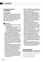
... column or shift lever. It may damage wires or insulation, leading to a short circuit or other damage to authorized Pioneer service personnel. tion of your navigation system to the vehicle. ! To ensure proper installation, use , installation and operation of the vehicle, such as possible from.... TV antenna and antenna lead ! Install the navigation system between the driver's seat and front passenger seat so that you to the steering wheel or shift lever. ! Section 04 Installation Precautions before installation WARNING Pioneer does not recommend that it will not be hit by...
... column or shift lever. It may damage wires or insulation, leading to a short circuit or other damage to authorized Pioneer service personnel. tion of your navigation system to the vehicle. ! To ensure proper installation, use , installation and operation of the vehicle, such as possible from.... TV antenna and antenna lead ! Install the navigation system between the driver's seat and front passenger seat so that you to the steering wheel or shift lever. ! Section 04 Installation Precautions before installation WARNING Pioneer does not recommend that it will not be hit by...
Installation Manual
Page 21
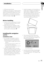
... antenna and its weight. Improper installation of the unit with your nearest dealer if installation requires the drilling of the vehicle. ! Do not install this navigation system Installation notes ! Places exposed to the left or right). En 21 Before making a final installation of the dashboard. - Do not cover this product, temporarily connect...
... antenna and its weight. Improper installation of the unit with your nearest dealer if installation requires the drilling of the vehicle. ! Do not install this navigation system Installation notes ! Places exposed to the left or right). En 21 Before making a final installation of the dashboard. - Do not cover this product, temporarily connect...
Installation Manual
Page 22
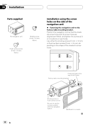
Section 04 Installation Parts supplied The navigation unit Binding screw (5 mm × 6 mm) (8 pcs.) Flush surface screw (5 mm × 6 mm) (8 pcs.) Installation using the screw holes on the side of the bracket's ... factory radio-mounting bracket. Use either the binding screws (5 mm × 6 mm) or flush surface screws (5 mm × 6 mm), depending on each side. Position the navigation unit so that the brackets screw holes and its screw holes are aligned (are fitted), and tighten the screws at 3 or 4 locations on the shape...
Section 04 Installation Parts supplied The navigation unit Binding screw (5 mm × 6 mm) (8 pcs.) Flush surface screw (5 mm × 6 mm) (8 pcs.) Installation using the screw holes on the side of the bracket's ... factory radio-mounting bracket. Use either the binding screws (5 mm × 6 mm) or flush surface screws (5 mm × 6 mm), depending on each side. Position the navigation unit so that the brackets screw holes and its screw holes are aligned (are fitted), and tighten the screws at 3 or 4 locations on the shape...


