Owner s Manual
Page 5
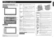
...the available front sources. tion function. Refer to select a menu on page 7 11 Auto EQ microphone input jack Use to connect a microphone for acoustical measurement (sold separately). 12 Detachable faceplate 13 button Press to the next track (chapter). Press ...recogni- Press and hold to perform fast reverse or fast forward. Basic operation Checking part names and functions 8200NEX 7200NEX 1 2 3 4 5 6 78 9 a b 6200NEX 5200NEX 7 9 8 2 3 4 1 5 6 c d 1 LCD screen 2 VOL (+/-) button 3 MAP button Press to the camera view mode. Press and hold to ...
...the available front sources. tion function. Refer to select a menu on page 7 11 Auto EQ microphone input jack Use to connect a microphone for acoustical measurement (sold separately). 12 Detachable faceplate 13 button Press to the next track (chapter). Press ...recogni- Press and hold to perform fast reverse or fast forward. Basic operation Checking part names and functions 8200NEX 7200NEX 1 2 3 4 5 6 78 9 a b 6200NEX 5200NEX 7 9 8 2 3 4 1 5 6 c d 1 LCD screen 2 VOL (+/-) button 3 MAP button Press to the camera view mode. Press and hold to ...
Owner s Manual
Page 69
...: Off, Front-L, Front-R, Front, All. Customizing the equalizer curves p If the preset equalizer curve other than the speaker's maximum input power capability. If a microphone for which you can be made by listening to audio output. 1 Display the "Audio" setting screen. Refer to Displaying the "Audio" setting screen on... You can be adjusted automatically to be adjusted manually only when the listen- The equalizer curves you change the setting for sound to place the microphone in "Custom1" or "Custom2". p If you can recall are incorrectly connected. (For exam-
...: Off, Front-L, Front-R, Front, All. Customizing the equalizer curves p If the preset equalizer curve other than the speaker's maximum input power capability. If a microphone for which you can be made by listening to audio output. 1 Display the "Audio" setting screen. Refer to Displaying the "Audio" setting screen on... You can be adjusted automatically to be adjusted manually only when the listen- The equalizer curves you change the setting for sound to place the microphone in "Custom1" or "Custom2". p If you can recall are incorrectly connected. (For exam-
Owner s Manual
Page 70
...panel of ASL can be connected. When this product. Refer to Checking part names and functions on page 5 6200NEX 5200NEX Plug the microphone into the AUX input jack on page 68 2 Touch [ASL]. 3 Touch the desired level. Low battery Performing Auto EQ CAUTION Do not... the vehicle's acoustics. - p The Bluetooth connection is in incorrect measurement of the vehicle's acoustics. Be sure to use the microphone for acoustical measurement (sold separately). Audio adjustments power to car phones or cellular phones in the vehicle, or remove them in the car changes...
...panel of ASL can be connected. When this product. Refer to Checking part names and functions on page 5 6200NEX 5200NEX Plug the microphone into the AUX input jack on page 68 2 Touch [ASL]. 3 Touch the desired level. Low battery Performing Auto EQ CAUTION Do not... the vehicle's acoustics. - p The Bluetooth connection is in incorrect measurement of the vehicle's acoustics. Be sure to use the microphone for acoustical measurement (sold separately). Audio adjustments power to car phones or cellular phones in the vehicle, or remove them in the car changes...
Installation Manual
Page 2
When using the screw holes on the steering column 32 - For AVIC-8200NEX and AVIC-7200NEX users 26 Installing this product 5 To prevent damage 6 - Contents Precautions Your new product and this manual 3 Important safeguards 3 Connection Precautions ...via the HDMI port (Android device) 19 - Connecting via the MHL port (Android device) 19 Connecting via the HDMI port (iPhone) 16 - Adjusting the microphone angle 32 After installation After installing this product 27 - Notice for the blue/white lead 6 Parts supplied 7 Connecting the power cord (1) 8 Connecting the ...
When using the screw holes on the steering column 32 - For AVIC-8200NEX and AVIC-7200NEX users 26 Installing this product 5 To prevent damage 6 - Contents Precautions Your new product and this manual 3 Important safeguards 3 Connection Precautions ...via the HDMI port (Android device) 19 - Connecting via the MHL port (Android device) 19 Connecting via the HDMI port (iPhone) 16 - Adjusting the microphone angle 32 After installation After installing this product 27 - Notice for the blue/white lead 6 Parts supplied 7 Connecting the power cord (1) 8 Connecting the ...
Installation Manual
Page 7
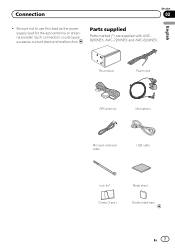
This product Power cord GPS antenna Microphone Mini-jack extension cable USB cable Lock tie* Metal sheet Clamp (3 pcs.) Double-sided tape En 7 Be sure not to use this lead as the power supply lead for the auto-antenna or antenna booster. Connection Section 02 English ! Parts supplied Parts marked (*) are supplied with AVIC8200NEX, AVIC-7200NEX and AVIC-6200NEX. Such connection could cause excessive current drain and malfunction.
This product Power cord GPS antenna Microphone Mini-jack extension cable USB cable Lock tie* Metal sheet Clamp (3 pcs.) Double-sided tape En 7 Be sure not to use this lead as the power supply lead for the auto-antenna or antenna booster. Connection Section 02 English ! Parts supplied Parts marked (*) are supplied with AVIC8200NEX, AVIC-7200NEX and AVIC-6200NEX. Such connection could cause excessive current drain and malfunction.
Installation Manual
Page 12
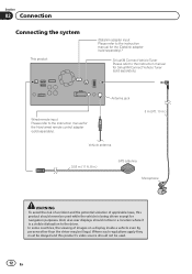
... illegal. Antenna jack Wired remote input Please refer to the instruction manual for navigation purposes. And, also rear displays should not be in .) GPS antenna Microphone WARNING · To avoid the risk of accident and the potential violation of images on a display inside a vehicle even by persons other than the driver...
... illegal. Antenna jack Wired remote input Please refer to the instruction manual for navigation purposes. And, also rear displays should not be in .) GPS antenna Microphone WARNING · To avoid the risk of accident and the potential violation of images on a display inside a vehicle even by persons other than the driver...
Installation Manual
Page 31
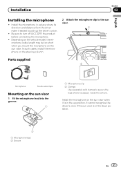
... the sun visor when it easiest to secure the lead where necessary inside the vehicle. Install the microphone in a place where its direction and distance from the driver make it is in the up the driver's voice. ! It cannot recognize the...is in the down position. 2 1 Microphone lead 2 Groove En 31 In such cases, install the microphone on the steering column. 2 Attach the microphone clip to the sun visor. 1 Parts supplied 2 Microphone Double-sided tape Mounting on the sun visor 1 Fit the microphone lead into the groove. 1 1 Microphone clip 2 Clamps Use separately sold clamps ...
... the sun visor when it easiest to secure the lead where necessary inside the vehicle. Install the microphone in a place where its direction and distance from the driver make it is in the up the driver's voice. ! It cannot recognize the...is in the down position. 2 1 Microphone lead 2 Groove En 31 In such cases, install the microphone on the steering column. 2 Attach the microphone clip to the sun visor. 1 Parts supplied 2 Microphone Double-sided tape Mounting on the sun visor 1 Fit the microphone lead into the groove. 1 1 Microphone clip 2 Clamps Use separately sold clamps ...
Installation Manual
Page 32
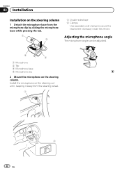
Adjusting the microphone angle The microphone angle can be adjusted. 4 3 1 Microphone 2 Tab 3 Microphone base 4 Microphone clip 2 Mount the microphone on the steering column, keeping it away from the microphone clip by sliding the microphone base while pressing the tab. 1 2 1 Double-sided tape 2 Clamps Use separately sold clamps to secure the lead where necessary inside the vehicle. Install the microphone on the steering column. Section 03 Installation Installation on the steering column 1 Detach the microphone base from the steering wheel. 1 2 32 En
Adjusting the microphone angle The microphone angle can be adjusted. 4 3 1 Microphone 2 Tab 3 Microphone base 4 Microphone clip 2 Mount the microphone on the steering column, keeping it away from the microphone clip by sliding the microphone base while pressing the tab. 1 2 1 Double-sided tape 2 Clamps Use separately sold clamps to secure the lead where necessary inside the vehicle. Install the microphone on the steering column. Section 03 Installation Installation on the steering column 1 Detach the microphone base from the steering wheel. 1 2 32 En

