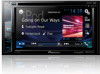

Owner s Manual
Page 6
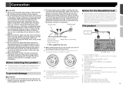
...signifi- The microprocessor must be reset. When using a display connected to V OUT The video output terminal (V OUT) is being transferred. Pioneer cannot guarantee compatibility with the operation of the system. If your product. 2 Receive updates on the latest products and technologies. 3 Download ...or backing into a tight parking spot. WARNING NEVER install the rear display in a location that does not have an ACC wire or circuitry available. CAUTION The rear view mode is erased by persons other than the driver may result in LCD screen malfunction...
...signifi- The microprocessor must be reset. When using a display connected to V OUT The video output terminal (V OUT) is being transferred. Pioneer cannot guarantee compatibility with the operation of the system. If your product. 2 Receive updates on the latest products and technologies. 3 Download ...or backing into a tight parking spot. WARNING NEVER install the rear display in a location that does not have an ACC wire or circuitry available. CAUTION The rear view mode is erased by persons other than the driver may result in LCD screen malfunction...

Owner s Manual
Page 16
... for each device on the type of the line cannot hear the conversation due to be disabled. lular phone, not all cellular phones featuring Bluetooth wire- Registration and connection Cellular phone operations vary depending on page 18 The setting will change after you answer the phone using an iPod / iPhone...
... for each device on the type of the line cannot hear the conversation due to be disabled. lular phone, not all cellular phones featuring Bluetooth wire- Registration and connection Cellular phone operations vary depending on page 18 The setting will change after you answer the phone using an iPod / iPhone...
Owner s Manual
Page 53
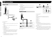
... current capacity of car's body (Another electronic 4 56 Do not route wires where they will be connected to the car separately with insulating tape. If the yellow...feed power to other device must be exposed to device in fire generation of 1 Pioneer navigation system this product to the vehicle battery. Notice for the product to be exceeded...damaged, resulting in .) N STAR N STAR Before installing this product T T (AVH-X5800BHS) (AVH-X4800BS) (AVH-X3800BHS) (AVH-X2800BS) Use this unit or any of this unit with cable clamps or electrical tape. ...
... current capacity of car's body (Another electronic 4 56 Do not route wires where they will be connected to the car separately with insulating tape. If the yellow...feed power to other device must be exposed to device in fire generation of 1 Pioneer navigation system this product to the vehicle battery. Notice for the product to be exceeded...damaged, resulting in .) N STAR N STAR Before installing this product T T (AVH-X5800BHS) (AVH-X4800BS) (AVH-X3800BHS) (AVH-X2800BS) Use this unit or any of this unit with cable clamps or electrical tape. ...
Owner s Manual
Page 54
... green/black leads. b Power supply side c Parking brake switch d Ground side Speaker leads 1 2 c 1 To power supply 2 Power cord 3 Yellow To terminal supplied with Mute function, wire this unit. i Subwoofer (4 Ω) × 2 When a subwoofer is connected to the violet and violet/black leads of this product instead of any connections. This lead... by ignition switch (12 V DC) ON/OFF. 5 Orange/white To lighting switch terminal. 6 Black (ground) To vehicle (metal) body. 7 Violet/white Of the two lead wires connected to the power supply side of the parking brake switch.
... green/black leads. b Power supply side c Parking brake switch d Ground side Speaker leads 1 2 c 1 To power supply 2 Power cord 3 Yellow To terminal supplied with Mute function, wire this unit. i Subwoofer (4 Ω) × 2 When a subwoofer is connected to the violet and violet/black leads of this product instead of any connections. This lead... by ignition switch (12 V DC) ON/OFF. 5 Orange/white To lighting switch terminal. 6 Black (ground) To vehicle (metal) body. 7 Violet/white Of the two lead wires connected to the power supply side of the parking brake switch.
Owner s Manual
Page 57
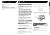
... reference to the factory radiomounting bracket. Leave ample space 5 cm 5 cm Installation using this product to the deployment area of this product, temporarily connect the wiring to confirm that the connections are correct and the system works properly. Connection Installation The appropriate setting is for errors in the vehicle's location display...
... reference to the factory radiomounting bracket. Leave ample space 5 cm 5 cm Installation using this product to the deployment area of this product, temporarily connect the wiring to confirm that the connections are correct and the system works properly. Connection Installation The appropriate setting is for errors in the vehicle's location display...


