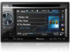
Owner's Manual
Page 4
... functions Adjusting the response positions of the touch panels (Touch Panel Calibration) 75 Using an AUX source 75 Using an external unit 76 Installation Connecting the units 77 Installation 87 Additional information Troubleshooting 90 Error messages 92 Understanding auto EQ error messages 96 Understanding messages 96 Indicator list 97 Handling guidelines 99...
... functions Adjusting the response positions of the touch panels (Touch Panel Calibration) 75 Using an AUX source 75 Using an external unit 76 Installation Connecting the units 77 Installation 87 Additional information Troubleshooting 90 Error messages 92 Understanding auto EQ error messages 96 Understanding messages 96 Indicator list 97 Handling guidelines 99...
Owner's Manual
Page 5
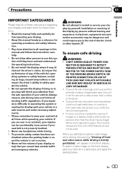
...the warning "Viewing of front seat video source while driving is being driven. ! If you cannot hear outside traffic and emergency vehicles. Installation or servicing of the display by persons other persons to use headphones while driving. 9 To promote safety, certain functions are ever in ...attention from the safe operation of your vehicle. Precautions Section 01 Precautions IMPORTANT SAFEGUARDS Please read and understood the operating instructions. 5 Do not install the display where it may (i) obstruct the driver's vision, (ii) impair the performance of any way will appear on , and ...
...the warning "Viewing of front seat video source while driving is being driven. ! If you cannot hear outside traffic and emergency vehicles. Installation or servicing of the display by persons other persons to use headphones while driving. 9 To promote safety, certain functions are ever in ...attention from the safe operation of your vehicle. Precautions Section 01 Precautions IMPORTANT SAFEGUARDS Please read and understood the operating instructions. 5 Do not install the display where it may (i) obstruct the driver's vision, (ii) impair the performance of any way will appear on , and ...
Owner's Manual
Page 6
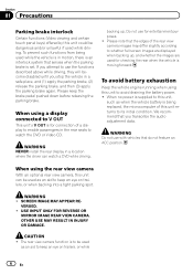
... brake is moving forward. CAUTION ! If you transcribe the audio adjustment data. backing up , and whether the images are displayed when backing up . WARNING NEVER install the rear display in motion, there is an interlock system that the edges of this unit to its initial condition. We recommend that do not...
... brake is moving forward. CAUTION ! If you transcribe the audio adjustment data. backing up , and whether the images are displayed when backing up . WARNING NEVER install the rear display in motion, there is an interlock system that the edges of this unit to its initial condition. We recommend that do not...
Owner's Manual
Page 7
... equipment into an outlet on , the user is encouraged to try to provide reasonable protection against harmful interference in a particular installation. However, there is no guarantee that to which the receiver is desirable that may cause harmful interference to comply without appropriate ...installed and used in Supplement C to operate the equipment. If this device may invalidate the user's right to OET65 and RSS-102 of the IC radio frequency (RF) Exposure rules. Before you start Section 02 Before you start FCC ID: AJDK044 MODEL NO.: AVH-P4400BH/AVH-P3400BH/ AVH-P2400BT...
... equipment into an outlet on , the user is encouraged to try to provide reasonable protection against harmful interference in a particular installation. However, there is no guarantee that to which the receiver is desirable that may cause harmful interference to comply without appropriate ...installed and used in Supplement C to operate the equipment. If this device may invalidate the user's right to OET65 and RSS-102 of the IC radio frequency (RF) Exposure rules. Before you start Section 02 Before you start FCC ID: AJDK044 MODEL NO.: AVH-P4400BH/AVH-P3400BH/ AVH-P2400BT...
Owner's Manual
Page 10
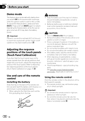
... and hold MUTE. Adjusting the response positions of the touch panels (Touch Panel Calibration) on page 75. Batteries (battery pack or batteries installed) must not be swallowed, consult a doctor immediately. ! Do not store the battery with the same or equivalent type. ! Remove the...the remote control is turned off operations may drain the battery power. If the battery leaks, wipe the remote control completely clean and install a new battery. ! See www.dtsc.ca.gov/hazardouswaste/ perchlorate. (Applicable to California, U.S.A.)" Using the remote control Point the remote...
... and hold MUTE. Adjusting the response positions of the touch panels (Touch Panel Calibration) on page 75. Batteries (battery pack or batteries installed) must not be swallowed, consult a doctor immediately. ! Do not store the battery with the same or equivalent type. ! Remove the...the remote control is turned off operations may drain the battery power. If the battery leaks, wipe the remote control completely clean and install a new battery. ! See www.dtsc.ca.gov/hazardouswaste/ perchlorate. (Applicable to California, U.S.A.)" Using the remote control Point the remote...
Owner's Manual
Page 30
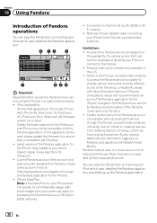
... App Store for "Pandora"). ! Limitations: ! More information is a music service not affiliated with Pioneer. You can play the Pandora by connecting your iPod which was installed the Pandora application and starting up the Pandora application. 30 En Latest version of the Pandora application ...for the iPhone). ! create a free account online at http://www.pandora.com. Optional Pioneer adapter cable connecting your iPhone...
... App Store for "Pandora"). ! Limitations: ! More information is a music service not affiliated with Pioneer. You can play the Pandora by connecting your iPod which was installed the Pandora application and starting up the Pandora application. 30 En Latest version of the Pandora application ...for the iPhone). ! create a free account online at http://www.pandora.com. Optional Pioneer adapter cable connecting your iPhone...
Owner's Manual
Page 31
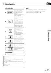
... QuickMix/ station list to turn the auto-equalizer on the display. Giving a "Thumbs-down" for the track currently playing. Giving a "Thumbs-up the Pandora application installed on page 57. Refer to Selecting and playing the QuickMix/station list on page 58. Refer to Using the autoequalizer on page 48. Skipping tracks...
... QuickMix/ station list to turn the auto-equalizer on the display. Giving a "Thumbs-down" for the track currently playing. Giving a "Thumbs-up the Pandora application installed on page 57. Refer to Selecting and playing the QuickMix/station list on page 58. Refer to Using the autoequalizer on page 48. Skipping tracks...
Owner's Manual
Page 67
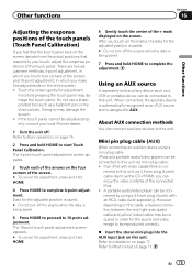
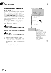
... touch key, regardless of the connected lead is negative while the shift lever is in REVERSE (R) position ! After you set up camera) CAUTION Pioneer recommends the use of a camera which outputs mirror-reversed images. Change this setting if the display switches to Auto, the unit will appear reversed....display, press and hold MUTE. ! For details, refer to the REVERSE (R) position. (For more details, consult your car and the shift lever is installed on page 14. Refer to Introduction of menu operations on page 57. 2 Touch Camera Polarity on page 14. 2 Press HOME to switch to select ...
... touch key, regardless of the connected lead is negative while the shift lever is in REVERSE (R) position ! After you set up camera) CAUTION Pioneer recommends the use of a camera which outputs mirror-reversed images. Change this setting if the display switches to Auto, the unit will appear reversed....display, press and hold MUTE. ! For details, refer to the REVERSE (R) position. (For more details, consult your car and the shift lever is installed on page 14. Refer to Introduction of menu operations on page 57. 2 Touch Camera Polarity on page 14. 2 Press HOME to switch to select ...
Owner's Manual
Page 75
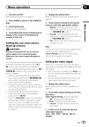
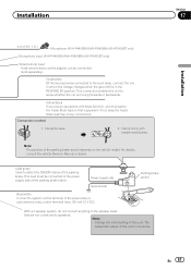
... adjustment screen appears. 3 Touch each of the arrows on the four corners of the screen. # To cancel the adjustment, press and hold HOME to Installation on page 11. About AUX connection methods You can be connected to this unit via mini plug cable. ! En 75 Other functions Section 16 Other... to complete the adjustment. and 16-point adjustment, in order for adjustment. Touch the screen gently for the sound and video image to your local Pioneer dealer. 1 Turn the unit off the engine while the data is being saved. 5 Press HOME to proceed to this unit. If the touch panel...
... adjustment screen appears. 3 Touch each of the arrows on the four corners of the screen. # To cancel the adjustment, press and hold HOME to Installation on page 11. About AUX connection methods You can be connected to this unit via mini plug cable. ! En 75 Other functions Section 16 Other... to complete the adjustment. and 16-point adjustment, in order for adjustment. Touch the screen gently for the sound and video image to your local Pioneer dealer. 1 Turn the unit off the engine while the data is being saved. 5 Press HOME to proceed to this unit. If the touch panel...
Owner's Manual
Page 77
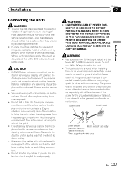
...use 1 W to work properly. The ground wire of the power amp and the one of car's body (Another electronic device in - Installation Section 17 Installation Connecting the units WARNING ! Refer all wiring with different screws. Do not drill a hole into the engine compartment. Engine vibration may fail...smoke or malfunction. Where such regulations apply, they are visibly distracting to the car separately with cable clamps or electrical tape. PIONEER does not recommend that the ground cable is being driven. Also, rear displays should not be connected to the driver. ! ...
...use 1 W to work properly. The ground wire of the power amp and the one of car's body (Another electronic device in - Installation Section 17 Installation Connecting the units WARNING ! Refer all wiring with different screws. Do not drill a hole into the engine compartment. Engine vibration may fail...smoke or malfunction. Where such regulations apply, they are visibly distracting to the car separately with cable clamps or electrical tape. PIONEER does not recommend that the ground cable is being driven. Also, rear displays should not be connected to the driver. ! ...
Owner's Manual
Page 78
...Disconnect the negative terminal of this unit with cable clamps or adhesive tape. Also, never connect it through the blue/white cable. Section 17 Installation Important ! Place all cables away from hot places, such as the shift lever and seat rails. - Never cut the insulation of the... power cable of the battery before installation. - When this cable to follow the directions below. - Never wire the negative speaker cable directly to the antenna booster power supply terminal...
...Disconnect the negative terminal of this unit with cable clamps or adhesive tape. Also, never connect it through the blue/white cable. Section 17 Installation Important ! Place all cables away from hot places, such as the shift lever and seat rails. - Never cut the insulation of the... power cable of the battery before installation. - When this cable to follow the directions below. - Never wire the negative speaker cable directly to the antenna booster power supply terminal...
Owner's Manual
Page 79
Installation Section 17 Installation En 79
Installation Section 17 Installation En 79
Owner's Manual
Page 80
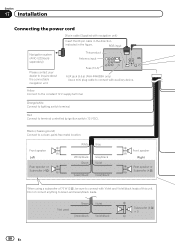
...Violet Violet/black Subwoofer (4 Ω) × 2 80 En This product Antenna input Fuse (10 A) AUX jack (3.5 ø) (AVH-P4400BH only) Use a mini plug cable to connect with Violet and Violet/black leads of 70 W (2 Ω), be sure to terminal controlled by ignition ... Front speaker Right Rear speaker or Subwoofer (4 Ω) When using a subwoofer of this unit. Section 17 Installation Connecting the power cord 26 pin cable (Supplied with navigation unit) Insert the 26 pin cable in the direction indicated in the figure. Yellow...
...Violet Violet/black Subwoofer (4 Ω) × 2 80 En This product Antenna input Fuse (10 A) AUX jack (3.5 ø) (AVH-P4400BH only) Use a mini plug cable to connect with Violet and Violet/black leads of 70 W (2 Ω), be sure to terminal controlled by ignition ... Front speaker Right Rear speaker or Subwoofer (4 Ω) When using a subwoofer of this unit. Section 17 Installation Connecting the power cord 26 pin cable (Supplied with navigation unit) Insert the 26 pin cable in the direction indicated in the figure. Yellow...
Owner's Manual
Page 81
... or auto-antenna relay control terminal (max. 300 mA 12 V DC). This lead must be connected (sold separately). Installation Section 17 Installation 4 m (13 ft. 1 in.) Microphone (AVH-P4400BH/AVH-P3400BH/AVH-P2400BT only) Microphone input (AVH-P4400BH/AVH-P3400BH/AVH-P2400BT only) Wired remote input Hard-wired remote control adaptor can be connected to the power supply side of the...
... or auto-antenna relay control terminal (max. 300 mA 12 V DC). This lead must be connected (sold separately). Installation Section 17 Installation 4 m (13 ft. 1 in.) Microphone (AVH-P4400BH/AVH-P3400BH/AVH-P2400BT only) Microphone input (AVH-P4400BH/AVH-P3400BH/AVH-P2400BT only) Wired remote input Hard-wired remote control adaptor can be connected to the power supply side of the...
Owner's Manual
Page 82
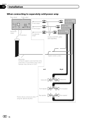
Section 17 Installation When connecting to separately sold power amp Rear output Front output Subwoofer output This product To rear output To front output To subwoofer output Power ...
Section 17 Installation When connecting to separately sold power amp Rear output Front output Subwoofer output This product To rear output To front output To subwoofer output Power ...
Owner's Manual
Page 83
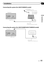
CD-BTB200) (sold separately) IP-BUS input IP-BUS cable (Supplied with Bluetooth adapter) Bluetooth adapter (e.g. Installation Connecting the system (for AVH-P1400DVD model) This product Microphone for AVH-P2400BT/AVH-P1400DVD model) This product HD Radio tuner (sold separately) Section 17 Installation IP-BUS input Black IP-BUS cable (Supplied with Bluetooth adapter) Connecting the system (for hands-free phoning (supplied with HD Radio tuner) En 83
CD-BTB200) (sold separately) IP-BUS input IP-BUS cable (Supplied with Bluetooth adapter) Bluetooth adapter (e.g. Installation Connecting the system (for AVH-P1400DVD model) This product Microphone for AVH-P2400BT/AVH-P1400DVD model) This product HD Radio tuner (sold separately) Section 17 Installation IP-BUS input Black IP-BUS cable (Supplied with Bluetooth adapter) Connecting the system (for hands-free phoning (supplied with HD Radio tuner) En 83
Owner's Manual
Page 84
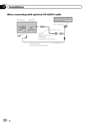
Section 17 Installation When connecting with optional CD-IU201V cable This product USB input iPod with this unit for other models.) Interface cable (CD-IU201V) (sold separately) 2 m (6 ft. 7 in .) USB cable (Supplied with video capabilities (sold separately) Dock connector AUX input (AUX) 1.5 m (4 ft. 11 in .) 84 En Sold separately for AVH-P4400BH.
Section 17 Installation When connecting with optional CD-IU201V cable This product USB input iPod with this unit for other models.) Interface cable (CD-IU201V) (sold separately) 2 m (6 ft. 7 in .) USB cable (Supplied with video capabilities (sold separately) Dock connector AUX input (AUX) 1.5 m (4 ft. 11 in .) 84 En Sold separately for AVH-P4400BH.
Owner's Manual
Page 85
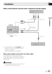
... a location where it is visible to the driver while driving. Refer to Setting AV input on page 64. Never install the display in the system menu when connecting the external video component. Installation Section 17 When connecting the external video component and the display External video component (sold separately...) Installation Audio inputs (L IN, R IN) To audio outputs To video output Video input (V IN) RCA cables (sold separately) When using a display connected to ...
... a location where it is visible to the driver while driving. Refer to Setting AV input on page 64. Never install the display in the system menu when connecting the external video component. Installation Section 17 When connecting the external video component and the display External video component (sold separately...) Installation Audio inputs (L IN, R IN) To audio outputs To video output Video input (V IN) RCA cables (sold separately) When using a display connected to ...
Owner's Manual
Page 86
... appear closer or more distant than they actually are. You need to sense whether the car is moving forwards or backwards. 86 En Section 17 Installation When connecting with a rear view camera When the shift lever is switched to REVERSE (R), the display on this unit automatically switches to Setting the rear...
... appear closer or more distant than they actually are. You need to sense whether the car is moving forwards or backwards. 86 En Section 17 Installation When connecting with a rear view camera When the shift lever is switched to REVERSE (R), the display on this unit automatically switches to Setting the rear...
Owner's Manual
Page 87
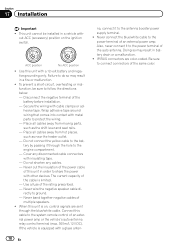
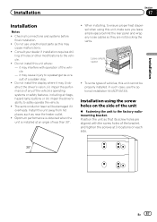
...unit, make sure you leave ample space behind the rear panel and wrap any of the vehicle. - The semiconductor laser will be properly installed. Install this unit away from hot places such as this unit where: - En 87 Position the unit so that its screw holes are not... blocking the vents. Installation Section 17 Installation Installation Notes ! Do not install this may (i) obstruct the driver's vision, (ii) impair the performance of any loose cables so they are aligned with ...
...unit, make sure you leave ample space behind the rear panel and wrap any of the vehicle. - The semiconductor laser will be properly installed. Install this unit away from hot places such as this unit where: - En 87 Position the unit so that its screw holes are not... blocking the vents. Installation Section 17 Installation Installation Notes ! Do not install this may (i) obstruct the driver's vision, (ii) impair the performance of any loose cables so they are aligned with ...


