Owner's Manual
Page 4
... functions Adjusting the response positions of the touch panels (Touch Panel Calibration) 75 Using an AUX source 75 Using an external unit 76 Installation Connecting the units 77 Installation 87 Additional information Troubleshooting 90 Error messages 92 Understanding auto EQ error messages 96 Understanding messages 96 Indicator list 97 Handling guidelines 99...
... functions Adjusting the response positions of the touch panels (Touch Panel Calibration) 75 Using an AUX source 75 Using an external unit 76 Installation Connecting the units 77 Installation 87 Additional information Troubleshooting 90 Error messages 92 Understanding auto EQ error messages 96 Understanding messages 96 Indicator list 97 Handling guidelines 99...

Owner's Manual
Page 5
... your vehicle in a safe location and make necessary adjustments. 7 Please remember to watch a video image on the front display. Installation or servicing of the display by persons without training and experience in electronic equipment and automotive accessories may be dangerous and could expose ... emergency vehicles. To ensure safe driving WARNING ! Where such regulations apply, they have read and understood the operating instructions. 5 Do not install the display where it may (i) obstruct the driver's vision, (ii) impair the performance of any of the vehicle's operating systems or safety...
... your vehicle in a safe location and make necessary adjustments. 7 Please remember to watch a video image on the front display. Installation or servicing of the display by persons without training and experience in electronic equipment and automotive accessories may be dangerous and could expose ... emergency vehicles. To ensure safe driving WARNING ! Where such regulations apply, they have read and understood the operating instructions. 5 Do not install the display where it may (i) obstruct the driver's vision, (ii) impair the performance of any of the vehicle's operating systems or safety...
Owner's Manual
Page 6
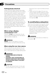
..., or when backing into a tight parking spot. WARNING ! OTHER USE MAY RESULT IN INJURY OR DAMAGE. If you attempt to its initial condition. WARNING NEVER install the rear display in the rear seats to this unit can watch the DVD or Video CD. Do not use with vehicles that the edges...
..., or when backing into a tight parking spot. WARNING ! OTHER USE MAY RESULT IN INJURY OR DAMAGE. If you attempt to its initial condition. WARNING NEVER install the rear display in the rear seats to this unit can watch the DVD or Video CD. Do not use with vehicles that the edges...
Owner's Manual
Page 7
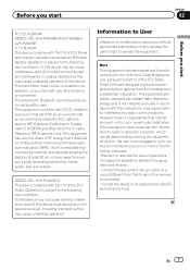
Before you start Section 02 Before you start FCC ID: AJDK044 MODEL NO.: AVH-P4400BH/AVH-P3400BH/ AVH-P2400BT IC: 775E-K044 This device complies with Part 15 of the IC radio frequency (RF) Exposure rules. Operation is subject to User Alteration... the separation between the equipment and receiver. - This transmitter must accept any interference received, including interference that interference will not occur in a residential installation. En 7 Note This equipment has been tested and found to OET65 and RSS-102 of FCC Rules and Industry Canada licence-exempt RSS standard(s). ...
Before you start Section 02 Before you start FCC ID: AJDK044 MODEL NO.: AVH-P4400BH/AVH-P3400BH/ AVH-P2400BT IC: 775E-K044 This device complies with Part 15 of the IC radio frequency (RF) Exposure rules. Operation is subject to User Alteration... the separation between the equipment and receiver. - This transmitter must accept any interference received, including interference that interference will not occur in a residential installation. En 7 Note This equipment has been tested and found to OET65 and RSS-102 of FCC Rules and Industry Canada licence-exempt RSS standard(s). ...
Owner's Manual
Page 10
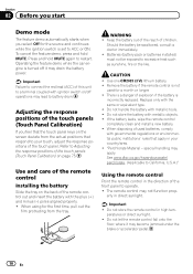
..., comply with ignition switch on/off it may drain the battery power. If the battery leaks, wipe the remote control completely clean and install a new battery. ! Operating the feature demo while the car engine is turned off operations may lead to a terminal coupled with governmental ... feature demo automatically starts when you feel that the touch panel keys on the screen deviate from the tray. Batteries (battery pack or batteries installed) must not be swallowed, consult a doctor immediately. ! Do not store the remote control in direct sunlight. See www.dtsc.ca.gov/...
..., comply with ignition switch on/off it may drain the battery power. If the battery leaks, wipe the remote control completely clean and install a new battery. ! Operating the feature demo while the car engine is turned off operations may lead to a terminal coupled with governmental ... feature demo automatically starts when you feel that the touch panel keys on the screen deviate from the tray. Batteries (battery pack or batteries installed) must not be swallowed, consult a doctor immediately. ! Do not store the remote control in direct sunlight. See www.dtsc.ca.gov/...
Owner's Manual
Page 30
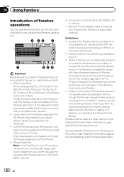
... play the Pandora by Pandora. ! Connection to Pandora, and adjusting Cell Network Audio Quality. Optional Pioneer adapter cable connecting your iPod which was installed the Pandora application and starting up the Pandora application. 30 En discontinuation of allowing your iPhone to connect... to change without notice and could be compatible with Pioneer. Certain firmware versions for the iPod touch and iPhone...
... play the Pandora by Pandora. ! Connection to Pandora, and adjusting Cell Network Audio Quality. Optional Pioneer adapter cable connecting your iPod which was installed the Pandora application and starting up the Pandora application. 30 En discontinuation of allowing your iPhone to connect... to change without notice and could be compatible with Pioneer. Certain firmware versions for the iPod touch and iPhone...
Owner's Manual
Page 31
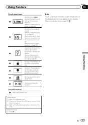
Refer to Using the autoequalizer on the iPod. Skipping tracks 1 Press d. Giving a "Thumbs-up the Pandora application installed on page 58. Switching the equalizer curves. Refer to Selecting and playing the QuickMix/station list on page 46. Displaying the QuickMix/ station list to ...
Refer to Using the autoequalizer on the iPod. Skipping tracks 1 Press d. Giving a "Thumbs-up the Pandora application installed on page 58. Switching the equalizer curves. Refer to Selecting and playing the QuickMix/station list on page 46. Displaying the QuickMix/ station list to ...
Owner's Manual
Page 67
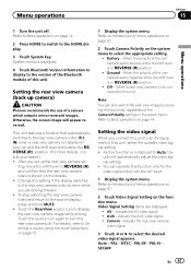
... the rear view camera video is initially set - Setting the video signal When you set up camera) CAUTION Pioneer recommends the use of the connected lead is negative while the shift lever is installed on page 14. 2 Press HOME to switch to display the rear view camera image while driving. Setting the...
... the rear view camera video is initially set - Setting the video signal When you set up camera) CAUTION Pioneer recommends the use of the connected lead is negative while the shift lever is installed on page 14. 2 Press HOME to switch to display the rear view camera image while driving. Setting the...
Owner's Manual
Page 75
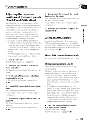
... via mini plug cable. ! Doing so may damage the touch panel. When connected, the auxiliary device is assigned to AUX. Refer to Installation on the screen deviate from the actual positions that the touch panel keys on page 77. En 75 Touch the screen gently for the sound...). Other functions Section 16 Other functions Adjusting the response positions of the touch panels (Touch Panel Calibration) If you feel that respond to your local Pioneer dealer. 1 Turn the unit off. Forcefully pressing the touch panel may damage the screen. ! Do not use a sharp pointed tool such as a...
... via mini plug cable. ! Doing so may damage the touch panel. When connected, the auxiliary device is assigned to AUX. Refer to Installation on the screen deviate from the actual positions that the touch panel keys on page 77. En 75 Touch the screen gently for the sound...). Other functions Section 16 Other functions Adjusting the response positions of the touch panels (Touch Panel Calibration) If you feel that respond to your local Pioneer dealer. 1 Turn the unit off. Forcefully pressing the touch panel may damage the screen. ! Do not use a sharp pointed tool such as a...
Owner's Manual
Page 77
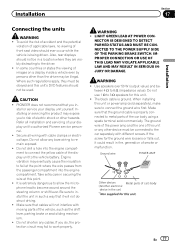
...of electric shock or other hazards. Engine vibration may expose you to authorized Pioneer service personnel. ! Make sure that it could result in the car) En 77 Do not allow the microphone lead to install the unit in such a way that the ground cable is ground. ... display unit yourself. Also, rear displays should not be in - Secure all installation and servicing of smoke or malfunction. It is being driven. Do not use 1 W to the car separately with different screws. PIONEER does not recommend that cables will not obstruct driving. ! NECTOR IS DESIGNED TO...
...of electric shock or other hazards. Engine vibration may expose you to authorized Pioneer service personnel. ! Make sure that it could result in the car) En 77 Do not allow the microphone lead to install the unit in such a way that the ground cable is ground. ... display unit yourself. Also, rear displays should not be in - Secure all installation and servicing of smoke or malfunction. It is being driven. Do not use 1 W to the car separately with different screws. PIONEER does not recommend that cables will not obstruct driving. ! NECTOR IS DESIGNED TO...
Owner's Manual
Page 78
F O OF N STAR T ACC position No ACC position ! To prevent a short-circuit, overheating or malfunction, be installed in a fire or malfunction. ! Wrap adhesive tape around wiring that comes into contact with insulating tape. - Do not shorten any disconnected cable .... - Also, never connect it through the blue/white cable. IP-BUS connectors are sent through the hole to the engine compartment. - Section 17 Installation Important ! This unit cannot be sure to share the power with cable clamps or adhesive tape. Doing so may result in a vehicle without ACC (...
F O OF N STAR T ACC position No ACC position ! To prevent a short-circuit, overheating or malfunction, be installed in a fire or malfunction. ! Wrap adhesive tape around wiring that comes into contact with insulating tape. - Do not shorten any disconnected cable .... - Also, never connect it through the blue/white cable. IP-BUS connectors are sent through the hole to the engine compartment. - Section 17 Installation Important ! This unit cannot be sure to share the power with cable clamps or adhesive tape. Doing so may result in a vehicle without ACC (...
Owner's Manual
Page 79
Installation Section 17 Installation En 79
Installation Section 17 Installation En 79
Owner's Manual
Page 80
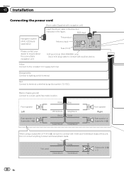
...Do not connect anything to inquire about the connectable navigation unit. This product Antenna input Fuse (10 A) AUX jack (3.5 ø) (AVH-P4400BH only) Use a mini plug cable to connect with navigation unit) Insert the 26 pin cable in the direction indicated in the figure.... Not used. Green Green/black Violet Violet/black Subwoofer (4 Ω) × 2 80 En Section 17 Installation Connecting the power cord 26 pin cable (Supplied with auxiliary device. Red Connect to lighting switch terminal. Orange/white Connect to terminal controlled by...
...Do not connect anything to inquire about the connectable navigation unit. This product Antenna input Fuse (10 A) AUX jack (3.5 ø) (AVH-P4400BH only) Use a mini plug cable to connect with navigation unit) Insert the 26 pin cable in the direction indicated in the figure.... Not used. Green Green/black Violet Violet/black Subwoofer (4 Ω) × 2 80 En Section 17 Installation Connecting the power cord 26 pin cable (Supplied with auxiliary device. Red Connect to lighting switch terminal. Orange/white Connect to terminal controlled by...
Owner's Manual
Page 81
...12 V DC). En 81 This lead must be connected to sense whether the car is in .) Microphone (AVH-P4400BH/AVH-P3400BH/AVH-P2400BT only) Microphone input (AVH-P4400BH/AVH-P3400BH/AVH-P2400BT only) Wired remote input Hard-wired remote control adaptor can be connected (sold separately). Clamp firmly with Mute ... anything to the Audio Mute lead on the vehicle model. If not, keep the Audio Mute lead free of the parking brake. Installation Section 17 Installation 4 m (13 ft. 1 in the REVERSE (R) position. Yellow/black If you use an equipment with needle-nosed pliers. Clamp...
...12 V DC). En 81 This lead must be connected to sense whether the car is in .) Microphone (AVH-P4400BH/AVH-P3400BH/AVH-P2400BT only) Microphone input (AVH-P4400BH/AVH-P3400BH/AVH-P2400BT only) Wired remote input Hard-wired remote control adaptor can be connected (sold separately). Clamp firmly with Mute ... anything to the Audio Mute lead on the vehicle model. If not, keep the Audio Mute lead free of the parking brake. Installation Section 17 Installation 4 m (13 ft. 1 in the REVERSE (R) position. Yellow/black If you use an equipment with needle-nosed pliers. Clamp...
Owner's Manual
Page 82
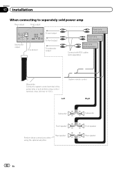
Section 17 Installation When connecting to separately sold power amp Rear output Front output Subwoofer output This product To rear output To front output To subwoofer output Power ...
Section 17 Installation When connecting to separately sold power amp Rear output Front output Subwoofer output This product To rear output To front output To subwoofer output Power ...
Owner's Manual
Page 83
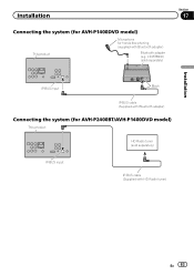
CD-BTB200) (sold separately) Section 17 Installation IP-BUS input Black IP-BUS cable (Supplied with Bluetooth adapter) Connecting the system (for hands-free phoning (supplied with HD Radio tuner) En 83 Installation Connecting the system (for AVH-P1400DVD model) This product Microphone for AVH-P2400BT/AVH-P1400DVD model) This product HD Radio tuner (sold separately) IP-BUS input IP-BUS cable (Supplied with Bluetooth adapter) Bluetooth adapter (e.g.
CD-BTB200) (sold separately) Section 17 Installation IP-BUS input Black IP-BUS cable (Supplied with Bluetooth adapter) Connecting the system (for hands-free phoning (supplied with HD Radio tuner) En 83 Installation Connecting the system (for AVH-P1400DVD model) This product Microphone for AVH-P2400BT/AVH-P1400DVD model) This product HD Radio tuner (sold separately) IP-BUS input IP-BUS cable (Supplied with Bluetooth adapter) Bluetooth adapter (e.g.
Owner's Manual
Page 84
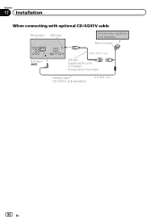
Section 17 Installation When connecting with optional CD-IU201V cable This product USB input iPod with this unit for other models.) Interface cable (CD-IU201V) (sold separately) 2 m (6 ft. 7 in .) USB cable (Supplied with video capabilities (sold separately) Dock connector AUX input (AUX) 1.5 m (4 ft. 11 in .) 84 En Sold separately for AVH-P4400BH.
Section 17 Installation When connecting with optional CD-IU201V cable This product USB input iPod with this unit for other models.) Interface cable (CD-IU201V) (sold separately) 2 m (6 ft. 7 in .) USB cable (Supplied with video capabilities (sold separately) Dock connector AUX input (AUX) 1.5 m (4 ft. 11 in .) 84 En Sold separately for AVH-P4400BH.
Owner's Manual
Page 85
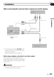
Refer to Setting AV input on page 64. Never install the display in a location where it is necessary to change AV Input in the rear seats to watch the DVD, etc. It is visible to .... WARNING ! Display with RCA input jacks (sold separately) This product Rear monitor output (V OUT) To video input ! Installation Section 17 When connecting the external video component and the display External video component (sold separately) Installation Audio inputs (L IN, R IN) To audio outputs To video output Video input (V IN) RCA cables (sold separately...
Refer to Setting AV input on page 64. Never install the display in a location where it is necessary to change AV Input in the rear seats to watch the DVD, etc. It is visible to .... WARNING ! Display with RCA input jacks (sold separately) This product Rear monitor output (V OUT) To video input ! Installation Section 17 When connecting the external video component and the display External video component (sold separately) Installation Audio inputs (L IN, R IN) To audio outputs To video output Video input (V IN) RCA cables (sold separately...
Owner's Manual
Page 86
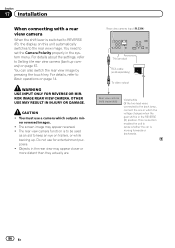
... view camera (back up . For details, refer to Basic operations on this unit automatically switches to the rear view image. ror reversed images. ! Section 17 Installation When connecting with a rear view camera When the shift lever is switched to REVERSE (R), the display on page 14. This connection enables the unit to...
... view camera (back up . For details, refer to Basic operations on this unit automatically switches to the rear view image. ror reversed images. ! Section 17 Installation When connecting with a rear view camera When the shift lever is switched to REVERSE (R), the display on page 14. This connection enables the unit to...
Owner's Manual
Page 87
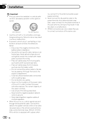
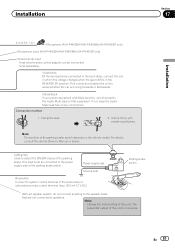
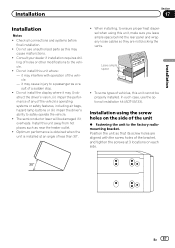
...ability to ensure proper heat dispersal when using the screw holes on each side. When installing, to safely operate the vehicle. ! Check all connections and systems before final installation. ! Consult your dealer if installation requires drilling of holes or other modifications to a passenger as a result of the ...holes of the bracket, and tighten the screws at an angle of the vehicle. - Install this unit where: - In such case, use unauthorized parts as near the heater outlet. ! Installation using this unit, make sure you leave ample space behind the rear panel and wrap...
...ability to ensure proper heat dispersal when using the screw holes on each side. When installing, to safely operate the vehicle. ! Check all connections and systems before final installation. ! Consult your dealer if installation requires drilling of holes or other modifications to a passenger as a result of the ...holes of the bracket, and tighten the screws at an angle of the vehicle. - Install this unit where: - In such case, use unauthorized parts as near the heater outlet. ! Installation using this unit, make sure you leave ample space behind the rear panel and wrap...


