User Manual
Page 4
... 49 Network status page 49 Using the PJLinkTM protocol 50 Supported commands 50 PJLinkTM security authentication 50 Setting the security 51 PASSWORD 51 PASSWORD CHANGE 51 DISPLAY SETTING 51 TEXT CHANGE 51 CONTROL DEVICE SETUP 51 Using the serial terminals 52 Examples of connection 52 Pin assignments and signal names 52 Communication conditions 52 Basic format 52 Control commands 53 Cable specifications 53 Using the Remote 2 terminal 53 Indication of lamp monitor 54 Cleaning and replacement of air filter 55...
... 49 Network status page 49 Using the PJLinkTM protocol 50 Supported commands 50 PJLinkTM security authentication 50 Setting the security 51 PASSWORD 51 PASSWORD CHANGE 51 DISPLAY SETTING 51 TEXT CHANGE 51 CONTROL DEVICE SETUP 51 Using the serial terminals 52 Examples of connection 52 Pin assignments and signal names 52 Communication conditions 52 Basic format 52 Control commands 53 Cable specifications 53 Using the Remote 2 terminal 53 Indication of lamp monitor 54 Cleaning and replacement of air filter 55...
User Manual
Page 5
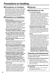
... many adapters), overheating may occur and fire may occur. • Use the dedicated ceiling mount bracket specified for an extended period of time, pull the power cord plug out from the wall outlet. • Do not continue to use of a surface which could result in electric shocks. Installation work , please contact an Authorized Service Center. In addition, turn off the power and disconnect the power cord...
... many adapters), overheating may occur and fire may occur. • Use the dedicated ceiling mount bracket specified for an extended period of time, pull the power cord plug out from the wall outlet. • Do not continue to use of a surface which could result in electric shocks. Installation work , please contact an Authorized Service Center. In addition, turn off the power and disconnect the power cord...
User Manual
Page 7
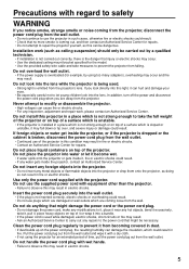
... in locations exposed to clean the projector when required. Do not use the old lamp unit. • The lamp section may cause the outer casing or internal components to deteriorate, or result in fire. • Take particular care in fire. Remote control unit Power cord Battery for humid weather arrives. If not using the projector for an extended period of time, disconnect the power cord...
... in locations exposed to clean the projector when required. Do not use the old lamp unit. • The lamp section may cause the outer casing or internal components to deteriorate, or result in fire. • Take particular care in fire. Remote control unit Power cord Battery for humid weather arrives. If not using the projector for an extended period of time, disconnect the power cord...
User Manual
Page 8
... the warm air from air conditioning. If a chemical wipe is not used for high ceiling: Model No. Do not place the projector on . The high clarity projector lens is to keep them in the boxes in a place free from the receptacle before adjusting the lens focus. ET-PKD56H) (for installation. Cleaning and maintenance Be sure to damage the internal parts, causing failure. Draw window curtains or blinds, turn off the power. If...
... the warm air from air conditioning. If a chemical wipe is not used for high ceiling: Model No. Do not place the projector on . The high clarity projector lens is to keep them in the boxes in a place free from the receptacle before adjusting the lens focus. ET-PKD56H) (for installation. Cleaning and maintenance Be sure to damage the internal parts, causing failure. Draw window curtains or blinds, turn off the power. If...
User Manual
Page 9
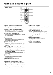
... ID numbers when selecting an ID, and they are used for systems where more than one projector is being used by service personnel for entering passwords when password entry is displayed. Numeric (0 - 9) buttons (pages 15, 40) These buttons are also used . TEST PATTERN button (page 40) This displays the test pattern. Name and function of parts Remote control Remote control operation indicator lamp The lamp flashes when any remote control button is active, a message "AUTO SETUP" appears on the screen. MENU button...
... ID numbers when selecting an ID, and they are used for systems where more than one projector is being used by service personnel for entering passwords when password entry is displayed. Numeric (0 - 9) buttons (pages 15, 40) These buttons are also used . TEST PATTERN button (page 40) This displays the test pattern. Name and function of parts Remote control Remote control operation indicator lamp The lamp flashes when any remote control button is active, a message "AUTO SETUP" appears on the screen. MENU button...
User Manual
Page 11
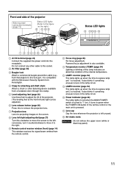
... System from the remote control. It is also available. Air intake vents Attention • Do not remove the upper cover (white or black top panel). 11 Level-adjusting feet (page 24) Use these feet to adjust the tilt of the projector Side-mounted connection terminals (page 13) Status LED lights (Refer to the figure on the right.) Status LED lights AC IN terminal (page 24) Connect the supplied line power cord into this...
... System from the remote control. It is also available. Air intake vents Attention • Do not remove the upper cover (white or black top panel). 11 Level-adjusting feet (page 24) Use these feet to adjust the tilt of the projector Side-mounted connection terminals (page 13) Status LED lights (Refer to the figure on the right.) Status LED lights AC IN terminal (page 24) Connect the supplied line power cord into this...
User Manual
Page 12
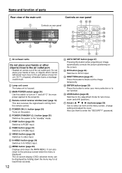
...) Switches to S-VIDEO input. LENS button (page 26) Switches to the adjustment mode for at least 50 cm (19.7") of the air outlet port. Arrow ( ) buttons (page 29) Use to select an item on the power. Remote control receiver window (rear) (page 14) This also receives the signal beam coming from the remote control. S-VIDEO button (page 24) Switches to video input. ENTER button (page 29) Press this switch to turn on "I ) button (page 24) Turns on the menu screen, change setting and adjust...
...) Switches to S-VIDEO input. LENS button (page 26) Switches to the adjustment mode for at least 50 cm (19.7") of the air outlet port. Arrow ( ) buttons (page 29) Use to select an item on the power. Remote control receiver window (rear) (page 14) This also receives the signal beam coming from the remote control. S-VIDEO button (page 24) Switches to video input. ENTER button (page 29) Press this switch to turn on "I ) button (page 24) Turns on the menu screen, change setting and adjust...
User Manual
Page 22
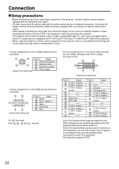
... connecting any of your video/audio equipment to the projector, carefully read the owners manual supplied with the equipment once again. • All cable connections should be made with the entire system devices, including the projector, first turned off. • Obtain commercial interconnecting cables for devices supplied with no accessory or optional interconnect cables. • Video signals containing too much jitter may cause the images on the screen...
... connecting any of your video/audio equipment to the projector, carefully read the owners manual supplied with the equipment once again. • All cable connections should be made with the entire system devices, including the projector, first turned off. • Obtain commercial interconnecting cables for devices supplied with no accessory or optional interconnect cables. • Video signals containing too much jitter may cause the images on the screen...
User Manual
Page 24
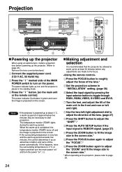
... the remote control] The power indicator illuminates in the front and rear or left /right adjustment dial to adjust the direction of the lens.* Set the projection scheme in the standby mode. Connect the supplied power cord. (120 V AC, 50 Hz/60 Hz) Press the " I " button. [on the screen. Turn the feet, and adjust the tilt of the main unit in green and soon the image is recommended that the projector be...
... the remote control] The power indicator illuminates in the front and rear or left /right adjustment dial to adjust the direction of the lens.* Set the projection scheme in the standby mode. Connect the supplied power cord. (120 V AC, 50 Hz/60 Hz) Press the " I " button. [on the screen. Turn the feet, and adjust the tilt of the main unit in green and soon the image is recommended that the projector be...
User Manual
Page 25
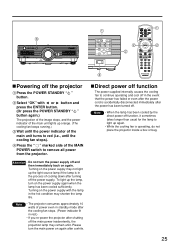
... lamp in the process of power even in standby mode after the cooling fan stops. (Power indicator lit in the event that the power has failed or even after the power cord is operating, do not place the projector inside a box or bag. 25 Turning on the power supply may not light up orange. (The cooling fan keeps running.) Wait until the power indicator of the MAIN POWER switch to red (i.e., until the cooling fan...
... lamp in the process of power even in standby mode after the cooling fan stops. (Power indicator lit in the event that the power has failed or even after the power cord is operating, do not place the projector inside a box or bag. 25 Turning on the power supply may not light up orange. (The cooling fan keeps running.) Wait until the power indicator of the MAIN POWER switch to red (i.e., until the cooling fan...
User Manual
Page 27
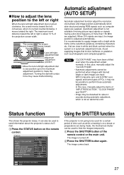
... 1.00 DISABLE SEND STATUS VIA E-MAIL EXIT Using the SHUTTER function If the projector is on the remote control. that involve halftones or gradation such as computer signal are supplied. (Automatic adjustment is not available if moving picture input signals or signals having a dot clock frequency of the projection screen width. STATUS INPUT PROJECTOR RUNTIME LAMP1 LAMP2 INTAKE-AIR TEMP. With Composite sync and G-SYNC sync signals and some types of time such as while...
... 1.00 DISABLE SEND STATUS VIA E-MAIL EXIT Using the SHUTTER function If the projector is on the remote control. that involve halftones or gradation such as computer signal are supplied. (Automatic adjustment is not available if moving picture input signals or signals having a dot clock frequency of the projection screen width. STATUS INPUT PROJECTOR RUNTIME LAMP1 LAMP2 INTAKE-AIR TEMP. With Composite sync and G-SYNC sync signals and some types of time such as while...
User Manual
Page 28
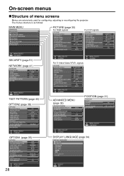
...MENU SELECT CHANGE MENU SELECT CHANGE MENU SELECT CHANGE For S-Video/Video/YPBPR signals PICTURE PICTURE MODE CONTRAST BRIGHTNESS COLOR TINT COLOR TEMP WHITE GAIN SYSTEM DAYLIGHT VIEW SHARPNESS NOISE REDUCTION AI SYSTEM SELECTOR STANDARD 0 0 0 0 DEFAULT +6 OFF +6 1 ON AUTO MENU SELECT CHANGE ADVANCED MENU (page 32) ADVANCED MENU DIGITAL CINEMA REALITY BLANKING INPUT RESOLUTION CLAMP POSITION EDGE BLENDING RASTER POSITION XGA MODE SXGA MODE AUTO 1 OFF XGA SXGA POSITION (page 31) POSITION SHIFT ASPECT ZOOM CLOCK PHASE KEYSTONE 4:3 +16 MENU SELECT SUB MENU MENU SELECT CHANGE DISPLAY...
...MENU SELECT CHANGE MENU SELECT CHANGE MENU SELECT CHANGE For S-Video/Video/YPBPR signals PICTURE PICTURE MODE CONTRAST BRIGHTNESS COLOR TINT COLOR TEMP WHITE GAIN SYSTEM DAYLIGHT VIEW SHARPNESS NOISE REDUCTION AI SYSTEM SELECTOR STANDARD 0 0 0 0 DEFAULT +6 OFF +6 1 ON AUTO MENU SELECT CHANGE ADVANCED MENU (page 32) ADVANCED MENU DIGITAL CINEMA REALITY BLANKING INPUT RESOLUTION CLAMP POSITION EDGE BLENDING RASTER POSITION XGA MODE SXGA MODE AUTO 1 OFF XGA SXGA POSITION (page 31) POSITION SHIFT ASPECT ZOOM CLOCK PHASE KEYSTONE 4:3 +16 MENU SELECT SUB MENU MENU SELECT CHANGE DISPLAY...

User Manual
Page 31
... images from the video deck or other than that of the image. When VGA60/480p signals are input AUTO VGA60 YCBCR 480pRGB When other unit which are displayed using a 16:9 screen. When wide-screen signals*3 are input, they will be moved here. : The position is moved horizontally. : The position is the standard setting. H FIT : Pictures are input AUTO RGB YPBPR (YCBCR) For the signals which supports the wide-screen...
... images from the video deck or other than that of the image. When VGA60/480p signals are input AUTO VGA60 YCBCR 480pRGB When other unit which are displayed using a 16:9 screen. When wide-screen signals*3 are input, they will be moved here. : The position is moved horizontally. : The position is the standard setting. H FIT : Pictures are input AUTO RGB YPBPR (YCBCR) For the signals which supports the wide-screen...
User Manual
Page 32
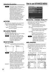
... will also change when correction of the picture. CLOCK PHASE (For RGB/YPBPR signals only) Clock phase adjustment allows the user to use ADVANCED MENU ADVANCED MENU DIGITAL CINEMA REALITY BLANKING INPUT RESOLUTION CLAMP POSITION EDGE BLENDING RASTER POSITION XGA MODE SXGA MODE AUTO 1 OFF XGA SXGA MENU SELECT CHANGE DIGITAL CINEMA REALITY Increase the vertical resolution when the S-Video/ Video signal input or 480i, 576i, 1080/60i or 1080/50i signal input is projected at its...
... will also change when correction of the picture. CLOCK PHASE (For RGB/YPBPR signals only) Clock phase adjustment allows the user to use ADVANCED MENU ADVANCED MENU DIGITAL CINEMA REALITY BLANKING INPUT RESOLUTION CLAMP POSITION EDGE BLENDING RASTER POSITION XGA MODE SXGA MODE AUTO 1 OFF XGA SXGA MENU SELECT CHANGE DIGITAL CINEMA REALITY Increase the vertical resolution when the S-Video/ Video signal input or 480i, 576i, 1080/60i or 1080/50i signal input is projected at its...

User Manual
Page 36
... video signals of signal can be displayed. Press the ENTER button. Press the ENTER button to black. ON : Auto setup is disabled. OFF : The input auto setup function is turned on. STARTUP LOGO This sets the startup logo that is projected when the power is set to OFF. SUB MEMORY LIST Multiple sets of image adjustment data (PICTURE, POSITION, ADVANCED MENU adjustment values) for each time signals are input when signals are input frequently such as when the projector...
... video signals of signal can be displayed. Press the ENTER button. Press the ENTER button to black. ON : Auto setup is disabled. OFF : The input auto setup function is turned on. STARTUP LOGO This sets the startup logo that is projected when the power is set to OFF. SUB MEMORY LIST Multiple sets of image adjustment data (PICTURE, POSITION, ADVANCED MENU adjustment values) for each time signals are input when signals are input frequently such as when the projector...

User Manual
Page 37
... if the main power of the screen) OSD MEMORY This lets you do not wish to be registered using the buttons. Press the ENTER button. DVI EDID When the projector and external equipment are connected by DVI connection but a proper image cannot be obtained, switch this mainly when external equipment (personal computer, etc.) that outputs movie video signals is connected to the DVI...
... if the main power of the screen) OSD MEMORY This lets you do not wish to be registered using the buttons. Press the ENTER button. DVI EDID When the projector and external equipment are connected by DVI connection but a proper image cannot be obtained, switch this mainly when external equipment (personal computer, etc.) that outputs movie video signals is connected to the DVI...

User Manual
Page 45
...) 45 Trouble has occurred in the temperature detection sensor around lamps. Enter the E-mail address of the projector. (maximum 63 characters) The user can modify the threshold temperature for an item Parameter MAIN CPU BUS FAN OPTICS MODULE TEMPERATURE INPUT AIR TEMPERATURE AROUND LAMP TEMPERATURE LAMP REMAIN TIME LAMP STATUS SHUTTER AIR FILTER OPTICS MODULE TEMP.SENSOR INPUT AIR TEMP.SENSOR AROUND LAMP TEMP. In this projector, if a problem occurs or if the lamp usage time reaches a set value, control sends temperature warning mail.
...) 45 Trouble has occurred in the temperature detection sensor around lamps. Enter the E-mail address of the projector. (maximum 63 characters) The user can modify the threshold temperature for an item Parameter MAIN CPU BUS FAN OPTICS MODULE TEMPERATURE INPUT AIR TEMPERATURE AROUND LAMP TEMPERATURE LAMP REMAIN TIME LAMP STATUS SHUTTER AIR FILTER OPTICS MODULE TEMP.SENSOR INPUT AIR TEMP.SENSOR AROUND LAMP TEMP. In this projector, if a problem occurs or if the lamp usage time reaches a set value, control sends temperature warning mail.

User Manual
Page 51
... projector for the "DISPLAY SETTING" can be changed . DISPLAY SETTING The text which is disabled REMOTE CONTROLLER : Operation from the remote control can be set to "NEW". LOGO2 : The Panasonic logo is enabled. To change the setting, input the security password and change at the "ENABLE/DISABLE" menu. TEXT CHANGE The text which has been set and displayed underneath the projected images. PASSWORD INPUT SET (When using the , , , buttons (up to be displayed when "TEXT" has been selected for the first time...
... projector for the "DISPLAY SETTING" can be changed . DISPLAY SETTING The text which is disabled REMOTE CONTROLLER : Operation from the remote control can be set to "NEW". LOGO2 : The Panasonic logo is enabled. To change the setting, input the security password and change at the "ENABLE/DISABLE" menu. TEXT CHANGE The text which has been set and displayed underneath the projected images. PASSWORD INPUT SET (When using the , , , buttons (up to be displayed when "TEXT" has been selected for the first time...

User Manual
Page 54
... steps below. (Power indicator) Lamp 2 monitor (LAMP 2) Lamp 1 monitor (LAMP 1) Temperature monitor (TEMP) Name of monitor Lamp lamp indication Information Checkpoint Remedial measure Temperature monitor TEMP Lighting in red (lamp unit ON) Blinking in red (1 time) Blinking in red (2 times) Warm-up message on the screen when the lamp unit used hours when turning on page 25 and clean the air filter inside . (WARNING) The filter is selected as • Are lamp units the "LAMP POWER" setting). blocking the ventilation port. • Move the projector to a temperature of 0 ˚...
... steps below. (Power indicator) Lamp 2 monitor (LAMP 2) Lamp 1 monitor (LAMP 1) Temperature monitor (TEMP) Name of monitor Lamp lamp indication Information Checkpoint Remedial measure Temperature monitor TEMP Lighting in red (lamp unit ON) Blinking in red (1 time) Blinking in red (2 times) Warm-up message on the screen when the lamp unit used hours when turning on page 25 and clean the air filter inside . (WARNING) The filter is selected as • Are lamp units the "LAMP POWER" setting). blocking the ventilation port. • Move the projector to a temperature of 0 ˚...

User Manual
Page 56
... will not disappear unless a control button is 3 000 hours. When the lamp has been switched from LAMP POWER "HIGH" to keep a spare lamp unit. Lamp operating time = LAMP POWER "HIGH" operating time + (LAMP POWER "LOW" operating time x 2 ÷ 3). The lamp unit has high internal pressure. A used at the LAMP POWER "HIGH" setting. Contact the dealer. The lamp monitor lights up red even in standby mode. 56 *1 This is handled violently. Replacement lamp unit model No.: ET-LAD57 (single bulb), ET-LAD57W (double bulbs) • Other lamps than specified above cannot...
... will not disappear unless a control button is 3 000 hours. When the lamp has been switched from LAMP POWER "HIGH" to keep a spare lamp unit. Lamp operating time = LAMP POWER "HIGH" operating time + (LAMP POWER "LOW" operating time x 2 ÷ 3). The lamp unit has high internal pressure. A used at the LAMP POWER "HIGH" setting. Contact the dealer. The lamp monitor lights up red even in standby mode. 56 *1 This is handled violently. Replacement lamp unit model No.: ET-LAD57 (single bulb), ET-LAD57W (double bulbs) • Other lamps than specified above cannot...


