Multi-media Display
Page 3
... maximum life of time between lightings, etc. may result in the projection display becoming unstable, possibly causing injury. (2) This projection display should be regulated in your community due to the characteristics and use for the PT-50LC13/PT-60LC13. Disposal of company or product trademarks, these materials may cease ...) WARNING AS WITH ANY SMALL OBJECT, SD CARDS CAN BE SWALLOWED BY YOUNG CHILDREN. The lamp should not be used with -TV Noise Reduction for good stereo separation and audio fidelity. DO NOT ALLOW CHILDREN TO HANDLE THE SD CARD. It also contains...
... maximum life of time between lightings, etc. may result in the projection display becoming unstable, possibly causing injury. (2) This projection display should be regulated in your community due to the characteristics and use for the PT-50LC13/PT-60LC13. Disposal of company or product trademarks, these materials may cease ...) WARNING AS WITH ANY SMALL OBJECT, SD CARDS CAN BE SWALLOWED BY YOUNG CHILDREN. The lamp should not be used with -TV Noise Reduction for good stereo separation and audio fidelity. DO NOT ALLOW CHILDREN TO HANDLE THE SD CARD. It also contains...

Multi-media Display
Page 4
... while connecting the projection display to provide reasonable protection against harmful interference in a particular installation. Visit our Panasonic Web Site for...an outlet on the rear cover of the FCC Rules. Declaration of Conformity Models Number: PT-50LC13/PT-60LC13 Trade Name: Panasonic Responsible party: Matsushita Electric... Corporation of enjoyment from that interference will have many years of America. However, there is connected. • Consult the dealer or an experienced radio / TV...
... while connecting the projection display to provide reasonable protection against harmful interference in a particular installation. Visit our Panasonic Web Site for...an outlet on the rear cover of the FCC Rules. Declaration of Conformity Models Number: PT-50LC13/PT-60LC13 Trade Name: Panasonic Responsible party: Matsushita Electric... Corporation of enjoyment from that interference will have many years of America. However, there is connected. • Consult the dealer or an experienced radio / TV...

Multi-media Display
Page 8
...39, 41) 8 For assistance, please call : 1-888-VIEW PTV(843-9788) Location of Controls Illuminated Remote Control POWER button Press to turn the projection display ON or OFF. (P. 22) MUTE button Press this button to mute the sound. (P. 36) Mode Selection buttons Selects the operation mode for ...Control AUX Mode Selection for Remote Control Receiver / Amplifier Mode Selection for Remote Control Digital Broadcasting Satellite for Remote Control Cable TV Mode Selection for Remote Control PC/MENU button RGB input mode is displayed in single screen. (P. 31) R-TUNE button Press to view...
...39, 41) 8 For assistance, please call : 1-888-VIEW PTV(843-9788) Location of Controls Illuminated Remote Control POWER button Press to turn the projection display ON or OFF. (P. 22) MUTE button Press this button to mute the sound. (P. 36) Mode Selection buttons Selects the operation mode for ...Control AUX Mode Selection for Remote Control Receiver / Amplifier Mode Selection for Remote Control Digital Broadcasting Satellite for Remote Control Cable TV Mode Selection for Remote Control PC/MENU button RGB input mode is displayed in single screen. (P. 31) R-TUNE button Press to view...
Multi-media Display
Page 9
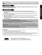
...The screen below is displayed for 5 seconds. (P. 31) NORMAL STEREO SAP MONO CH 1 2 ABC When the Menu screen is displayed. (P. 32) TV/VIDEO button Toggles between TV and VIDEO inputs. (P. 35) SAP button Changes the audio mode. (P. 37) Light button Lights all buttons. Display menu Press the ACTION button to... normal viewing from the MENU screen. Note: This section describes TV mode only. Increase volume. Returns to display Menu screen. Changes to the right during menu mode. The selected mode button...
...The screen below is displayed for 5 seconds. (P. 31) NORMAL STEREO SAP MONO CH 1 2 ABC When the Menu screen is displayed. (P. 32) TV/VIDEO button Toggles between TV and VIDEO inputs. (P. 35) SAP button Changes the audio mode. (P. 37) Light button Lights all buttons. Display menu Press the ACTION button to... normal viewing from the MENU screen. Note: This section describes TV mode only. Increase volume. Returns to display Menu screen. Changes to the right during menu mode. The selected mode button...
Multi-media Display
Page 13
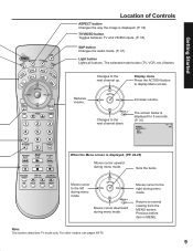
A cable converter box is required for its compatibility requirements. • For reception of the projection display. Installation Cable Connection Use this configuration when connecting the projection display to the VHF/UHF terminal on the back of cable channels (01 - 125) connect the cable supplied by your local Cable company ...cable from cable Notes: • Certain cable systems offset some channels to CABLE. (P. 26) 13 In from the antenna or cable system to a cable TV system. Antenna Mode must be set to reduce interference or have Premium (scrambled) channels.
A cable converter box is required for its compatibility requirements. • For reception of the projection display. Installation Cable Connection Use this configuration when connecting the projection display to the VHF/UHF terminal on the back of cable channels (01 - 125) connect the cable supplied by your local Cable company ...cable from cable Notes: • Certain cable systems offset some channels to CABLE. (P. 26) 13 In from the antenna or cable system to a cable TV system. Antenna Mode must be set to reduce interference or have Premium (scrambled) channels.

Multi-media Display
Page 14
This does not apply when signal is connected to the projection display VHF/UHF terminal via a cable box or VCR, set the TV channel to the Antenna input terminal on the back of the VCR. Connect the cable from VIDEO INPUT. ...ON THE BACK OF THE CABLE BOX Or ↑ TO VCR ↑ TO VCR Incoming Cable from Antenna or Cable TV System CABLE BOX Note: When the RF coaxial cable is input from the Output terminal on the back of the Cable ...the Antenna / Cable to the RF in Terminal (VCR) Use this configuration when connecting the projection display to a cable TV system using VCR.
This does not apply when signal is connected to the projection display VHF/UHF terminal via a cable box or VCR, set the TV channel to the Antenna input terminal on the back of the VCR. Connect the cable from VIDEO INPUT. ...ON THE BACK OF THE CABLE BOX Or ↑ TO VCR ↑ TO VCR Incoming Cable from Antenna or Cable TV System CABLE BOX Note: When the RF coaxial cable is input from the Output terminal on the back of the Cable ...the Antenna / Cable to the RF in Terminal (VCR) Use this configuration when connecting the projection display to a cable TV system using VCR.
Multi-media Display
Page 15
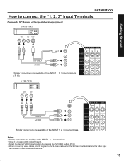
... at the INPUT 1, 2, 3 input terminals. • Input 3 is located on the side of the unit. • Select the desired VIDEO input position by pressing the TV/VIDEO button. (P. 35) • When connecting video cables, priority is given to connect the "1, 2, 3" Input Terminals Connects VCRs and other peripheral equipment (S-VHS VCR) S-VIDEO...
... at the INPUT 1, 2, 3 input terminals. • Input 3 is located on the side of the unit. • Select the desired VIDEO input position by pressing the TV/VIDEO button. (P. 35) • When connecting video cables, priority is given to connect the "1, 2, 3" Input Terminals Connects VCRs and other peripheral equipment (S-VHS VCR) S-VIDEO...

Multi-media Display
Page 16
... (Y, PB, PR) that can be input are available at the COMPONENT VIDEO INPUT 1-4 Terminals. • Select the desired COMPONENT VIDEO INPUT position by pressing the TV/VIDEO button. (P. 35) • Component video signals that can be Input Mode type 480i No. DVD Player COMPONENT VIDEO AUDIO Notes: • Similar connections are...
... (Y, PB, PR) that can be input are available at the COMPONENT VIDEO INPUT 1-4 Terminals. • Select the desired COMPONENT VIDEO INPUT position by pressing the TV/VIDEO button. (P. 35) • Component video signals that can be Input Mode type 480i No. DVD Player COMPONENT VIDEO AUDIO Notes: • Similar connections are...
Multi-media Display
Page 17
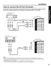
Getting Started Installation How to the same video recorder, as the main picture on the projection display screen and sound from the S-Video IN terminal. 17 A sub-picture, including channel search, etc., will not be output. • VIDEO OUT terminals will ...not output Y, PB, PR, RGB/DIGITAL IN or SD/PC card signals. • The S-Video OUT terminal outputs the same signal that time, e.g. TV programs or signals from INPUT 1, 2, 3 terminals. Recording Equipment (S-VHS VCR) S-VIDEO Or VIDEO AUDIO Stereo System (A Stereo Amplifier and Speakers) AUDIO Notes: •...
Getting Started Installation How to the same video recorder, as the main picture on the projection display screen and sound from the S-Video IN terminal. 17 A sub-picture, including channel search, etc., will not be output. • VIDEO OUT terminals will ...not output Y, PB, PR, RGB/DIGITAL IN or SD/PC card signals. • The S-Video OUT terminal outputs the same signal that time, e.g. TV programs or signals from INPUT 1, 2, 3 terminals. Recording Equipment (S-VHS VCR) S-VIDEO Or VIDEO AUDIO Stereo System (A Stereo Amplifier and Speakers) AUDIO Notes: •...
Multi-media Display
Page 18
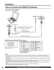
.... To obtain the optimum picture quality with PC / AT compatible D-SUB 15P terminal. • The computer shown in the illustration is for computers with the projection display, a vertical scanning frequency of 62 Hz is input. Signal name 1R 2G 3B 4 NC 5 NC 6 Ground for R 7 Ground for G 8 Ground for PC ... a cable which are above or below the specified frequency range. • Select the desired RGB input position by pressing the PC/MENU or TV/VIDEO button. (P. 35) • Similar connections are not supplied with this set. • The picture will become dark if an PC signal with a...
.... To obtain the optimum picture quality with PC / AT compatible D-SUB 15P terminal. • The computer shown in the illustration is for computers with the projection display, a vertical scanning frequency of 62 Hz is input. Signal name 1R 2G 3B 4 NC 5 NC 6 Ground for R 7 Ground for G 8 Ground for PC ... a cable which are above or below the specified frequency range. • Select the desired RGB input position by pressing the PC/MENU or TV/VIDEO button. (P. 35) • Similar connections are not supplied with this set. • The picture will become dark if an PC signal with a...
Multi-media Display
Page 19
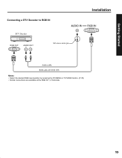
Getting Started Connecting a DTV Decoder to RGB IN DTV Decoder RGB OUT AUDIO OUT M3 stereo mini pin Installation Audio cable RGB cable (D-SUB 15P) Notes: • Select the desired RGB input position by pressing the PC/MENU or TV/VIDEO button. (P. 35) • Similar connections are available at the RGB IN 1, 2 Terminals. 19
Getting Started Connecting a DTV Decoder to RGB IN DTV Decoder RGB OUT AUDIO OUT M3 stereo mini pin Installation Audio cable RGB cable (D-SUB 15P) Notes: • Select the desired RGB input position by pressing the PC/MENU or TV/VIDEO button. (P. 35) • Similar connections are available at the RGB IN 1, 2 Terminals. 19
Multi-media Display
Page 20
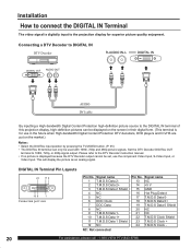
... connect the DIGITAL IN Terminal The video signal is digitally input to the projection display for use in the future when High-bandwidth Digital Content Protection DTV decoders...picture signals. Set the DTV Decoder DIGITAL OUT terminal to the DIGITAL IN terminal of this projection display, high-definition pictures can be displayed on the market.) Notes: • Select the DIGITAL... input position by pressing the TV/VIDEO button. (P. 35) • The DIGITAL IN terminal can only be set, use the component Video ...
... connect the DIGITAL IN Terminal The video signal is digitally input to the projection display for use in the future when High-bandwidth Digital Content Protection DTV decoders...picture signals. Set the DTV Decoder DIGITAL OUT terminal to the DIGITAL IN terminal of this projection display, high-definition pictures can be displayed on the market.) Notes: • Select the DIGITAL... input position by pressing the TV/VIDEO button. (P. 35) • The DIGITAL IN terminal can only be set, use the component Video ...
Multi-media Display
Page 26
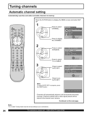
.... 3 Press to select ADJUST SET UP CHANNEL. Press to display the CHANNEL. LANGUAGE :ENGLISH CHANNEL LOCK CAPTION VIDEO OTHER Press to run AUTO SET. Note: TV or Cable Tuning mode must be stored in progress, press the SWAP button. Channel numbers with a video signal present will automatically advance until all channels...
.... 3 Press to select ADJUST SET UP CHANNEL. Press to display the CHANNEL. LANGUAGE :ENGLISH CHANNEL LOCK CAPTION VIDEO OTHER Press to run AUTO SET. Note: TV or Cable Tuning mode must be stored in progress, press the SWAP button. Channel numbers with a video signal present will automatically advance until all channels...
Multi-media Display
Page 28
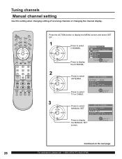
... setting Use this setting when changing setting of receiving channels or changing the channel display. LANGUAGE :ENGLISH CHANNEL LOCK CAPTION VIDEO OTHER Press to select TV or CABLE. PAGE SELECT END 2 Press to select SET UP CHANNEL MANUAL SET. SELECT EXIT Continued on the next page. 28 For assistance, please call...
... setting Use this setting when changing setting of receiving channels or changing the channel display. LANGUAGE :ENGLISH CHANNEL LOCK CAPTION VIDEO OTHER Press to select TV or CABLE. PAGE SELECT END 2 Press to select SET UP CHANNEL MANUAL SET. SELECT EXIT Continued on the next page. 28 For assistance, please call...

Multi-media Display
Page 30
.../ POWER indicator Volume up(+) / down(-) buttons Remote Control Sensor 1 Channel up / down buttons Press to operate the projection display with the remote control. 2 Press to turn the projection display on. 3 Press to select CABLE TV 125 or 69 the desired CH 01 channel. (Or use number keys ) CH 02 Or CH 125 Note...
.../ POWER indicator Volume up(+) / down(-) buttons Remote Control Sensor 1 Channel up / down buttons Press to operate the projection display with the remote control. 2 Press to turn the projection display on. 3 Press to select CABLE TV 125 or 69 the desired CH 01 channel. (Or use number keys ) CH 02 Or CH 125 Note...
Multi-media Display
Page 31
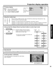
... 1 * RGB 1 VIDEO 2 * COMPONENT 4 * VIDEO 3 * COMPONENT 3 * COMPONENT 1 * COMPONENT 2 * Auto shut off automatically. Basic Operation TV status display Press the RECALL button, except when the MENU screen is displayed, to the set's tuner for terminals with the number keys, first ...press the 1 key, and then enter the remaining two digits. FREEZE Example: Invalid operation was tried during FREEZE mode. 31 Projection display operation Aspect types (P. 32) Receivable broadcast types (P. 37) NORMAL STEREO SAP MONO CH 1 2 ABC Channel Channel caption (P. 54) Using...
... 1 * RGB 1 VIDEO 2 * COMPONENT 4 * VIDEO 3 * COMPONENT 3 * COMPONENT 1 * COMPONENT 2 * Auto shut off automatically. Basic Operation TV status display Press the RECALL button, except when the MENU screen is displayed, to the set's tuner for terminals with the number keys, first ...press the 1 key, and then enter the remaining two digits. FREEZE Example: Invalid operation was tried during FREEZE mode. 31 Projection display operation Aspect types (P. 32) Receivable broadcast types (P. 37) NORMAL STEREO SAP MONO CH 1 2 ABC Channel Channel caption (P. 54) Using...

Multi-media Display
Page 35
...displayed. COMPONENT 2 * RGB 1 COMPONENT 4 * COMPONENT 3 * RGB input mode is displayed. VIDEO 2 Signal of the projection display. DIGITAL IN Signal of source connected to INPUT 2 is selected. RGB 2 Signal of source connected to COMPONENT VIDEO INPUT... Signal of source connected to CARD SLOT is displayed. COMPONENT 4 Signal of source connected to INPUT 3 is displayed. TV CARD VIDEO 1 * DIGITAL IN 2 The input mode changes each time this button is VIDEO 2 * RGB 2 ... the connected equipment. 35 RGB 1 Signal of source connected to the rear terminals.
...displayed. COMPONENT 2 * RGB 1 COMPONENT 4 * COMPONENT 3 * RGB input mode is displayed. VIDEO 2 Signal of the projection display. DIGITAL IN Signal of source connected to INPUT 2 is selected. RGB 2 Signal of source connected to COMPONENT VIDEO INPUT... Signal of source connected to CARD SLOT is displayed. COMPONENT 4 Signal of source connected to INPUT 3 is displayed. TV CARD VIDEO 1 * DIGITAL IN 2 The input mode changes each time this button is VIDEO 2 * RGB 2 ... the connected equipment. 35 RGB 1 Signal of source connected to the rear terminals.
Multi-media Display
Page 37
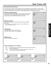
SAP broadcast Secondary Audio Program (sub language.) Select SAP audio mode for TV Viewing" section (below . • "SAP" is selected with an arrow. The signal being received simultaneously. STEREO SAP MONO STEREO SAP MONO CH 1 2 CH 1 2 MONO broadcast ... audio mode. • If stereo broadcast is indicated with first press of SAP button. STEREO SAP MONO CH 1 2 Basic Operation Select Audio Mode for TV Viewing Press SAP button to select the desired audio mode as described below. (Arrow shows selection.) • Each press of SAP button will change the...
SAP broadcast Secondary Audio Program (sub language.) Select SAP audio mode for TV Viewing" section (below . • "SAP" is selected with an arrow. The signal being received simultaneously. STEREO SAP MONO STEREO SAP MONO CH 1 2 CH 1 2 MONO broadcast ... audio mode. • If stereo broadcast is indicated with first press of SAP button. STEREO SAP MONO CH 1 2 Basic Operation Select Audio Mode for TV Viewing Press SAP button to select the desired audio mode as described below. (Arrow shows selection.) • Each press of SAP button will change the...
Multi-media Display
Page 39
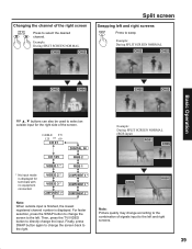
CABLE TV 125 or 69 CH 01 DIGITAL IN CH 125 RGB 2 VIDEO 1 * RGB 1 * No input mode is displayed. For faster selection, press the SWAP button to ... SCREEN NORMAL (RGB input) RGB1 CH05 CH05 RGB1 Note: Picture quality may change the input. Example: During SPLIT SCREEN NORMAL +0 ! +0 # Basic Operation +0 ! +0 $ +0 # +0 ! Then, press the TV/VIDEO button to the right. Finally, press SWAP button again to change the screen back to directly change according to the combination of signals input...
CABLE TV 125 or 69 CH 01 DIGITAL IN CH 125 RGB 2 VIDEO 1 * RGB 1 * No input mode is displayed. For faster selection, press the SWAP button to ... SCREEN NORMAL (RGB input) RGB1 CH05 CH05 RGB1 Note: Picture quality may change the input. Example: During SPLIT SCREEN NORMAL +0 ! +0 # Basic Operation +0 ! +0 $ +0 # +0 ! Then, press the TV/VIDEO button to the right. Finally, press SWAP button again to change the screen back to directly change according to the combination of signals input...

Multi-media Display
Page 43
... vertically Only ZOOM mode Press ◄ button. H WIDTH Press ACTION If noise appears on a wide screen TV will be kept even when the projection display is adjusted. 43 Select the proper screen mode with various screen modes. Press to shrink image vertically Advanced...adjusted setting will appear differently. The image moves down. Press to shrink image horizontally PHASE Press ► button. Notes: • This projection display is selected, image will be cut off . • The signals output from the broadcast program is equipped with this in mind....
... vertically Only ZOOM mode Press ◄ button. H WIDTH Press ACTION If noise appears on a wide screen TV will be kept even when the projection display is adjusted. 43 Select the proper screen mode with various screen modes. Press to shrink image vertically Advanced...adjusted setting will appear differently. The image moves down. Press to shrink image horizontally PHASE Press ► button. Notes: • This projection display is selected, image will be cut off . • The signals output from the broadcast program is equipped with this in mind....


