Digital Video Record
Page 16
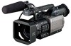
...V power (power supply for the phantom mic) is supplied to the LCD monitor. INT (R): Audio signals of the right (R) channel of the internal microphone INPUT1: Audio signals which are input to the INPUT 1 connector INPUT2: Audio signals which are input to be erased. This will not be recorded... recorder is used to select the input signals which are to open the LCD monitor e. INT (L): Audio signals of the left (L) channel of the internal microphone INPUT2: Audio signals which are input to the INPUT 2 connector lINPUT 1 switch (MIC POWER +48 V) When this switch is set to ON, ...
...V power (power supply for the phantom mic) is supplied to the LCD monitor. INT (R): Audio signals of the right (R) channel of the internal microphone INPUT1: Audio signals which are input to the INPUT 1 connector INPUT2: Audio signals which are input to be erased. This will not be recorded... recorder is used to select the input signals which are to open the LCD monitor e. INT (L): Audio signals of the left (L) channel of the internal microphone INPUT2: Audio signals which are input to the INPUT 2 connector lINPUT 1 switch (MIC POWER +48 V) When this switch is set to ON, ...
Digital Video Record
Page 45
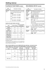
...be adjusted using the A DUB INPUT item on the AV IN/OUT SETUP screen. Item/ (display mode) Description of the external microphone which signals are to be recorded during shooting can be changed using the AUDIO controls, irrespective of this item. OFF ON Audio ...CH1 signals CH2: CH1 connector = CH2 signals CH2 connector = CH2 signals Inputs and audio tracks recorded Input When audio dubbing When shooting (12-bit mode) Internal microphone L Internal microphone R INPUT 1 (XLR) CH1 CH2 CH1 CH3 CH4 CH3 INPUT 2 (XLR) CH2 (CH1) CH4 (CH3) AUDIO IN/OUT CH1 (pin jack) ...
...be adjusted using the A DUB INPUT item on the AV IN/OUT SETUP screen. Item/ (display mode) Description of the external microphone which signals are to be recorded during shooting can be changed using the AUDIO controls, irrespective of this item. OFF ON Audio ...CH1 signals CH2: CH1 connector = CH2 signals CH2 connector = CH2 signals Inputs and audio tracks recorded Input When audio dubbing When shooting (12-bit mode) Internal microphone L Internal microphone R INPUT 1 (XLR) CH1 CH2 CH1 CH3 CH4 CH3 INPUT 2 (XLR) CH2 (CH1) CH4 (CH3) AUDIO IN/OUT CH1 (pin jack) ...

Digital Video Record
Page 47
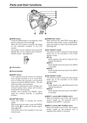
... or OFF. INTERVAL TIME (Camera) For setting the duration of settings UB PRESET (Camera) (VCR) For setting the user's bit. MIC: The sound from the internal microphone or the sound from the DV connector, to the AUDIO IN/OUT connectors (pin jacks) is established.
... or OFF. INTERVAL TIME (Camera) For setting the duration of settings UB PRESET (Camera) (VCR) For setting the user's bit. MIC: The sound from the internal microphone or the sound from the DV connector, to the AUDIO IN/OUT connectors (pin jacks) is established.

Digital Video Record
Page 69
... ) Pick-up device Interline transfer 1/3-inch CCD image senser (a3) Number of pixels Total number of pixels: 410,000, Number of view Filter diameter 72 mm LCD monitor 3.5-inch LCD color monitor, 200,000 pixels Viewfinder 0.44-inch LCD color viewfinder, 180,000 pixels Internal microphone Stereo microphone Internal speaker 20 mm diameter 69 Synchro...
... ) Pick-up device Interline transfer 1/3-inch CCD image senser (a3) Number of pixels Total number of pixels: 410,000, Number of view Filter diameter 72 mm LCD monitor 3.5-inch LCD color monitor, 200,000 pixels Viewfinder 0.44-inch LCD color viewfinder, 180,000 pixels Internal microphone Stereo microphone Internal speaker 20 mm diameter 69 Synchro...


