
Owner Manual
Page 5
...Using the Remote Controller 14 About the Remote Controller Modes 15 RECEIVER/TAPE Mode 15 DVD Mode 17 CD/MD/CDR Modes 18 DOCK Mode 19 Connecting Your Speakers 20 Enjoying Home Theater 20 Connecting Your Speakers 21 Bi-amping the Front Speakers 23 Bridging the Front Speakers (TX-SR875 only) ...RI Dock 42 Connecting the Power Cords of Other Components (North American and European models only).......42 Connecting Onkyo Components 43 Connecting the Power Cord 43 Turning On the AV Receiver 44 Turning On and Standby 44 First Time Setup 45 Speaker Settings 45 HDMI Monitor Setup 46 HDMI...
...Using the Remote Controller 14 About the Remote Controller Modes 15 RECEIVER/TAPE Mode 15 DVD Mode 17 CD/MD/CDR Modes 18 DOCK Mode 19 Connecting Your Speakers 20 Enjoying Home Theater 20 Connecting Your Speakers 21 Bi-amping the Front Speakers 23 Bridging the Front Speakers (TX-SR875 only) ...RI Dock 42 Connecting the Power Cords of Other Components (North American and European models only).......42 Connecting Onkyo Components 43 Connecting the Power Cord 43 Turning On the AV Receiver 44 Turning On and Standby 44 First Time Setup 45 Speaker Settings 45 HDMI Monitor Setup 46 HDMI...

Owner Manual
Page 6
...; Audyssey MultEQ XT room correction*10 • Easy-to-use onscreen setup menus • IR IN and OUT • Preprogrammed remote controller for use with other AV components, with Learning and Macro functions TX-SR875 Only • 140 watts minimum continuous power per channel, 8 ohm loads, 2 channels driven from 20 Hz to 20 kHz...
...; Audyssey MultEQ XT room correction*10 • Easy-to-use onscreen setup menus • IR IN and OUT • Preprogrammed remote controller for use with other AV components, with Learning and Macro functions TX-SR875 Only • 140 watts minimum continuous power per channel, 8 ohm loads, 2 channels driven from 20 Hz to 20 kHz...

Owner Manual
Page 7
...receivers also feature proprietary THX technologies (e.g., THX Mode) which is your guarantee that is a registered trademark of Niles Audio Corporation. * Apple and iPod are trademarks of Apple Computer, Inc., regis- This product incorporates copyright protection technology that the Home Theater products you purchase will give you have the following accessories: Remote... and performance tests. and other intellectual property rights. Features-Continued *5 Theater-Dimensional is a trademark of Onkyo Corporation. *6 Re-Equalization and the "Re-EQ" logo are trademarks of THX Ltd. *7 HDMI,...
...receivers also feature proprietary THX technologies (e.g., THX Mode) which is your guarantee that is a registered trademark of Niles Audio Corporation. * Apple and iPod are trademarks of Apple Computer, Inc., regis- This product incorporates copyright protection technology that the Home Theater products you purchase will give you have the following accessories: Remote... and performance tests. and other intellectual property rights. Features-Continued *5 Theater-Dimensional is a trademark of Onkyo Corporation. *6 Re-Equalization and the "Re-EQ" logo are trademarks of THX Ltd. *7 HDMI,...

Owner Manual
Page 9
...'t have this button again selects the previous listening mode. A STANDBY/ON button (44) Sets the AV receiver to -∞ dB, -81.5 dB, -81.0 dB through +18.0 dB (relative display). Lights up when this mode is being received from the remote controller. They are not shown here for clarity. E ZONE 3 indicator (105) Flashes when Zone...
...'t have this button again selects the previous listening mode. A STANDBY/ON button (44) Sets the AV receiver to -∞ dB, -81.5 dB, -81.0 dB through +18.0 dB (relative display). Lights up when this mode is being received from the remote controller. They are not shown here for clarity. E ZONE 3 indicator (105) Flashes when Zone...

Owner Manual
Page 12
...jack on another -capable Onkyo component for connecting a TV or projector with a component video input. See "Component Video Input Setup" on page 48. They're assignable, which means you must make an analog audio connection (RCA) between the AV receiver and the other component... controllers. L FM ANTENNA This jack is for remote and system control. Getting to a video input on a TV in Zone 2. K ZONE 2 OUT (TX-SR875 only) This composite video output can be connected to Know the AV Receiver-Continued Rear Panel 7 8 North American model only K TX-SR875 only 12 3 4 56 9 J LMN O...
...jack on another -capable Onkyo component for connecting a TV or projector with a component video input. See "Component Video Input Setup" on page 48. They're assignable, which means you must make an analog audio connection (RCA) between the AV receiver and the other component... controllers. L FM ANTENNA This jack is for remote and system control. Getting to a video input on a TV in Zone 2. K ZONE 2 OUT (TX-SR875 only) This composite video output can be connected to Know the AV Receiver-Continued Rear Panel 7 8 North American model only K TX-SR875 only 12 3 4 56 9 J LMN O...

Owner Manual
Page 13
...North American and European models only) These switched AC outlets can be connected to the IR OUT jack to pass IR (infrared) remote control signals through to other video source can be connected to the analog audio input on a multichannel power amplifier for ...Video and composite video input jacks for connecting a turntable's ground wire. See "Bi-amping the Front Speakers" and "Bridging the Front Speakers (TX-SR875 only)" on the AV receiver, a 12-volt trigger signal is connected here. b PRE OUT: FRONT L/R, CENTER, SUBWOOFER, SURR L/R, and SURR BACK L/R This 5.1/7.1 multichannel...
...North American and European models only) These switched AC outlets can be connected to the IR OUT jack to pass IR (infrared) remote control signals through to other video source can be connected to the analog audio input on a multichannel power amplifier for ...Video and composite video input jacks for connecting a turntable's ground wire. See "Bi-amping the Front Speakers" and "Bridging the Front Speakers (TX-SR875 only)" on the AV receiver, a 12-volt trigger signal is connected here. b PRE OUT: FRONT L/R, CENTER, SUBWOOFER, SURR L/R, and SURR BACK L/R This 5.1/7.1 multichannel...

Owner Manual
Page 14
... as soon as possible to prevent damage from leakage or corrosion. 30˚ 30˚ Approx. 16 ft. (5 m) Notes: • The remote controller may not work reliably if the AV receiver is subjected to prevent damage from leakage or corrosion. • Expired batteries should be pressed continuously, thereby draining the batteries. • The...
... as soon as possible to prevent damage from leakage or corrosion. 30˚ 30˚ Approx. 16 ft. (5 m) Notes: • The remote controller may not work reliably if the AV receiver is subjected to prevent damage from leakage or corrosion. • Expired batteries should be pressed continuously, thereby draining the batteries. • The...

Owner Manual
Page 15
...by other AV components. RECEIVER/TAPE Mode RECEIVER/TAPE mode is for use the remote controller to control your other manufacturers (see page 110 Note: Some of component. To set the remote controller to control an Onkyo cassette recorder... connected via . ■ DVD Mode By default, you can control an Onkyo DVD player in an Onkyo RI Dock that mode to control the AV receiver...
...by other AV components. RECEIVER/TAPE Mode RECEIVER/TAPE mode is for use the remote controller to control your other manufacturers (see page 110 Note: Some of component. To set the remote controller to control an Onkyo cassette recorder... connected via . ■ DVD Mode By default, you can control an Onkyo DVD player in an Onkyo RI Dock that mode to control the AV receiver...

Owner Manual
Page 16
...and ENTER buttons Used to Standby. button (67) Selects radio presets. When you press a button, the REMOTE MODE button for radio. R MUTING button (68) Mutes or unmutes the AV receiver. The Next [ ] button selects the next track. REC [ ] button Starts recording. 16 H SETUP ... Sleep function. E DIMMER button (68) Adjusts the display brightness. T L NIGHT button (81) Turns the Late Night function on the AV receiver. Remote Controller-Continued For detailed information, see the pages in parentheses. C INPUT SELECTOR buttons (62) Used to select the listening modes. B ON...
...and ENTER buttons Used to Standby. button (67) Selects radio presets. When you press a button, the REMOTE MODE button for radio. R MUTING button (68) Mutes or unmutes the AV receiver. The Next [ ] button selects the next track. REC [ ] button Starts recording. 16 H SETUP ... Sleep function. E DIMMER button (68) Adjusts the display brightness. T L NIGHT button (81) Turns the Late Night function on the AV receiver. Remote Controller-Continued For detailed information, see the pages in parentheses. C INPUT SELECTOR buttons (62) Used to select the listening modes. B ON...
Owner Manual
Page 17
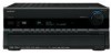
...or DTS). N MENU button Displays a DVD's menu. TUN TV VOL +10 0 CLEAR --/--- 10 11 12 INPUT SELECTOR MACRO 1 2 3 ZONE3 DVD REMOTE MODE VCR CD CDR/MD ZONE2 TV DIMMER + CH DISC ALBUM - D TOP MENU button Selects a DVD's top menu. H DISPLAY button Displays information about...track numbers, and to Standby. J REPEAT button Used with selectable play modes. PREV CH DISPLAY CABLE SAT TOP MENU DOCK MENU RECEIVER TAPE/AMP SLEEP ENTER VOL GUIDE SETUP EXIT RETURN MUTING REC PLAYLIST RANDOM STEREO LISTENING MODE SURR REPEAT AUDIO SUBTITLE PLAY MODE PURE...
...or DTS). N MENU button Displays a DVD's menu. TUN TV VOL +10 0 CLEAR --/--- 10 11 12 INPUT SELECTOR MACRO 1 2 3 ZONE3 DVD REMOTE MODE VCR CD CDR/MD ZONE2 TV DIMMER + CH DISC ALBUM - D TOP MENU button Selects a DVD's top menu. H DISPLAY button Displays information about...track numbers, and to Standby. J REPEAT button Used with selectable play modes. PREV CH DISPLAY CABLE SAT TOP MENU DOCK MENU RECEIVER TAPE/AMP SLEEP ENTER VOL GUIDE SETUP EXIT RETURN MUTING REC PLAYLIST RANDOM STEREO LISTENING MODE SURR REPEAT AUDIO SUBTITLE PLAY MODE PURE...

Owner Manual
Page 18
...ejects the MiniDisc. K CLEAR button Cancels functions and clears entered numbers. N PLAY MODE button Selects play modes. 18 Remote Controller-Continued CD/MD/CDR Modes To control an Onkyo CD player, MD recorder, or CD recorder, or a CD or MD player/recorder made by another manufacturer, you ... remote control code (see page 108). B ON button Set the component to enter track numbers and times for locating specific points. C Number buttons Used to On or Standby. I REPEAT button Used with the repeat playback function. PREV CH DISPLAY CABLE SAT TOP MENU DOCK RECEIVER...
...ejects the MiniDisc. K CLEAR button Cancels functions and clears entered numbers. N PLAY MODE button Selects play modes. 18 Remote Controller-Continued CD/MD/CDR Modes To control an Onkyo CD player, MD recorder, or CD recorder, or a CD or MD player/recorder made by another manufacturer, you ... remote control code (see page 108). B ON button Set the component to enter track numbers and times for locating specific points. C Number buttons Used to On or Standby. I REPEAT button Used with the repeat playback function. PREV CH DISPLAY CABLE SAT TOP MENU DOCK RECEIVER...

Owner Manual
Page 19
... HDD. • Set the AV receiver's Input Display to DOCK (see page 51). • See to access menus. TUN TV VOL +10 0 CLEAR --/--- 10 11 12 INPUT SELECTOR MACRO 1 2 3 ZONE3 DVD REMOTE MODE VCR CD CDR/MD ZONE2...Press it will turn on the iPod. PREV CH DISPLAY CABLE SAT TOP MENU DOCK MENU RECEIVER TAPE/AMP SLEEP ENTER VOL GUIDE SETUP EXIT RETURN MUTING REC PLAYLIST RANDOM STEREO LISTENING MODE ...selectable play modes on the backlight for controlling an Apple iPod in an Onkyo RI Dock that's connected via . C TOP MENU button Works as a Resume button when used with ...
... HDD. • Set the AV receiver's Input Display to DOCK (see page 51). • See to access menus. TUN TV VOL +10 0 CLEAR --/--- 10 11 12 INPUT SELECTOR MACRO 1 2 3 ZONE3 DVD REMOTE MODE VCR CD CDR/MD ZONE2...Press it will turn on the iPod. PREV CH DISPLAY CABLE SAT TOP MENU DOCK MENU RECEIVER TAPE/AMP SLEEP ENTER VOL GUIDE SETUP EXIT RETURN MUTING REC PLAYLIST RANDOM STEREO LISTENING MODE ...selectable play modes on the backlight for controlling an Apple iPod in an Onkyo RI Dock that's connected via . C TOP MENU button Works as a Resume button when used with ...
Owner Manual
Page 21
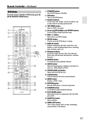
...the speaker settings. Dipole speakers TV/screen 1 2 3 4 Normal speakers TV/screen 1 2 3 4 Connecting a Powered Subwoofer Using a suitable cable, connect the AV receiver's SUBWOOFER PRE OUT to the input on them to the corresponding speaker terminal. 5 65 6 7 8 7 8 1. If your powered subwoofer. Subwoofer 2. Front ... LINE INPUT RS232 HDMI ASSIGNABLE IN 4 IN 3 IN 2 IN 1 OUT COMPONENT VIDEO ASSIGNABLE IN 3 IN 2 IN 1(DVD) MONITOR OUT Y REMOTE CB/PB CONTROL DIGITAL ASSIGNABLE COAXIAL IN 1 (DVD) CR/PR IN 2 (VCR/DVR) IN L IN OUT L AUX 1 GAME/TV CBL/SAT...
...the speaker settings. Dipole speakers TV/screen 1 2 3 4 Normal speakers TV/screen 1 2 3 4 Connecting a Powered Subwoofer Using a suitable cable, connect the AV receiver's SUBWOOFER PRE OUT to the input on them to the corresponding speaker terminal. 5 65 6 7 8 7 8 1. If your powered subwoofer. Subwoofer 2. Front ... LINE INPUT RS232 HDMI ASSIGNABLE IN 4 IN 3 IN 2 IN 1 OUT COMPONENT VIDEO ASSIGNABLE IN 3 IN 2 IN 1(DVD) MONITOR OUT Y REMOTE CB/PB CONTROL DIGITAL ASSIGNABLE COAXIAL IN 1 (DVD) CR/PR IN 2 (VCR/DVR) IN L IN OUT L AUX 1 GAME/TV CBL/SAT...
Owner Manual
Page 22
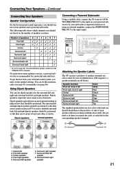
...left speaker Surround back left speaker RS232 HDMI ASSIGNABLE IN 4 IN 3 IN 2 IN 1 OUT COMPONENT VIDEO ASSIGNABLE IN 3 IN 2 IN 1(DVD) MONITOR OUT Y REMOTE CB/PB CONTROL DIGITAL ASSIGNABLE COAXIAL IN 1 (DVD) CR/PR IN 2 (VCR/DVR) IN L IN OUT L AUX 1 GAME/TV CBL/SAT V VCR/... illustration shows which speaker should be out of phase and will sound unnatural. • Unnecessarily long or very thin speaker cables may damage the AV receiver. • Don't connect a speaker to several terminals. If you get them the wrong way around, the sound will be avoided. •...
...left speaker Surround back left speaker RS232 HDMI ASSIGNABLE IN 4 IN 3 IN 2 IN 1 OUT COMPONENT VIDEO ASSIGNABLE IN 3 IN 2 IN 1(DVD) MONITOR OUT Y REMOTE CB/PB CONTROL DIGITAL ASSIGNABLE COAXIAL IN 1 (DVD) CR/PR IN 2 (VCR/DVR) IN L IN OUT L AUX 1 GAME/TV CBL/SAT V VCR/... illustration shows which speaker should be out of phase and will sound unnatural. • Unnecessarily long or very thin speaker cables may damage the AV receiver. • Don't connect a speaker to several terminals. If you get them the wrong way around, the sound will be avoided. •...
Owner Manual
Page 23
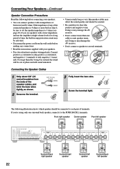
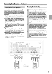
...AV receiver's SURR BACK L negative (-) terminal to the left speaker's positive (+) woofer (low) terminal. Refer to your speaker manual. • Use only front speakers with an impedance of 8 ohms or higher for a pair of front speakers that support bi-amping. RS232 IN 3 COMPONENT VIDEO ASSIGNABLE IN 3 IN 2 IN 1(DVD) MONITOR OUT Y REMOTE...the FRONT L/R terminal posts connect to the front speakers' tweeter terminals. Bi-amping Speaker Hookup 1 Connect the AV receiver's FRONT R positive (+) terminal to enable biamping (see page 45). And the SURR BACK L/R terminal posts ...
...AV receiver's SURR BACK L negative (-) terminal to the left speaker's positive (+) woofer (low) terminal. Refer to your speaker manual. • Use only front speakers with an impedance of 8 ohms or higher for a pair of front speakers that support bi-amping. RS232 IN 3 COMPONENT VIDEO ASSIGNABLE IN 3 IN 2 IN 1(DVD) MONITOR OUT Y REMOTE...the FRONT L/R terminal posts connect to the front speakers' tweeter terminals. Bi-amping Speaker Hookup 1 Connect the AV receiver's FRONT R positive (+) terminal to enable biamping (see page 45). And the SURR BACK L/R terminal posts ...

Owner Manual
Page 24
...double the output power for bridging. RS232 IN 4 IN 3 COMPONENT VIDEO ASSIGNABLE IN 3 IN 2 IN 1(DVD) MONITOR OUT Y REMOTE CB/PB CONTROL DIGITAL ASSIGNABLE COAXIAL IN 1 (DVD) CR/PR HDMI ASSIGNABLE IN 2 IN 1 OUT XM SIRIUS AUX 1 GAME/TV...'s negative terminal. 2 Connect the AV receiver's FRONT L positive (+) terminal to enable bridging (see page 45). And connect the AV receiver's SURR BACK L positive (+) terminal to the right speaker's positive (+) terminal. Connecting Your Speakers-Continued Bridging the Front Speakers (TX-SR875 only) The FRONT L/R and SURR...
...double the output power for bridging. RS232 IN 4 IN 3 COMPONENT VIDEO ASSIGNABLE IN 3 IN 2 IN 1(DVD) MONITOR OUT Y REMOTE CB/PB CONTROL DIGITAL ASSIGNABLE COAXIAL IN 1 (DVD) CR/PR HDMI ASSIGNABLE IN 2 IN 1 OUT XM SIRIUS AUX 1 GAME/TV...'s negative terminal. 2 Connect the AV receiver's FRONT L positive (+) terminal to enable bridging (see page 45). And connect the AV receiver's SURR BACK L positive (+) terminal to the right speaker's positive (+) terminal. Connecting Your Speakers-Continued Bridging the Front Speakers (TX-SR875 only) The FRONT L/R and SURR...

Owner Manual
Page 30
...b or c . (To record or listen in Zone 2 or Zone 3 as well, use its tuner to listen to the AV receiver and use a and b , or a and c .) Connection A B C a b c AV receiver COMPONENT VIDEO MONITOR OUT MONITOR OUT S MONITOR OUT V GAME/TV IN L/R DIGITAL COAXIAL IN 2 DIGITAL OPTICAL IN 2 Signal &#... output Digital coaxial output Digital optical output Picture quality Best Better Standard b c A RS232 COMPONENT VIDEO ASSIGNABLE IN 3 IN 2 IN 1(DVD) MONITOR OUT Y REMOTE CB/PB CONTROL DIGITAL ASSIGNABLE COAXIAL IN 1 (DVD) CR/PR IN 2 (VCR/DVR) IN L IN OUT L AUX 1 GAME/TV CBL/SAT V...
...b or c . (To record or listen in Zone 2 or Zone 3 as well, use its tuner to listen to the AV receiver and use a and b , or a and c .) Connection A B C a b c AV receiver COMPONENT VIDEO MONITOR OUT MONITOR OUT S MONITOR OUT V GAME/TV IN L/R DIGITAL COAXIAL IN 2 DIGITAL OPTICAL IN 2 Signal &#... output Digital coaxial output Digital optical output Picture quality Best Better Standard b c A RS232 COMPONENT VIDEO ASSIGNABLE IN 3 IN 2 IN 1(DVD) MONITOR OUT Y REMOTE CB/PB CONTROL DIGITAL ASSIGNABLE COAXIAL IN 1 (DVD) CR/PR IN 2 (VCR/DVR) IN L IN OUT L AUX 1 GAME/TV CBL/SAT V...
Owner Manual
Page 31
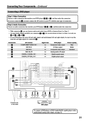
...A , B , or C ), and then make the connection. • With connection a , you must connect the AV receiver to your TV with a multichannel analog audio output, see page 32. 31 Connection A B C a b c AV receiver COMPONENT VIDEO IN 1 DVD IN S DVD IN V DVD IN L/R DIGITAL COAXIAL IN 1 DIGITAL OPTICAL IN 1 Signal ... coaxial output Digital optical output Picture quality Best Better Standard b c A RS232 COMPONENT VIDEO ASSIGNABLE IN 3 IN 2 IN 1(DVD) MONITOR OUT Y REMOTE CB/PB CONTROL DIGITAL ASSIGNABLE COAXIAL IN 1 (DVD) CR/PR IN 2 (VCR/DVR) IN L IN OUT L AUX 1 GAME/TV CBL...
...A , B , or C ), and then make the connection. • With connection a , you must connect the AV receiver to your TV with a multichannel analog audio output, see page 32. 31 Connection A B C a b c AV receiver COMPONENT VIDEO IN 1 DVD IN S DVD IN V DVD IN L/R DIGITAL COAXIAL IN 1 DIGITAL OPTICAL IN 1 Signal ... coaxial output Digital optical output Picture quality Best Better Standard b c A RS232 COMPONENT VIDEO ASSIGNABLE IN 3 IN 2 IN 1(DVD) MONITOR OUT Y REMOTE CB/PB CONTROL DIGITAL ASSIGNABLE COAXIAL IN 1 (DVD) CR/PR IN 2 (VCR/DVR) IN L IN OUT L AUX 1 GAME/TV CBL...

Owner Manual
Page 32
...analog audio output on page 99. RS232 HDMI ASSIGNABLE IN 3 IN 2 IN 1 OUT COMPONENT VIDEO ASSIGNABLE IN 3 IN 2 IN 1(DVD) MONITOR OUT Y REMOTE CB/PB CONTROL DIGITAL ASSIGNABLE COAXIAL IN 1 (DVD) CR/PR IN 2 (VCR/DVR) IN L IN OUT L AUX 1 GAME/TV CBL/SAT V ...RL R FRONT CENTER SUB WOOFER SURROUND SURR BACK DVD player 32 Use a multichannel analog audio cable, or several normal audio cables, to connect the AV receiver's MULTI CH FRONT L/R, CENTER, SURR L/R, SURR BACK L/R, and SUBWOOFER jacks to an input selector. To select the multichannel input, see "Subwoofer ...
...analog audio output on page 99. RS232 HDMI ASSIGNABLE IN 3 IN 2 IN 1 OUT COMPONENT VIDEO ASSIGNABLE IN 3 IN 2 IN 1(DVD) MONITOR OUT Y REMOTE CB/PB CONTROL DIGITAL ASSIGNABLE COAXIAL IN 1 (DVD) CR/PR IN 2 (VCR/DVR) IN L IN OUT L AUX 1 GAME/TV CBL/SAT V ...RL R FRONT CENTER SUB WOOFER SURROUND SURR BACK DVD player 32 Use a multichannel analog audio cable, or several normal audio cables, to connect the AV receiver's MULTI CH FRONT L/R, CENTER, SURR L/R, SURR BACK L/R, and SUBWOOFER jacks to an input selector. To select the multichannel input, see "Subwoofer ...

Owner Manual
Page 33
...a , you can use the tuner in Zone 2 or Zone 3 as well, use connection A , you use a and b , or a and c .) Connection A B C a b c AV receiver COMPONENT VIDEO IN 2 VCR/DVR IN S VCR/DVR IN V VCR/DVR IN L/R DIGITAL COAXIAL IN 2 DIGITAL OPTICAL IN 1 Signal flow VCR or DVR Component... L/R output Digital coaxial output Digital optical output Picture quality Best Better Standard b c A COMPONENT VIDEO ASSIGNABLE IN 3 IN 2 IN 1(DVD) MONITOR OUT Y REMOTE CB/PB CONTROL DIGITAL ASSIGNABLE COAXIAL IN 1 (DVD) CR/PR IN 2 (VCR/DVR) IN L IN OUT L AUX 1 GAME/TV CBL/SAT V ...
...a , you can use the tuner in Zone 2 or Zone 3 as well, use connection A , you use a and b , or a and c .) Connection A B C a b c AV receiver COMPONENT VIDEO IN 2 VCR/DVR IN S VCR/DVR IN V VCR/DVR IN L/R DIGITAL COAXIAL IN 2 DIGITAL OPTICAL IN 1 Signal flow VCR or DVR Component... L/R output Digital coaxial output Digital optical output Picture quality Best Better Standard b c A COMPONENT VIDEO ASSIGNABLE IN 3 IN 2 IN 1(DVD) MONITOR OUT Y REMOTE CB/PB CONTROL DIGITAL ASSIGNABLE COAXIAL IN 1 (DVD) CR/PR IN 2 (VCR/DVR) IN L IN OUT L AUX 1 GAME/TV CBL/SAT V ...


