
Owner Manual
Page 2
... exclamation point within an equilateral triangle, is damaged, liquid has been spilled or objects have fallen into the apparatus through openings as vases shall be set 10 cm (4") away from tip-over. PORTABLE CART WARNING S3125A 13. CAUTION: TO REDUCE THE RISK OF ELECTRIC SHOCK, DO NOT REMOVE COVER (OR BACK...
... exclamation point within an equilateral triangle, is damaged, liquid has been spilled or objects have fallen into the apparatus through openings as vases shall be set 10 cm (4") away from tip-over. PORTABLE CART WARNING S3125A 13. CAUTION: TO REDUCE THE RISK OF ELECTRIC SHOCK, DO NOT REMOVE COVER (OR BACK...

Owner Manual
Page 5
...TX-SR875 only) ....24 Connecting Antennas 25 Connecting the Indoor FM Antenna 25 Connecting the AM Loop Antenna 25 Connecting an Outdoor FM Antenna 26 Connecting an Outdoor AM Antenna 26 Connecting Your Components 27 About AV Connections 27 Connecting Audio and Video Signals to the AV Receiver...of Other Components (North American and European models only).......42 Connecting Onkyo Components 43 Connecting the Power Cord 43 Turning On the AV Receiver 44 Turning On and Standby 44 First Time Setup 45 Speaker Settings 45 HDMI Monitor Setup 46 HDMI Input Setup 48 Component Video Input...
...TX-SR875 only) ....24 Connecting Antennas 25 Connecting the Indoor FM Antenna 25 Connecting the AM Loop Antenna 25 Connecting an Outdoor FM Antenna 26 Connecting an Outdoor AM Antenna 26 Connecting Your Components 27 About AV Connections 27 Connecting Audio and Video Signals to the AV Receiver...of Other Components (North American and European models only).......42 Connecting Onkyo Components 43 Connecting the Power Cord 43 Turning On the AV Receiver 44 Turning On and Standby 44 First Time Setup 45 Speaker Settings 45 HDMI Monitor Setup 46 HDMI Input Setup 48 Component Video Input...

Owner Manual
Page 9
...the following input sources: DVD, VCR/DVR, CBL/SAT, GAME/TV, AUX 1, AUX 2, TAPE, TUNER, CD, PHONO. 9 A STANDBY/ON button (44) Sets the AV receiver to -∞ dB, -81.5 dB, -81.0 dB through +18.0 dB (relative display). B STANDBY indicator (44) Lights up when Zone 3 is on... when Zone 3 is being set . I MASTER VOLUME control (62) Sets the volume of the AV receiver to On or Standby. F Remote-control sensor (14) Receives control signals from the remote controller. D ZONE 2 indicator (105) Flashes when Zone 2 is being set . Lights up when the AV receiver is on . They are not...
...the following input sources: DVD, VCR/DVR, CBL/SAT, GAME/TV, AUX 1, AUX 2, TAPE, TUNER, CD, PHONO. 9 A STANDBY/ON button (44) Sets the AV receiver to -∞ dB, -81.5 dB, -81.0 dB through +18.0 dB (relative display). B STANDBY indicator (44) Lights up when Zone 3 is on... when Zone 3 is being set . I MASTER VOLUME control (62) Sets the volume of the AV receiver to On or Standby. F Remote-control sensor (14) Receives control signals from the remote controller. D ZONE 2 indicator (105) Flashes when Zone 2 is being set . Lights up when the AV receiver is on . They are not...

Owner Manual
Page 10
... standard pair of stereo headphones for AM and FM radio. W SETUP button Opens and closes the onscreen setup menus, which are used to Know the AV Receiver-Continued North American model M N OP Q RS TUV W X Y PHONES ZONE 2 OFF LEVEL TONE HDMI OUT STEREO THX TUNING DIMMER MEMORY MODE ...Zone 3. N ZONE 2, ZONE 3, and OFF buttons (105) The ZONE 2 button is used with RDS (Radio Data System). The OFF button is used when setting Zone 3. U MEMORY button (67) Used when storing or deleting radio presets. Z SETUP MIC (55) The automatic speaker setup microphone connects here. P TONE ...
... standard pair of stereo headphones for AM and FM radio. W SETUP button Opens and closes the onscreen setup menus, which are used to Know the AV Receiver-Continued North American model M N OP Q RS TUV W X Y PHONES ZONE 2 OFF LEVEL TONE HDMI OUT STEREO THX TUNING DIMMER MEMORY MODE ...Zone 3. N ZONE 2, ZONE 3, and OFF buttons (105) The ZONE 2 button is used with RDS (Radio Data System). The OFF button is used when setting Zone 3. U MEMORY button (67) Used when storing or deleting radio presets. Z SETUP MIC (55) The automatic speaker setup microphone connects here. P TONE ...

Owner Manual
Page 11
... right - SBR: Surround back right 2 BTL indicator (45) (TX-SR875 only) Lights up when the Speaker Type setting is set to BTL for AM or FM radio. d LISTENING MODE [ ]/[ ] buttons (71) Select the Onkyo original listening modes. When set the AV receiver to No or None. Display 1 23 4 56 7 8 9...Lights up when tuned to input selectors. B MUTING indicator (68) Flashes while the AV receiver is selected for bridged front speaker operation. 3 ZONE 2 indicator (105) Lights up when tuned to a radio station that 's set to On or Standby. C: Center - TUNED (63): Lights up when Auto Tuning...
... right - SBR: Surround back right 2 BTL indicator (45) (TX-SR875 only) Lights up when the Speaker Type setting is set to BTL for AM or FM radio. d LISTENING MODE [ ]/[ ] buttons (71) Select the Onkyo original listening modes. When set the AV receiver to No or None. Display 1 23 4 56 7 8 9...Lights up when tuned to input selectors. B MUTING indicator (68) Flashes while the AV receiver is selected for bridged front speaker operation. 3 ZONE 2 indicator (105) Lights up when tuned to a radio station that 's set to On or Standby. C: Center - TUNED (63): Lights up when Auto Tuning...

Owner Manual
Page 15
... can also be used to select a mode. 2 Use the buttons supported by using the REMOTE MODE buttons. ■ RECEIVER/TAPE Mode In RECEIVER/TAPE mode, you can control the AV receiver and an Onkyo cassette recorder connected via . ■ DVD Mode By default, you can control a cable or satellite TV... components made by other manufacturers (see page 108). ■ DOCK Mode This mode is used to control the component. To set the remote controller to control your other AV components. TUN TV VOL +10 0 CLEAR --/--- 10 11 12 INPUT SELECTOR MACRO 1 2 3 ZONE3 DVD REMOTE MODE VCR...
... can also be used to select a mode. 2 Use the buttons supported by using the REMOTE MODE buttons. ■ RECEIVER/TAPE Mode In RECEIVER/TAPE mode, you can control the AV receiver and an Onkyo cassette recorder connected via . ■ DVD Mode By default, you can control a cable or satellite TV... components made by other manufacturers (see page 108). ■ DOCK Mode This mode is used to control the component. To set the remote controller to control your other AV components. TUN TV VOL +10 0 CLEAR --/--- 10 11 12 INPUT SELECTOR MACRO 1 2 3 ZONE3 DVD REMOTE MODE VCR...

Owner Manual
Page 16
...B ON button (44) Turns on or off. D MACRO buttons (112) Used with the Macro function. A STANDBY button (44) Sets the AV receiver to select and adjust settings. F Arrow and ENTER buttons Used to Standby. I DISPLAY button (69) Displays information about the current input source. When you press a...and Fast Forward [ ]/[ ] buttons The Rewind [ ] button starts rewind. Q RETURN button Returns to change settings. T L NIGHT button (81) Turns the Late Night function on the AV receiver. N REMOTE MODE buttons (15) Used to adjust the level of the current track. Remote Controller-Continued For...
...B ON button (44) Turns on or off. D MACRO buttons (112) Used with the Macro function. A STANDBY button (44) Sets the AV receiver to select and adjust settings. F Arrow and ENTER buttons Used to Standby. I DISPLAY button (69) Displays information about the current input source. When you press a...and Fast Forward [ ]/[ ] buttons The Rewind [ ] button starts rewind. Q RETURN button Returns to change settings. T L NIGHT button (81) Turns the Late Night function on the AV receiver. N REMOTE MODE buttons (15) Used to adjust the level of the current track. Remote Controller-Continued For...
Owner Manual
Page 17
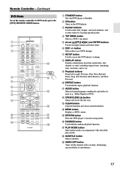
... MODE VCR CD CDR/MD ZONE2 TV DIMMER + CH DISC ALBUM - PREV CH DISPLAY CABLE SAT TOP MENU DOCK MENU RECEIVER TAPE/AMP SLEEP ENTER VOL GUIDE SETUP EXIT RETURN MUTING REC PLAYLIST RANDOM STEREO LISTENING MODE SURR REPEAT AUDIO SUBTITLE PLAY MODE ...button Selects a DVD's top menu. K AUDIO button Selects foreign language soundtracks and audio formats (e.g., Dolby Digital or DTS). Remote Controller-Continued DVD Mode To set the remote controller to right: Previous, Play, Next, Rewind, Pause, Stop, Fast Forward, Slow Reverse, and Slow Forward. TAPE TUNER CD 7 8 ...
... MODE VCR CD CDR/MD ZONE2 TV DIMMER + CH DISC ALBUM - PREV CH DISPLAY CABLE SAT TOP MENU DOCK MENU RECEIVER TAPE/AMP SLEEP ENTER VOL GUIDE SETUP EXIT RETURN MUTING REC PLAYLIST RANDOM STEREO LISTENING MODE SURR REPEAT AUDIO SUBTITLE PLAY MODE ...button Selects a DVD's top menu. K AUDIO button Selects foreign language soundtracks and audio formats (e.g., Dolby Digital or DTS). Remote Controller-Continued DVD Mode To set the remote controller to right: Previous, Play, Next, Rewind, Pause, Stop, Fast Forward, Slow Reverse, and Slow Forward. TAPE TUNER CD 7 8 ...

Owner Manual
Page 18
PREV CH DISPLAY CABLE SAT TOP MENU DOCK RECEIVER TAPE/AMP SLEEP MENU ENTER VOL GUIDE SETUP EXIT ...button Opens or closes the disc tray or ejects the MiniDisc. K CLEAR button Cancels functions and clears entered numbers. B ON button Set the component to right: Previous, Play, Next, Rewind, Pause, Stop, and Fast Forward. G Playback buttons From left to On...playback function. TAPE TUNER CD 7 8 9 PHONO D. Remote Controller-Continued CD/MD/CDR Modes To control an Onkyo CD player, MD recorder, or CD recorder, or a CD or MD player/recorder made by another manufacturer,...
PREV CH DISPLAY CABLE SAT TOP MENU DOCK RECEIVER TAPE/AMP SLEEP MENU ENTER VOL GUIDE SETUP EXIT ...button Opens or closes the disc tray or ejects the MiniDisc. K CLEAR button Cancels functions and clears entered numbers. B ON button Set the component to right: Previous, Play, Next, Rewind, Pause, Stop, and Fast Forward. G Playback buttons From left to On...playback function. TAPE TUNER CD 7 8 9 PHONO D. Remote Controller-Continued CD/MD/CDR Modes To control an Onkyo CD player, MD recorder, or CD recorder, or a CD or MD player/recorder made by another manufacturer,...

Owner Manual
Page 19
... 6 + TV CH - D Arrow [ ]/[ ] and ENTER buttons* Used to select the previous or next playlist on the backlight for controlling an Apple iPod in an Onkyo RI Dock that's connected via . F DISPLAY button* Turns on the iPod. button* Selects the next or previous album. H Pause [ ] button Pauses playback. (With ... Using an RI Dock: • Connect the RI Dock to the TAPE IN or GAME/TV IN L/R jacks. • Set the RI Dock's RI MODE switch to HDD. • Set the AV receiver's Input Display to DOCK (see page 51). • See to select the previous song. TAPE TUNER CD 7 8 9 PHONO...
... 6 + TV CH - D Arrow [ ]/[ ] and ENTER buttons* Used to select the previous or next playlist on the backlight for controlling an Apple iPod in an Onkyo RI Dock that's connected via . F DISPLAY button* Turns on the iPod. button* Selects the next or previous album. H Pause [ ] button Pauses playback. (With ... Using an RI Dock: • Connect the RI Dock to the TAPE IN or GAME/TV IN L/R jacks. • Set the RI Dock's RI MODE switch to HDD. • Set the AV receiver's Input Display to DOCK (see page 51). • See to select the previous song. TAPE TUNER CD 7 8 9 PHONO...
Owner Manual
Page 21
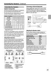
...screen, while the surround back left and right dipolar speakers should connect seven speakers and a powered subwoofer. All you must set the speaker settings. Subwoofer 2. Front right speaker 5. No matter how many speakers you 're using an external amplifier, connect ... . Dipole speakers TV/screen 1 2 3 4 Normal speakers TV/screen 1 2 3 4 Connecting a Powered Subwoofer Using a suitable cable, connect the AV receiver's SUBWOOFER PRE OUT to the input on them to the positive (+) side of each speaker cable in two directions. Using Dipole Speakers You can do...
...screen, while the surround back left and right dipolar speakers should connect seven speakers and a powered subwoofer. All you must set the speaker settings. Subwoofer 2. Front right speaker 5. No matter how many speakers you 're using an external amplifier, connect ... . Dipole speakers TV/screen 1 2 3 4 Normal speakers TV/screen 1 2 3 4 Connecting a Powered Subwoofer Using a suitable cable, connect the AV receiver's SUBWOOFER PRE OUT to the input on them to the positive (+) side of each speaker cable in two directions. Using Dipole Speakers You can do...
Owner Manual
Page 22
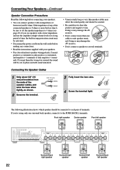
... Read the following illustration shows which speaker should be avoided. • Be careful not to speaker wiring polarity. Doing so may damage the AV receiver. • Don't connect more but less than one surround back speaker, connect it to the SURR BACK L terminals. Front right speaker ...speaker terminal. If you 're using only one cable to several terminals. Doing so may affect the sound quality and should be sure to set the speaker impedance to only negative (-) terminals. Connecting the Speaker Cables 1 Strip about 5/8" (15 mm) of insulation from the wall outlet...
... Read the following illustration shows which speaker should be avoided. • Be careful not to speaker wiring polarity. Doing so may damage the AV receiver. • Don't connect more but less than one surround back speaker, connect it to the SURR BACK L terminals. Front right speaker ...speaker terminal. If you 're using only one cable to several terminals. Doing so may affect the sound quality and should be sure to set the speaker impedance to only negative (-) terminals. Connecting the Speaker Cables 1 Strip about 5/8" (15 mm) of insulation from the wall outlet...
Owner Manual
Page 23
... posts connect to the front speakers' woofer terminals. • Once you've completed the bi-amping connections shown below and turned on the AV receiver, you must set the Speaker Type setting to Bi-Amp to the left speaker's positive (+) tweeter (high) terminal. Refer to your speaker manual. • Use only front speakers with...
... posts connect to the front speakers' woofer terminals. • Once you've completed the bi-amping connections shown below and turned on the AV receiver, you must set the Speaker Type setting to Bi-Amp to the left speaker's positive (+) tweeter (high) terminal. Refer to your speaker manual. • Use only front speakers with...

Owner Manual
Page 24
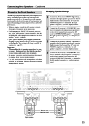
...the bridging connections shown below and turned on the AV receiver, you must set the Speaker Type setting to BTL to the left speaker's negative terminal. Bridged Speaker Hookup 1 Connect the AV receiver's FRONT R positive (+) terminal to provide almost ...double the output power for bridging. Notes: • Use only front speakers with front speakers and surround back speakers respectively, or bridged together to the right speaker's positive (+) terminal. Connecting Your Speakers-Continued Bridging the Front Speakers (TX...
...the bridging connections shown below and turned on the AV receiver, you must set the Speaker Type setting to BTL to the left speaker's negative terminal. Bridged Speaker Hookup 1 Connect the AV receiver's FRONT R positive (+) terminal to provide almost ...double the output power for bridging. Notes: • Use only front speakers with front speakers and surround back speakers respectively, or bridged together to the right speaker's positive (+) terminal. Connecting Your Speakers-Continued Bridging the Front Speakers (TX...

Owner Manual
Page 28
...Signal Flow Chart DVD player, etc. For video components, you set the Immediate Display preference to Off (page 97). ■ HDMI Monitor Setting Set to Yes With the HDMI Monitor setting set to the AV receiver by using any one of AV equipment. It's also recommended that video signals pass through the..., S-Video, component video, or HDMI, the latter offering the best picture quality. Use this setting if you connect the AV receiver's HDMI OUT to your other AV components to the AV receiver, you choose will depend on the formats supported by changing the input source on the HDMI Monitor...
...Signal Flow Chart DVD player, etc. For video components, you set the Immediate Display preference to Off (page 97). ■ HDMI Monitor Setting Set to Yes With the HDMI Monitor setting set to the AV receiver by using any one of AV equipment. It's also recommended that video signals pass through the..., S-Video, component video, or HDMI, the latter offering the best picture quality. Use this setting if you connect the AV receiver's HDMI OUT to your other AV components to the AV receiver, you choose will depend on the formats supported by changing the input source on the HDMI Monitor...

Owner Manual
Page 29
...pass through their respective input signals as they are not output. Note that the AV receiver does not convert digital input signals for the component video output. On the TX-SR875, this setting if you connect the AV receiver's COMPONENT VIDEO OUT to your TV. Use this signal flow also ...applies when the Monitor Out Resolution setting is set to anything other than Through (see page 46), if the...
...pass through their respective input signals as they are not output. Note that the AV receiver does not convert digital input signals for the component video output. On the TX-SR875, this setting if you connect the AV receiver's COMPONENT VIDEO OUT to your TV. Use this signal flow also ...applies when the Monitor Out Resolution setting is set to anything other than Through (see page 46), if the...

Owner Manual
Page 35
... ( A , B , or C ), and then make the connection. • With connection a , you can use a and b , or a and c .) Connection A B C a b c AV receiver COMPONENT VIDEO 3 IN CBL/SAT IN S CBL/SAT IN V CBL/SAT IN L/R DIGITAL COAXIAL IN 3 DIGITAL OPTICAL IN 2 Signal flow Video source Component video...COMPONENT VIDEO OUT L R AUDIO OUT S VIDEO OUT VIDEO OUT Satellite, cable, set-top box, etc. 35 With this hookup, you must connect the AV receiver to your favorite TV programs via the AV receiver, which is useful if your TV with the same type of connection. Connecting Your...
... ( A , B , or C ), and then make the connection. • With connection a , you can use a and b , or a and c .) Connection A B C a b c AV receiver COMPONENT VIDEO 3 IN CBL/SAT IN S CBL/SAT IN V CBL/SAT IN L/R DIGITAL COAXIAL IN 3 DIGITAL OPTICAL IN 2 Signal flow Video source Component video...COMPONENT VIDEO OUT L R AUDIO OUT S VIDEO OUT VIDEO OUT Satellite, cable, set-top box, etc. 35 With this hookup, you must connect the AV receiver to your favorite TV programs via the AV receiver, which is useful if your TV with the same type of connection. Connecting Your...

Owner Manual
Page 36
...audio, or multichannel PCM). About Copyright Protection The AV receiver supports HDCP (High-bandwidth Digital Content Protection),*2 a copy-protection system for connecting TVs, projectors, DVD players, set by the DDWG*3 in no picture.) The AV receiver uses HDCP (High-bandwidth Digital Content Protection), ... Content Protection): The video encryption technology developed by Intel for high-performance PCs and digital displays. 36 The AV receiver's HDMI interface is to the AV receiver via HDMI must be connected by Intel, Compaq, Fujitsu, Hewlett Packard, IBM, NEC, and Silicon Image,...
...audio, or multichannel PCM). About Copyright Protection The AV receiver supports HDCP (High-bandwidth Digital Content Protection),*2 a copy-protection system for connecting TVs, projectors, DVD players, set by the DDWG*3 in no picture.) The AV receiver uses HDCP (High-bandwidth Digital Content Protection), ... Content Protection): The video encryption technology developed by Intel for high-performance PCs and digital displays. 36 The AV receiver's HDMI interface is to the AV receiver via HDMI must be connected by Intel, Compaq, Fujitsu, Hewlett Packard, IBM, NEC, and Silicon Image,...

Owner Manual
Page 37
... or TV Control is selected, the AV receiver's speakers may produce no sound or the sound may be upconverted for the HDMI output. To stop the AV receiver's speakers producing sound, change the settings, change your TV's settings, or turn up the AV receiver's volume control, the sound will be ...seen on your TV (e.g., on or a different input is set to Enable and you turn down the AV receiver's volume. Step 2: Assign...
... or TV Control is selected, the AV receiver's speakers may produce no sound or the sound may be upconverted for the HDMI output. To stop the AV receiver's speakers producing sound, change the settings, change your TV's settings, or turn up the AV receiver's volume control, the sound will be ...seen on your TV (e.g., on or a different input is set to Enable and you turn down the AV receiver's volume. Step 2: Assign...
Owner Manual
Page 42
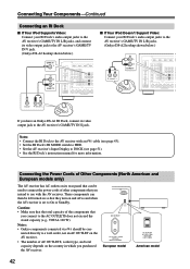
...OUTLETS, socket type, and total capacity depends on its rear panel that they turn on and off as and when the AV receiver is set to On or Standby. Notes: • Onkyo components connected via should be left turned on so that can then be con- AC OUTLET AC 220-240V 50/60Hz SWITCHED...'s RI MODE switch to HDD. • Set the AV receiver's Input Display to DOCK (see page 51). • See the RI Dock's instruction manual for more information. American model 42 Caution: • Make sure that the total capacity of other components that you have an Onkyo DS-A1 RI Dock, connect its video...
...OUTLETS, socket type, and total capacity depends on its rear panel that they turn on and off as and when the AV receiver is set to On or Standby. Notes: • Onkyo components connected via should be left turned on so that can then be con- AC OUTLET AC 220-240V 50/60Hz SWITCHED...'s RI MODE switch to HDD. • Set the AV receiver's Input Display to DOCK (see page 51). • See the RI Dock's instruction manual for more information. American model 42 Caution: • Make sure that the total capacity of other components that you have an Onkyo DS-A1 RI Dock, connect its video...


