Owner Manual
Page 1
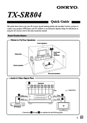
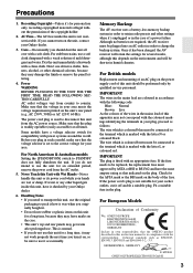
TX-SR804 Quick Guide This guide shows how to use Automatic Speaker Setup. It shows you how to connect your speakers, DVD player, and TV, and how to get your AV receiver up and running quickly and smoothly. For full details on the following pages. 1 En Home Theater Basics ❍ Where to Put Your Speakers... ❍ Audio & Video Signal Flow 1 Speakers Surround speakers 2 Video 3 Audio Audio Video 4 Audio 5 : Signal Flow DVD player TV Connections 1 through 5 are explained on using the AV receiver, refer to the main instruction manual.
TX-SR804 Quick Guide This guide shows how to use Automatic Speaker Setup. It shows you how to connect your speakers, DVD player, and TV, and how to get your AV receiver up and running quickly and smoothly. For full details on the following pages. 1 En Home Theater Basics ❍ Where to Put Your Speakers... ❍ Audio & Video Signal Flow 1 Speakers Surround speakers 2 Video 3 Audio Audio Video 4 Audio 5 : Signal Flow DVD player TV Connections 1 through 5 are explained on using the AV receiver, refer to the main instruction manual.
Owner Manual
Page 2
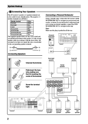
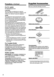
...Center White Red Green Surround left Surround right Blue Gray Surround back left speaker 2 Connecting a Powered Subwoofer Using a suitable cable, connect the AV receiver's SUBWOOFER PRE OUT to an input on your subwoofer is to match the color of the terminal. 3 Screw the terminal tight. All you...using an external amplifier, connect the SUBWOOFER PRE OUT to an input on the amp. System Hookup 1 Connecting Your Speakers The AV receiver's positive (+) speaker terminals are color-coded for easy identification. (The negative (-) speaker terminals are also color-coded and you ...
...Center White Red Green Surround left Surround right Blue Gray Surround back left speaker 2 Connecting a Powered Subwoofer Using a suitable cable, connect the AV receiver's SUBWOOFER PRE OUT to an input on your subwoofer is to match the color of the terminal. 3 Screw the terminal tight. All you...using an external amplifier, connect the SUBWOOFER PRE OUT to an input on the amp. System Hookup 1 Connecting Your Speakers The AV receiver's positive (+) speaker terminals are color-coded for easy identification. (The negative (-) speaker terminals are also color-coded and you ...

Owner Manual
Page 3
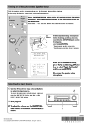
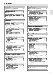
IN1 XIAL COAXIAL OUT DVD player 3 VIDEO OUT DVD IN V 2 FRONT L R DVD Connection 2 3 3 AV receiver DVD IN V DVD IN FRONT DIGITAL COAXIAL IN 1 Signal flow DVD player Composite video output Analog audio L/R output Digital coaxial output Note... modes, the analog connection 3 allows you to listen in Zone 2. 4+5 Basic TV Hookup 5 L R AUDIO OUT IN L R VIDEO 3 TV VIDEO IN MONITOR OUT V 4 Connection 4 5 AV receiver MONITOR OUT V VIDEO 3 IN L/R Signal flow TV Composite video input Analog audio L/R output Note: Connection 5 is only necessary if you want to listen to...
IN1 XIAL COAXIAL OUT DVD player 3 VIDEO OUT DVD IN V 2 FRONT L R DVD Connection 2 3 3 AV receiver DVD IN V DVD IN FRONT DIGITAL COAXIAL IN 1 Signal flow DVD player Composite video output Analog audio L/R output Digital coaxial output Note... modes, the analog connection 3 allows you to listen in Zone 2. 4+5 Basic TV Hookup 5 L R AUDIO OUT IN L R VIDEO 3 TV VIDEO IN MONITOR OUT V 4 Connection 4 5 AV receiver MONITOR OUT V VIDEO 3 IN L/R Signal flow TV Composite video input Analog audio L/R output Note: Connection 5 is only necessary if you want to listen to...
Owner Manual
Page 4
...Loud sound. Selecting the Input Source 1. UME control, or the remote controller's [VOL] button. Use the AV receiver's input selector buttons to turn on the AV receiver. To select the input source with Test noise Level up Cancel When you've finished the setup, ... all your speakers. 1 Remote controller AV receiver STANDBY/ON RECEIVER or ON Press the [STANDBY/ON] button on the AV receiver or press the remote controller's [RECEIVER] button followed by the [ON] button to select the input source. SN 29344330 (C) Copyright 2006 ONKYO CORPORATION Japan. All rights reserved. 3...
...Loud sound. Selecting the Input Source 1. UME control, or the remote controller's [VOL] button. Use the AV receiver's input selector buttons to turn on the AV receiver. To select the input source with Test noise Level up Cancel When you've finished the setup, ... all your speakers. 1 Remote controller AV receiver STANDBY/ON RECEIVER or ON Press the [STANDBY/ON] button on the AV receiver or press the remote controller's [RECEIVER] button followed by the [ON] button to select the input source. SN 29344330 (C) Copyright 2006 ONKYO CORPORATION Japan. All rights reserved. 3...
Instruction Manual
Page 1
... Troubleshooting 91 En Following the instructions in the unit. Please read this manual thoroughly before making connections and plugging in this manual for purchasing an Onkyo AV Receiver. AV Receiver TX-SR804 TX-SR804E Contents Introduction 2 Connection 19 Turning On & First Time Setup..... 39 Instruction Manual Basic Operation Playing your new...
... Troubleshooting 91 En Following the instructions in the unit. Please read this manual thoroughly before making connections and plugging in this manual for purchasing an Onkyo AV Receiver. AV Receiver TX-SR804 TX-SR804E Contents Introduction 2 Connection 19 Turning On & First Time Setup..... 39 Instruction Manual Basic Operation Playing your new...
Instruction Manual
Page 3
... AC outlet. 5. Don't use a soft cloth dampened with power systems around the world. Some models have it has been charged, the AV receiver will retain the settings for several weeks, although this depends on the environment and will be sure to charge the backup system. This is ...must be plugged into an AC outlet in your socket outlets, cut it occasionally. Once it checked by qualified service personnel. MIYAGI ONKYO EUROPE ELECTRONICS GmbH 3 Never Touch this Unit with the letter L or coloured red. Dry the unit immediately afterwards with a soft cloth. ...
... AC outlet. 5. Don't use a soft cloth dampened with power systems around the world. Some models have it has been charged, the AV receiver will retain the settings for several weeks, although this depends on the environment and will be sure to charge the backup system. This is ...must be plugged into an AC outlet in your socket outlets, cut it occasionally. Once it checked by qualified service personnel. MIYAGI ONKYO EUROPE ELECTRONICS GmbH 3 Never Touch this Unit with the letter L or coloured red. Dry the unit immediately afterwards with a soft cloth. ...
Instruction Manual
Page 4
...indicates the color. For models having a power cord with the instructions, may cause harmful interference to radio or television reception, which the receiver is connected. • Consult the dealer or an experienced radio/TV techni- Front Left Front Left SP-B / Zone 2 Left SP...Make sure you have the following measures: • Reorient or relocate the receiving antenna. • Increase the separation between the equipment and receiver. • Connect the equipment into an outlet on the AV receiver's power cord. (Adapter varies from that interference will not occur in accordance ...
...indicates the color. For models having a power cord with the instructions, may cause harmful interference to radio or television reception, which the receiver is connected. • Consult the dealer or an experienced radio/TV techni- Front Left Front Left SP-B / Zone 2 Left SP...Make sure you have the following measures: • Reorient or relocate the receiving antenna. • Increase the separation between the equipment and receiver. • Connect the equipment into an outlet on the AV receiver's power cord. (Adapter varies from that interference will not occur in accordance ...

Instruction Manual
Page 6
Zone 2: In your sub room, you can enjoy 2-channel stereo playback (pages 82-84). *The listening modes cannot be used with this AV receiver-a surround-sound speaker system (up to 7.1 channels) in your sub room, or Zone 2, as Dolby, DTS, and THX (pages 60-63). *If the Powered Zone 2 ...
Zone 2: In your sub room, you can enjoy 2-channel stereo playback (pages 82-84). *The listening modes cannot be used with this AV receiver-a surround-sound speaker system (up to 7.1 channels) in your sub room, or Zone 2, as Dolby, DTS, and THX (pages 60-63). *If the Powered Zone 2 ...
Instruction Manual
Page 7
...36 HDD-compatible Component 37 Connecting the Power Cords of Other Components 37 Connecting Onkyo Components ..........38 Connecting the Power Cord 38 Turning On & First Time Setup Turning On the AV Receiver 39 Turning On and Standby 39 First Time Setup 40 Automatic Speaker Setup ............ 56 Using the Multichannel DVD Input.......... 57 Common Functions 58 Setting the Display Brightness 58 Adjusting Speaker Levels 58 Muting the AV Receiver 58 Using the Sleep Timer 59 Using Headphones 59 Displaying Source Information 59 Enjoying the Listening Modes Using the Listening Modes 60 ...
...36 HDD-compatible Component 37 Connecting the Power Cords of Other Components 37 Connecting Onkyo Components ..........38 Connecting the Power Cord 38 Turning On & First Time Setup Turning On the AV Receiver 39 Turning On and Standby 39 First Time Setup 40 Automatic Speaker Setup ............ 56 Using the Multichannel DVD Input.......... 57 Common Functions 58 Setting the Display Brightness 58 Adjusting Speaker Levels 58 Muting the AV Receiver 58 Using the Sleep Timer 59 Using Headphones 59 Displaying Source Information 59 Enjoying the Listening Modes Using the Listening Modes 60 ...

Instruction Manual
Page 8
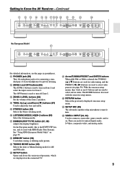
...multichannel DVD input. H POWER switch American and Australian models don't have this button again selects the previous listening mode. When set to OFF, the AV receiver is completely shutdown. When set to ON, it . C ZONE 2 indicator (83) Lights up when Zone 2 is the main power switch. F...North American and Australian models Front flap Push here to On or Standby. This is on. A STANDBY/ON button (39) Sets the AV receiver to open the flap The actual front panel has various logos printed on Standby and flashes while a signal is selected. E Display...
...multichannel DVD input. H POWER switch American and Australian models don't have this button again selects the previous listening mode. When set to OFF, the AV receiver is completely shutdown. When set to ON, it . C ZONE 2 indicator (83) Lights up when Zone 2 is the main power switch. F...North American and Australian models Front flap Push here to On or Standby. This is on. A STANDBY/ON button (39) Sets the AV receiver to open the flap The actual front panel has various logos printed on Standby and flashes while a signal is selected. E Display...
Instruction Manual
Page 9
... listening. U Arrow/TUNING/PRESET and ENTER buttons When AM, FM, or XM is for connecting a standard pair of the Zone 2 speakers. Getting to Know the AV Receiver-Continued K L M N O P QRS T U V W X PHONES ZONE 2 OFF TONE ZONE 2 LEVEL STEREO TUNING DIMMER MEMORY MODE SETUP RETURN ENTER SETUP MIC LISTENING MODE CLEAR PRESET PRESET TUNING DIGITAL...
... listening. U Arrow/TUNING/PRESET and ENTER buttons When AM, FM, or XM is for connecting a standard pair of the Zone 2 speakers. Getting to Know the AV Receiver-Continued K L M N O P QRS T U V W X PHONES ZONE 2 OFF TONE ZONE 2 LEVEL STEREO TUNING DIMMER MEMORY MODE SETUP RETURN ENTER SETUP MIC LISTENING MODE CLEAR PRESET PRESET TUNING DIGITAL...
Instruction Manual
Page 10
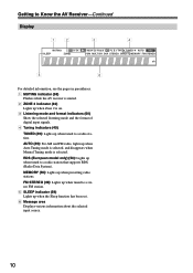
... (49): For AM and FM radio, lights up when tuned to a radio station. Getting to Know the AV Receiver-Continued Display 12 3 4 5 6 For detailed information, see the pages in parentheses. 1 MUTING indicator (58) Flashes while the AV receiver is muted. 2 ZONE 2 indicator (83) Lights up when Zone 2 is on. 3 Listening mode and format indicators...
... (49): For AM and FM radio, lights up when tuned to a radio station. Getting to Know the AV Receiver-Continued Display 12 3 4 5 6 For detailed information, see the pages in parentheses. 1 MUTING indicator (58) Flashes while the AV receiver is muted. 2 ZONE 2 indicator (83) Lights up when Zone 2 is on. 3 Listening mode and format indicators...
Instruction Manual
Page 11
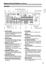
... M ZONE 2 LINE OUT This analog audio output can be connected to the IR IN jack, allowing you to the 12-volt trigger input on the AV receiver, a 12-volt trigger signal is turned on on a component in Zone 2. The HDMI inputs are for example, installed in Zone 2. 11 When Zone...for connecting components with component video outputs, such as CD players and DVD players. L IR IN/OUT A commercially available IR receiver can be connected to control the AV receiver while you're in Zone 2, or control it when it's out of sight, for connecting components with HDMI outputs, such as...
... M ZONE 2 LINE OUT This analog audio output can be connected to the IR IN jack, allowing you to the 12-volt trigger input on the AV receiver, a 12-volt trigger signal is turned on on a component in Zone 2. The HDMI inputs are for example, installed in Zone 2. 11 When Zone...for connecting components with component video outputs, such as CD players and DVD players. L IR IN/OUT A commercially available IR receiver can be connected to control the AV receiver while you're in Zone 2, or control it when it's out of sight, for connecting components with HDMI outputs, such as...
Instruction Manual
Page 12
...220-240 V." Y FRONT, CENTER, SURROUND, and SURROUND BACK SPEAKERS These terminal posts are connected digitally. O VOLTAGE SELECTOR (on another -capable Onkyo component, for remote and system control. There's S-Video and composite video input jacks for connecting the front L/R, center, surround L/R, and surround ...input and output jacks for connecting a DVD player. If it's between the AV receiver and the other AV components. Getting to Know the AV Receiver-Continued N RS232 This port is for connecting the AV receiver to select the correct setting. S CD IN This analog audio input is...
...220-240 V." Y FRONT, CENTER, SURROUND, and SURROUND BACK SPEAKERS These terminal posts are connected digitally. O VOLTAGE SELECTOR (on another -capable Onkyo component, for remote and system control. There's S-Video and composite video input jacks for connecting the front L/R, center, surround L/R, and surround ...input and output jacks for connecting a DVD player. If it's between the AV receiver and the other AV components. Getting to Know the AV Receiver-Continued N RS232 This port is for connecting the AV receiver to select the correct setting. S CD IN This analog audio input is...
Instruction Manual
Page 13
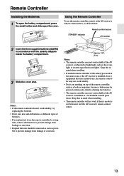
...corrosion. • Expired batteries should be pressed continuously, thereby draining the batteries. • The remote controller may not work reliably if the AV receiver is subjected to bright light, such as shown below. Keep this in mind when installing. • If another remote controller of batteries.... corrosion. 30˚ 30˚ Approx. 16 ft. (5 m) Notes: • The remote controller may not work reliably if the AV receiver is installed in accordance with the polarity diagram inside the battery compartment. 3 Slide the cover shut. Using the Remote Controller To use the ...
...corrosion. • Expired batteries should be pressed continuously, thereby draining the batteries. • The remote controller may not work reliably if the AV receiver is subjected to bright light, such as shown below. Keep this in mind when installing. • If another remote controller of batteries.... corrosion. 30˚ 30˚ Approx. 16 ft. (5 m) Notes: • The remote controller may not work reliably if the AV receiver is installed in accordance with the polarity diagram inside the battery compartment. 3 Slide the cover shut. Using the Remote Controller To use the ...
Instruction Manual
Page 14
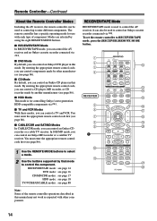
...a CD player, MD recorder, or CD recorder made by using the eight REMOTE MODE buttons. ■ RECEIVER/TAPE Mode In RECEIVER/TAPE mode, you can control the AV receiver and an Onkyo cassette recorder connected via . VCR CABLE CDR TOP MENU MENU ENTER SAT MD SLEEP VOL PREV CH DISPLAY...(see page 86). ■ HDD Mode This mode is used to control the AV receiver. Remote Controller-Continued About the Remote Controller Modes Including the AV receiver, the remote controller can be used to control an Onkyo cassette recorder connected via . ■ DVD Mode By default, you can control ...
...a CD player, MD recorder, or CD recorder made by using the eight REMOTE MODE buttons. ■ RECEIVER/TAPE Mode In RECEIVER/TAPE mode, you can control the AV receiver and an Onkyo cassette recorder connected via . VCR CABLE CDR TOP MENU MENU ENTER SAT MD SLEEP VOL PREV CH DISPLAY...(see page 86). ■ HDD Mode This mode is used to control the AV receiver. Remote Controller-Continued About the Remote Controller Modes Including the AV receiver, the remote controller can be used to control an Onkyo cassette recorder connected via . ■ DVD Mode By default, you can control ...
Instruction Manual
Page 15
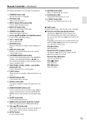
...buttons may not work properly with some cassette tapes. G CH +/- M MACRO buttons (90) Used with the Sleep function. Depending on the AV receiver. Stop [ ] button Stops playback. Remote Controller-Continued For detailed information, see the pages in parentheses. E DIMMER button (58) Adjusts the... display brightness. O REMOTE MODE buttons (14) Used to Standby. R VOL [ ]/[ ] button (48) Adjusts the volume of the AV receiver regardless of the current track. The Next [ ] button selects the next track. REC [ ] button Starts recording. 15 I DISPLAY button (59...
...buttons may not work properly with some cassette tapes. G CH +/- M MACRO buttons (90) Used with the Sleep function. Depending on the AV receiver. Stop [ ] button Stops playback. Remote Controller-Continued For detailed information, see the pages in parentheses. E DIMMER button (58) Adjusts the... display brightness. O REMOTE MODE buttons (14) Used to Standby. R VOL [ ]/[ ] button (48) Adjusts the volume of the AV receiver regardless of the current track. The Next [ ] button selects the next track. REC [ ] button Starts recording. 15 I DISPLAY button (59...
Instruction Manual
Page 18
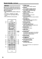
...; Connect the RI Dock to the TAPE IN or VIDEO 3 IN jacks. • Set the RI Dock's RI MODE switch to HDD. • Set the AV receiver's Input Display to HDD (see page 46). • Refer to select the previous song. B ON button* Turns on automatically. (With 3rd generation iPods, this button... works as a Play/Pause button.) H Rewind [ ] button Press and hold to select the previous or next playlist on the backlight for controlling Onkyo's next generation HDD-compatible components. Press it twice to the RI Dock's instruction manual. J REPEAT button* Used with the...
...; Connect the RI Dock to the TAPE IN or VIDEO 3 IN jacks. • Set the RI Dock's RI MODE switch to HDD. • Set the AV receiver's Input Display to HDD (see page 46). • Refer to select the previous song. B ON button* Turns on automatically. (With 3rd generation iPods, this button... works as a Play/Pause button.) H Rewind [ ] button Press and hold to select the previous or next playlist on the backlight for controlling Onkyo's next generation HDD-compatible components. Press it twice to the RI Dock's instruction manual. J REPEAT button* Used with the...
Instruction Manual
Page 19
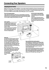
... 19 Position them behind the listener. Surround left and right speakers. Connecting Your Speakers Enjoying Home Theater Thanks to the AV receiver's superb capabilities, you can enjoy Dolby Pro Logic IIx and Onkyo's own DSP surround listening modes. They should be positioned facing the listener at the same height as shown. Their role...
... 19 Position them behind the listener. Surround left and right speakers. Connecting Your Speakers Enjoying Home Theater Thanks to the AV receiver's superb capabilities, you can enjoy Dolby Pro Logic IIx and Onkyo's own DSP surround listening modes. They should be positioned facing the listener at the same height as shown. Their role...

Instruction Manual
Page 20
... output the same sound in accordance with the above table. Powered subwoofer LINE INPUT LINE INPUT Attaching the Speaker Labels The AV receiver's positive (+) speaker terminals are color-coded for ease of identification. (The negative (-) speaker terminals are all ...8 1. Dipole speakers TV/screen 1 2 3 4 Normal speakers TV/screen 1 2 3 4 Connecting a Powered Subwoofer Using a suitable cable, connect the AV receiver's SUBWOOFER PRE OUT to indicate how they should be positioned so that their arrows point toward the TV/screen, while the surround back left * ✓...
... output the same sound in accordance with the above table. Powered subwoofer LINE INPUT LINE INPUT Attaching the Speaker Labels The AV receiver's positive (+) speaker terminals are color-coded for ease of identification. (The negative (-) speaker terminals are all ...8 1. Dipole speakers TV/screen 1 2 3 4 Normal speakers TV/screen 1 2 3 4 Connecting a Powered Subwoofer Using a suitable cable, connect the AV receiver's SUBWOOFER PRE OUT to indicate how they should be positioned so that their arrows point toward the TV/screen, while the surround back left * ✓...


