
Owner Manual
Page 5
... Terrestrial Set-top box, or Other Video Source 32 Connecting a Game Console 33 Connecting a Camcorder or Other Device 34 Connecting a Portable Audio player 34 Connecting a CD Player or Turntable 35 Connecting a Cassette, CDR, MiniDisc, or DAT Recorder 36 Connecting a Power Amplifier 37 Connecting...108 Preprogrammed Remote Control Codes 108 Looking up for Remote Control Code 108 Entering Remote Control Codes 110 Remote Control Codes for Onkyo Components Connected via V 111 Resetting REMOTE MODE Buttons 111 Resetting the Remote Controller 111 Controlling a TV 112 Controlling a DVD ...
... Terrestrial Set-top box, or Other Video Source 32 Connecting a Game Console 33 Connecting a Camcorder or Other Device 34 Connecting a Portable Audio player 34 Connecting a CD Player or Turntable 35 Connecting a Cassette, CDR, MiniDisc, or DAT Recorder 36 Connecting a Power Amplifier 37 Connecting...108 Preprogrammed Remote Control Codes 108 Looking up for Remote Control Code 108 Entering Remote Control Codes 110 Remote Control Codes for Onkyo Components Connected via V 111 Resetting REMOTE MODE Buttons 111 Resetting the Remote Controller 111 Controlling a TV 112 Controlling a DVD ...
Owner Manual
Page 6
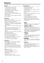
...is a registered trademark & the DTS logos, Symbol, DTS-HD Master Audio and DTS Surround Sensation are trademarks of DTS, Inc. ©1996-2008 DTS, Inc. To receive HD Radio broadcasts, you must install an Onkyo UP-HT1 HD Radio tuner module (sold separately). *7. Rock/Sports/Action.../RPG • Non-Scaling Configuration • Direct Mode and Pure Audio Mode • Music Optimizer*4 for Digital Music Files • A-Form Listening...
...is a registered trademark & the DTS logos, Symbol, DTS-HD Master Audio and DTS Surround Sensation are trademarks of DTS, Inc. ©1996-2008 DTS, Inc. To receive HD Radio broadcasts, you must install an Onkyo UP-HT1 HD Radio tuner module (sold separately). *7. Rock/Sports/Action.../RPG • Non-Scaling Configuration • Direct Mode and Pure Audio Mode • Music Optimizer*4 for Digital Music Files • A-Form Listening...
Owner Manual
Page 7
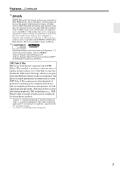
.... Taxes and a one-time activation fee may apply. U.S. THX Select2 Plus receivers also feature proprietary THX technologies (e.g., THX Mode) which is a registered trademark of Niles Audio Corporation. * Apple and iPod are trademarks of Xantech Corporation. * "Niles" is your guarantee that the Home Theater products you purchase will give you superb performance...
.... Taxes and a one-time activation fee may apply. U.S. THX Select2 Plus receivers also feature proprietary THX technologies (e.g., THX Mode) which is a registered trademark of Niles Audio Corporation. * Apple and iPod are trademarks of Xantech Corporation. * "Niles" is your guarantee that the Home Theater products you purchase will give you superb performance...

Owner Manual
Page 9
...item. When the onscreen setup menus are used to adjust the volume of stereo headphones for composite video, analog audio, and optical digital audio. V AUX INPUT HDMI (25) Used to connect a portable Audio Player. R Arrow, TUNING, PRESET and ENTER buttons When the AM or FM input source is selected, the...the AV receiver to connect a camcorder, game console, and so on page 93. PORTABLE (34): Used to connect a HD camcorder etc. W PURE AUDIO button and indicator (69) Selects the Pure Audio listening mode. There are used to -2 dB, -81.5 dB through +18.0 dB (relative display).
...item. When the onscreen setup menus are used to adjust the volume of stereo headphones for composite video, analog audio, and optical digital audio. V AUX INPUT HDMI (25) Used to connect a portable Audio Player. R Arrow, TUNING, PRESET and ENTER buttons When the AM or FM input source is selected, the...the AV receiver to connect a camcorder, game console, and so on page 93. PORTABLE (34): Used to connect a HD camcorder etc. W PURE AUDIO button and indicator (69) Selects the Pure Audio listening mode. There are used to -2 dB, -81.5 dB through +18.0 dB (relative display).
Owner Manual
Page 10
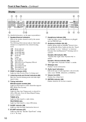
... current listening mode. D Listening mode and format indicators (69) Show the selected listening mode and audio input signal format. The following abbreviations indicate which audio channels are plugged into the PHONES jack. FM STEREO (61): Lights up when the Sleep function ... LM H Headphone indicator (58) Lights up when tuned to a stereo FM station. B Speaker/channel indicators Indicate the speaker channels used . K Audio input indicators Indicate the type of headphones are outputted for AM or FM radio. L Volume level (56) Displays the volume level. F SLEEP indicator...
... current listening mode. D Listening mode and format indicators (69) Show the selected listening mode and audio input signal format. The following abbreviations indicate which audio channels are plugged into the PHONES jack. FM STEREO (61): Lights up when the Sleep function ... LM H Headphone indicator (58) Lights up when tuned to a stereo FM station. B Speaker/channel indicators Indicate the speaker channels used . K Audio input indicators Indicate the type of headphones are outputted for AM or FM radio. L Volume level (56) Displays the volume level. F SLEEP indicator...
Owner Manual
Page 11
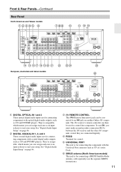
... SIRIUS antenna (North American models) This jack is for connecting components with coaxial digital audio outputs, such as CD and DVD/BD players. To use V, you can be used to an V jack on another Onkyo AV component. They're assignable, which means you can then be connected to control that... component. They're assignable, which means you must make an analog audio connection (RCA) between the AV receiver and the other AV component,...
... SIRIUS antenna (North American models) This jack is for connecting components with coaxial digital audio outputs, such as CD and DVD/BD players. To use V, you can be used to an V jack on another Onkyo AV component. They're assignable, which means you can then be connected to control that... component. They're assignable, which means you must make an analog audio connection (RCA) between the AV receiver and the other AV component,...
Owner Manual
Page 12
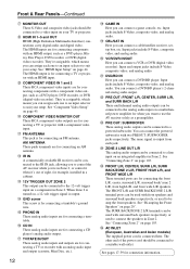
...you can assign each one to an input selector to a suitable wall outlet. Input jacks include S-Video, composite video, and analog audio. You can connect the powered subwoofer with surround back speakers respectively, or used with two PREOUT: SUBWOOFER jacks respectively. See "Bi-amping...-volt trigger input on an integrated amplifier in Zone 2. W PRE OUT: FRONT L/R, CENTER, SURR L/R, and SURR BACK L/R These multichannel analog audio outputs can connect a game console, etc. See pages 17-39 for connecting components with a component video output, such as a DVD player, ...
...you can assign each one to an input selector to a suitable wall outlet. Input jacks include S-Video, composite video, and analog audio. You can connect the powered subwoofer with surround back speakers respectively, or used with two PREOUT: SUBWOOFER jacks respectively. See "Bi-amping...-volt trigger input on an integrated amplifier in Zone 2. W PRE OUT: FRONT L/R, CENTER, SURR L/R, and SURR BACK L/R These multichannel analog audio outputs can connect a game console, etc. See pages 17-39 for connecting components with a component video output, such as a DVD player, ...
Owner Manual
Page 14
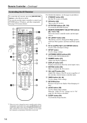
...to select and adjust settings. F SP LAYOUT button (58) This button is disabled. J DIMMER button (57) Adjusts the display brightness. P AUDIO button (99) Used to control your DVD/BD player, CD player, and other components. C ON button (40) Turns on the AV receiver...of the currently selected remote controller mode. B C K3 D E *1 L M 4 F N 1G H O P I LISTENING MODE buttons (69) Used to change audio settings. E REMOTE MODE/INPUT SELECTOR buttons (56, 112 to the previous display when changing settings. I 5 2J Q For detailed information, see the pages in parentheses....
...to select and adjust settings. F SP LAYOUT button (58) This button is disabled. J DIMMER button (57) Adjusts the display brightness. P AUDIO button (99) Used to control your DVD/BD player, CD player, and other components. C ON button (40) Turns on the AV receiver...of the currently selected remote controller mode. B C K3 D E *1 L M 4 F N 1G H O P I LISTENING MODE buttons (69) Used to change audio settings. E REMOTE MODE/INPUT SELECTOR buttons (56, 112 to the previous display when changing settings. I 5 2J Q For detailed information, see the pages in parentheses....
Owner Manual
Page 23
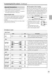
..., and yellow. Jack HDMI V OPTICAL L R Description HDMI connections can cause noise or malfunctions). • To prevent interference, keep audio and video cables away from power cords and speaker cables. Component video separates the luminance (Y) and color difference signals (PR, PB), ...connections (loose connections can carry uncompressed standard- It's the most common connection format for coaxial. This cable carries analog audio. 23 The audio quality is commonly used on virtually all the way. Connecting the AV receiver-Continued About AV Connections • Before...
..., and yellow. Jack HDMI V OPTICAL L R Description HDMI connections can cause noise or malfunctions). • To prevent interference, keep audio and video cables away from power cords and speaker cables. Component video separates the luminance (Y) and color difference signals (PR, PB), ...connections (loose connections can carry uncompressed standard- It's the most common connection format for coaxial. This cable carries analog audio. 23 The audio quality is commonly used on virtually all the way. Connecting the AV receiver-Continued About AV Connections • Before...
Owner Manual
Page 24
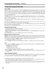
... a DVI input can display the picture. Notes: • Do not connect the -compatible component more than the above audio formats. ■ Onkyo for System Control , which allows system control over HDMI, is a new digital interface standard for digital video signals. Other... devices connected to eight channels of digital audio (2-channel PCM, multichannel digital audio, and multichannel PCM). c. The HDMI video stream (i.e., video...
... a DVI input can display the picture. Notes: • Do not connect the -compatible component more than the above audio formats. ■ Onkyo for System Control , which allows system control over HDMI, is a new digital interface standard for digital video signals. Other... devices connected to eight channels of digital audio (2-channel PCM, multichannel digital audio, and multichannel PCM). c. The HDMI video stream (i.e., video...
Owner Manual
Page 25
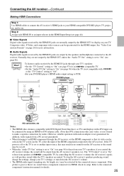
... To stop the AV receiver's speakers producing sound, change the settings, change your TV's settings, or turn down the AV receiver's volume. • The HDMI audio signal (sampling rate, bit length, etc.) may be cut off or the TV is set to another input source, this may result in the HDMI... Input Setup (see page 44). ■ Video Signals Digital video signals received by the HDMI IN jacks are output by the HDMI OUT for audio.) However, reliable operation with a DVI input can be output from your TV's speakers: • Set the "TV Control" setting to "On" (see page 96). ...
... To stop the AV receiver's speakers producing sound, change the settings, change your TV's settings, or turn down the AV receiver's volume. • The HDMI audio signal (sampling rate, bit length, etc.) may be cut off or the TV is set to another input source, this may result in the HDMI... Input Setup (see page 44). ■ Video Signals Digital video signals received by the HDMI IN jacks are output by the HDMI OUT for audio.) However, reliable operation with a DVI input can be output from your TV's speakers: • Set the "TV Control" setting to "On" (see page 96). ...
Owner Manual
Page 26
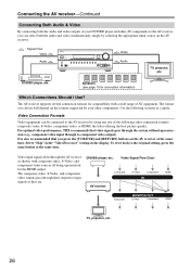
... depend on the formats supported by using any one of the following sections as a guide. Video Connection Formats Video equipment can select both the audio and video outputs of your other AV components to the AV receiver, you press the [VCR/DVR] and [RETURN] buttons on the display.... shown, with a wide range of AV equipment. Speakers (see page 19 for the HDMI output. Connecting the AV receiver-Continued Connecting Both Audio & Video By connecting both the audio and video simultaneously simply by selecting the appropriate input source on the AV receiver. : Signal Flow Video...
... depend on the formats supported by using any one of the following sections as a guide. Video Connection Formats Video equipment can select both the audio and video outputs of your other AV components to the AV receiver, you press the [VCR/DVR] and [RETURN] buttons on the display.... shown, with a wide range of AV equipment. Speakers (see page 19 for the HDMI output. Connecting the AV receiver-Continued Connecting Both Audio & Video By connecting both the audio and video simultaneously simply by selecting the appropriate input source on the AV receiver. : Signal Flow Video...
Owner Manual
Page 27
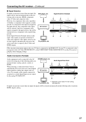
... AV receiver's display when changing settings. If your TV is connected to the input selector, this will be selected automatically in the following audio con- If signals are present at more than one input, the DVD player, etc. Composite MONITOR OUT S-Video Component HDMI In the Signal... Selection Example shown on the "Audio TV Out" setting TV, projector, etc. (see page 96). source and video is automatically selected as no component video input is connected to...
... AV receiver's display when changing settings. If your TV is connected to the input selector, this will be selected automatically in the following audio con- If signals are present at more than one input, the DVD player, etc. Composite MONITOR OUT S-Video Component HDMI In the Signal... Selection Example shown on the "Audio TV Out" setting TV, projector, etc. (see page 96). source and video is automatically selected as no component video input is connected to...
Owner Manual
Page 28
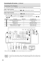
... c . (To record or listen in Zone 2 as well, use connection b or c , you need to TV programs through the AV receiver (see page 46). Step 2: Audio Connection Choose an audio connection that matches your TV ( A , B , or C ), and then make the connection. • With connection a , you use a and b , or a and c .) Connection A B C...DIGITAL COAXIAL IN 2 (VCR/DVR) DIGITAL OPTICAL IN 1 (GAME) Signal flow TV, projector, etc. When you can listen to and record audio from your VCR or cable or satellite receiver to the AV receiver and use its tuner to listen to assign the digital...
... c . (To record or listen in Zone 2 as well, use connection b or c , you need to TV programs through the AV receiver (see page 46). Step 2: Audio Connection Choose an audio connection that matches your TV ( A , B , or C ), and then make the connection. • With connection a , you use a and b , or a and c .) Connection A B C...DIGITAL COAXIAL IN 2 (VCR/DVR) DIGITAL OPTICAL IN 1 (GAME) Signal flow TV, projector, etc. When you can listen to and record audio from your VCR or cable or satellite receiver to the AV receiver and use its tuner to listen to assign the digital...
Owner Manual
Page 29
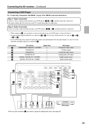
... C ), and then make the connection. Connecting the AV receiver-Continued Connecting a DVD Player See "Connecting Components with HDMI" on page 24 for connection a . Step 2: Audio Connection Choose an audio connection that matches your TV via the same type of connection. You must connect the AV receiver to assign the digital... VIDEO OUT DVD player When you use the main left and right outputs, be sure to use connection c , you can listen to and record audio from your DVD player or listen in Zone 2. • To enjoy Dolby Digital and DTS, use connection b or c . (To record or...
... C ), and then make the connection. Connecting the AV receiver-Continued Connecting a DVD Player See "Connecting Components with HDMI" on page 24 for connection a . Step 2: Audio Connection Choose an audio connection that matches your TV via the same type of connection. You must connect the AV receiver to assign the digital... VIDEO OUT DVD player When you use the main left and right outputs, be sure to use connection c , you can listen to and record audio from your DVD player or listen in Zone 2. • To enjoy Dolby Digital and DTS, use connection b or c . (To record or...
Owner Manual
Page 30
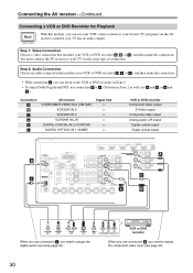
... to assign the component video input (see page 46). With this hookup, you need to assign the digital audio input (see page 45). 30 Step 2: Audio Connection Choose an audio connection that matches your TV via the AV receiver, useful if your VCR or DVD recorder ( a , ...GAME) Signal flow VCR or DVD recorder Component video output S-Video output Composite video output Analog audio L/R output Digital coaxial output Digital optical output A b C c a B COAXIAL OUT L R OPTICAL OUT AUDIO OUT S VIDEO OUT VIDEO Y PB PR OUT COMPONENT VIDEO OUT VCR or DVD recorder ...
... to assign the component video input (see page 46). With this hookup, you need to assign the digital audio input (see page 45). 30 Step 2: Audio Connection Choose an audio connection that matches your TV via the AV receiver, useful if your VCR or DVD recorder ( a , ...GAME) Signal flow VCR or DVD recorder Component video output S-Video output Composite video output Analog audio L/R output Digital coaxial output Digital optical output A b C c a B COAXIAL OUT L R OPTICAL OUT AUDIO OUT S VIDEO OUT VIDEO Y PB PR OUT COMPONENT VIDEO OUT VCR or DVD recorder ...
Owner Manual
Page 31
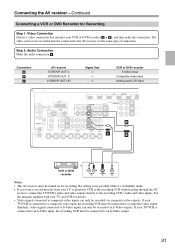
...OUT V VCR/DVR OUT L/R Signal flow ⇒ ⇒ ⇒ VCR or DVD recorder S-Video input Composite video input Analog audio L/R input B a A VCR or DVD recorder L R AUDIO IN S VIDEO IN VIDEO IN Notes: • The AV receiver must be connected to the AV receiver via the same type ... video outputs directly to a composite video input, the recording VCR must be recorded via S-Video outputs. Step 2: Audio Connection Make the audio connection a . Similarly, video signals connected to S-Video inputs can only be turned on for Recording Step 1: Video Connection Choose a ...
...OUT V VCR/DVR OUT L/R Signal flow ⇒ ⇒ ⇒ VCR or DVD recorder S-Video input Composite video input Analog audio L/R input B a A VCR or DVD recorder L R AUDIO IN S VIDEO IN VIDEO IN Notes: • The AV receiver must be connected to the AV receiver via the same type ... video outputs directly to a composite video input, the recording VCR must be recorded via S-Video outputs. Step 2: Audio Connection Make the audio connection a . Similarly, video signals connected to S-Video inputs can only be turned on for Recording Step 1: Video Connection Choose a ...
Owner Manual
Page 32
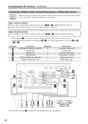
... the AV receiver-Continued Connecting a Satellite, Cable, Terrestrial Set-top box, or Other Video Source Hint! When you use connection c , you need to and record audio from the video source or listen in Zone 2. • To enjoy Dolby Digital and DTS, use connection b or c . (To record or listen in Zone 2 as... well, use your satellite or cable receiver to listen to your TV has no audio outputs. You must connect the AV receiver to your favorite TV programs via the AV receiver, useful if your TV via the same type of...
... the AV receiver-Continued Connecting a Satellite, Cable, Terrestrial Set-top box, or Other Video Source Hint! When you use connection c , you need to and record audio from the video source or listen in Zone 2. • To enjoy Dolby Digital and DTS, use connection b or c . (To record or listen in Zone 2 as... well, use your satellite or cable receiver to listen to your TV has no audio outputs. You must connect the AV receiver to your favorite TV programs via the AV receiver, useful if your TV via the same type of...
Owner Manual
Page 33
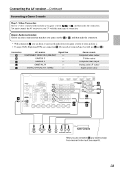
... game console ( A , B , or C ), and then make the connection. • With connection a , you can listen to and record audio from your game console or listen in Zone 2. • To enjoy Dolby Digital and DTS, use connection b . (To record or listen in Zone...V GAME IN L/R DIGITAL OPTICAL IN 1 (GAME) Signal flow Game console Component video output S-Video output Composite video output Analog audio L/R output Digital optical output A C b a B L R OPTICAL OUT AUDIO OUT S VIDEO OUT VIDEO Y PB PR OUT COMPONENT VIDEO OUT Game Console When you use connection A , you need to your...
... game console ( A , B , or C ), and then make the connection. • With connection a , you can listen to and record audio from your game console or listen in Zone 2. • To enjoy Dolby Digital and DTS, use connection b . (To record or listen in Zone...V GAME IN L/R DIGITAL OPTICAL IN 1 (GAME) Signal flow Game console Component video output S-Video output Composite video output Analog audio L/R output Digital optical output A C b a B L R OPTICAL OUT AUDIO OUT S VIDEO OUT VIDEO Y PB PR OUT COMPONENT VIDEO OUT Game Console When you use connection A , you need to your...
Owner Manual
Page 34
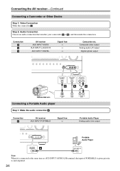
... L AUDIO R b A a Camcorder etc. OPTICAL OUT Connecting a Portable Audio player Step 1: Make the audio connection a . VIDEO OUT L AUDIO R OUT Connection a AV receiver AUX INPUT PORTABLE Signal flow ⇐ Portable Audio Player Analog audio Line output Portable Audio Player AUX INPUT PORTABLE a AUDIO LINE OUT...receiver-Continued Connecting a Camcorder or Other Device Step 1: Video Connection Make the connection A . Step 2: Audio Connection Choose an audio connection that matches your camcorder ( a or b ), and then make the connection. Connection A a b AV receiver AUX ...
... L AUDIO R b A a Camcorder etc. OPTICAL OUT Connecting a Portable Audio player Step 1: Make the audio connection a . VIDEO OUT L AUDIO R OUT Connection a AV receiver AUX INPUT PORTABLE Signal flow ⇐ Portable Audio Player Analog audio Line output Portable Audio Player AUX INPUT PORTABLE a AUDIO LINE OUT...receiver-Continued Connecting a Camcorder or Other Device Step 1: Video Connection Make the connection A . Step 2: Audio Connection Choose an audio connection that matches your camcorder ( a or b ), and then make the connection. Connection A a b AV receiver AUX ...


