Owner Manual
Page 1
Please read this manual thoroughly before making connections and plugging in this manual for purchasing the Onkyo AV Receiver. Contents Introduction Important Safeguards 2 Precautions 3 Supplied Accessories 4 Features 4 Before Using the TX-SR501/TX-SR501E 5 Controls & Connectors 6 Connections Connecting Your AV Components 10 Connecting -compatible AV Components ........19 Installing Your Speakers 20 Connecting Antenna 22 Setup Powering Up & Setting Up the...
Please read this manual thoroughly before making connections and plugging in this manual for purchasing the Onkyo AV Receiver. Contents Introduction Important Safeguards 2 Precautions 3 Supplied Accessories 4 Features 4 Before Using the TX-SR501/TX-SR501E 5 Controls & Connectors 6 Connections Connecting Your AV Components 10 Connecting -compatible AV Components ........19 Installing Your Speakers 20 Connecting Antenna 22 Setup Powering Up & Setting Up the...
Owner Manual
Page 2
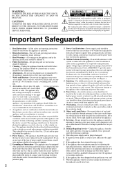
... should be read before cleaning. Damage Requiring Service-Unplug the appliance form the wall outlet and refer servicing to dangerous voltage or other controls may be free space of electric shock to your home, consult your appliance dealer or local power company. 12. The appliance may..., unplug it is damaged, B. If the appliance has been exposed to replace your electrician to rain or water, D. Adjust only those controls that they exit from the wall outlet before the appliance is intended to alert the user to grounding electrodes, and requirements for service. PORTABLE...
... should be read before cleaning. Damage Requiring Service-Unplug the appliance form the wall outlet and refer servicing to dangerous voltage or other controls may be free space of electric shock to your home, consult your appliance dealer or local power company. 12. The appliance may..., unplug it is damaged, B. If the appliance has been exposed to replace your electrician to rain or water, D. Adjust only those controls that they exit from the wall outlet before the appliance is intended to alert the user to grounding electrodes, and requirements for service. PORTABLE...
Owner Manual
Page 4
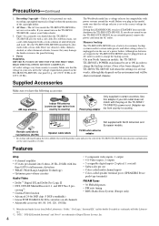
...optical, 1 coaxial) • Subwoofer pre out • Color-coded multi-channel inputs • Color-coded speaker terminal posts (SPEAKERS B use the TX-SR501/TX-SR501E for your AC outlet does not match with power systems around the ...name indicates the color of the TX-SR501/TX-SR501E. Memory backup The TX-SR501/TX-SR501E uses a battery-less memory backup system in order to country. Remote controller & two batteries (AA/R6)...shutdown the TX-SR501/TX-SR501E. "DTS," "DTS-ES Extended Surround," and "Neo:6" are required, the TX-SR501/TX-SR501E must be shorter in your Onkyo dealer. 3.
...optical, 1 coaxial) • Subwoofer pre out • Color-coded multi-channel inputs • Color-coded speaker terminal posts (SPEAKERS B use the TX-SR501/TX-SR501E for your AC outlet does not match with power systems around the ...name indicates the color of the TX-SR501/TX-SR501E. Memory backup The TX-SR501/TX-SR501E uses a battery-less memory backup system in order to country. Remote controller & two batteries (AA/R6)...shutdown the TX-SR501/TX-SR501E. "DTS," "DTS-ES Extended Surround," and "Neo:6" are required, the TX-SR501/TX-SR501E must be shorter in your Onkyo dealer. 3.
Owner Manual
Page 5
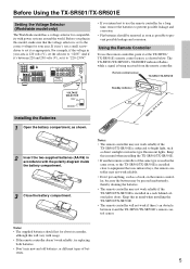
... controller, point it as direct sunlight or inverter-type fluorescent lights. For example, if the voltage in a rack behind colored glass doors. And if it's between it to set the selector to bright light, such as appropriate. The TX-SR501/TX-SR501E's STANDBY indicator flashes while a signal is being received from the remote controller...
... controller, point it as direct sunlight or inverter-type fluorescent lights. For example, if the voltage in a rack behind colored glass doors. And if it's between it to set the selector to bright light, such as appropriate. The TX-SR501/TX-SR501E's STANDBY indicator flashes while a signal is being received from the remote controller...
Owner Manual
Page 6
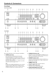
... to OFF, the TX-SR501/TX-SR501E is a problem, plug the TX-SR501/TX-SR501E into a different branch circuit. Note: Turning on the power until you've completed, and double checked all connections (pages 10-23). R ST U B STANDBY/ON button (24) This button is used to assign the digital inputs. Controls & Connectors Front Panel North American Model... L AUDIO R NO PQ For detailed information, refer to ON. A POWER switch (24) The North American model doesn't have this is completely shutdown. This is being received from the remote controller.
... to OFF, the TX-SR501/TX-SR501E is a problem, plug the TX-SR501/TX-SR501E into a different branch circuit. Note: Turning on the power until you've completed, and double checked all connections (pages 10-23). R ST U B STANDBY/ON button (24) This button is used to assign the digital inputs. Controls & Connectors Front Panel North American Model... L AUDIO R NO PQ For detailed information, refer to ON. A POWER switch (24) The North American model doesn't have this is completely shutdown. This is being received from the remote controller.
Owner Manual
Page 7
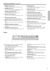
...33) This indicator lights up when speaker set B is on. 2 MUTING indicator (33) This indicator flashes when the TX-SR501/TX-SR501E is muted. 3 Source/listening mode indicators (28, 36) These indicators display information about the currently selected source. N SPEAKER ...the Sleep function has been set the volume of the TX-SR501/ TX-SR501E. Display 12 3 4 5 6 For detailed information, refer to turn speaker sets A and B on . J Remote control sensor (5) This sensor receives control signals from the remote controller. AUTO (30): This indicator lights up when programming ...
...33) This indicator lights up when speaker set B is on. 2 MUTING indicator (33) This indicator flashes when the TX-SR501/TX-SR501E is muted. 3 Source/listening mode indicators (28, 36) These indicators display information about the currently selected source. N SPEAKER ...the Sleep function has been set the volume of the TX-SR501/ TX-SR501E. Display 12 3 4 5 6 For detailed information, refer to turn speaker sets A and B on . J Remote control sensor (5) This sensor receives control signals from the remote controller. AUTO (30): This indicator lights up when programming ...
Owner Manual
Page 8
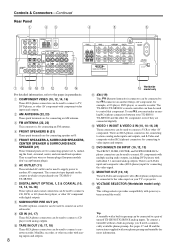
...The FRONT, SURR, CENTER, and SUBWOOFER RCA/ phono connectors can be used to another Onkyo AV component, for connecting to connect a cassette recorder, MiniDisc recorder, or other AV component. See pages 17 and 18 and the instructions supplied with digital outputs. The .... 8 O Worldwide model only K (19) This (Remote Interactive) connector can be used to the video input on your TX-SR501/ TX-SR501E and the other AV component with your TX-SR501/ TX-SR501E. Controls & Connectors-Continued Rear Panel 1 23 4 5 6 COMPONENT VIDEO ANTENNA VIDEO 1 / 2 / 3 DVD IN IN OUT...
...The FRONT, SURR, CENTER, and SUBWOOFER RCA/ phono connectors can be used to another Onkyo AV component, for connecting to connect a cassette recorder, MiniDisc recorder, or other AV component. See pages 17 and 18 and the instructions supplied with digital outputs. The .... 8 O Worldwide model only K (19) This (Remote Interactive) connector can be used to the video input on your TX-SR501/ TX-SR501E and the other AV component with your TX-SR501/ TX-SR501E. Controls & Connectors-Continued Rear Panel 1 23 4 5 6 COMPONENT VIDEO ANTENNA VIDEO 1 / 2 / 3 DVD IN IN OUT...
Owner Manual
Page 9
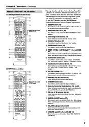
... with the remote controller. L Remote Controller Mode buttons (28, 40, 42) These buttons are used to set the TX-SR501/TX-SR501E to On or Standby. M SP A & SP B buttons (28, 32) These buttons are used to select the listening modes. For detailed information, refer to the pages in RCVR mode (Receiver mode). H Input... O ADJUST [ ] [ ] buttons (37) These buttons are used to select radio presets. J PRESET [ ] [ ] buttons (31) These buttons are explained on using the remote controller to control your other AV components, are used to adjust the functions selected with the remote...
... with the remote controller. L Remote Controller Mode buttons (28, 40, 42) These buttons are used to set the TX-SR501/TX-SR501E to On or Standby. M SP A & SP B buttons (28, 32) These buttons are used to select the listening modes. For detailed information, refer to the pages in RCVR mode (Receiver mode). H Input... O ADJUST [ ] [ ] buttons (37) These buttons are used to select radio presets. J PRESET [ ] [ ] buttons (31) These buttons are explained on using the remote controller to control your other AV components, are used to adjust the functions selected with the remote...
Owner Manual
Page 11
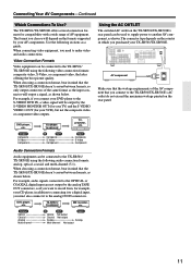
..., you connect to another AV component, as a guide. TX-SR501/ TX-SR501E MD recorder, etc. COMPONENT VIDEO ANTENNA VIDEO 1 / 2 / 3 DVD IN IN OUT AM FM 75 Y PB PR DIGITAL INPUT OPTICAL COAXIAL 2 1 REMOTE CONTROL VIDEO 2 IN VIDEO 1...AV equipment. L R R R SURROUND BACK SPEAKER AV component Make sure that the wattage requirements of the AV component that the TX-SR501/TX-SR501E doesn't convert between formats, as shown below . The format you want to the TX-SR501/ TX-SR501E using the following sections as shown. Output Optical Coaxial Analog Multi-channel...
..., you connect to another AV component, as a guide. TX-SR501/ TX-SR501E MD recorder, etc. COMPONENT VIDEO ANTENNA VIDEO 1 / 2 / 3 DVD IN IN OUT AM FM 75 Y PB PR DIGITAL INPUT OPTICAL COAXIAL 2 1 REMOTE CONTROL VIDEO 2 IN VIDEO 1...AV equipment. L R R R SURROUND BACK SPEAKER AV component Make sure that the wattage requirements of the AV component that the TX-SR501/TX-SR501E doesn't convert between formats, as shown below . The format you want to the TX-SR501/ TX-SR501E using the following sections as shown. Output Optical Coaxial Analog Multi-channel...
Owner Manual
Page 12
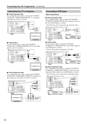
...Use an S-Video cable to connect the TX-SR501/ TX-SR501E's S VIDEO MONITOR OUT to an S-Video input on your TV, as shown. COMPONENT VIDEO ANTENNA VIDEO 1 / 2 / 3 DVD IN IN OUT AM FM 75 Y PB PR DIGITAL INPUT OPTICAL COAXIAL 2 1 REMOTE CONTROL VIDEO 2 IN VIDEO 1 OUT IN... 2 VIDEO 1 R DVD SUB WOOFER OUT Y PB PR TV, projector, etc. Connecting Your AV Components-Continued Connecting Your TV or Projector ■ Using Composite Video Use a composite video cable to connect the TX-SR501/ TX-SR501E's VIDEO MONITOR OUT to a composite video input on your TV, as shown.
...Use an S-Video cable to connect the TX-SR501/ TX-SR501E's S VIDEO MONITOR OUT to an S-Video input on your TV, as shown. COMPONENT VIDEO ANTENNA VIDEO 1 / 2 / 3 DVD IN IN OUT AM FM 75 Y PB PR DIGITAL INPUT OPTICAL COAXIAL 2 1 REMOTE CONTROL VIDEO 2 IN VIDEO 1 OUT IN... 2 VIDEO 1 R DVD SUB WOOFER OUT Y PB PR TV, projector, etc. Connecting Your AV Components-Continued Connecting Your TV or Projector ■ Using Composite Video Use a composite video cable to connect the TX-SR501/ TX-SR501E's VIDEO MONITOR OUT to a composite video input on your TV, as shown.
Owner Manual
Page 13
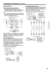
... ANTENNA VIDEO 1 / 2 / 3 DVD IN IN OUT AM FM 75 Y PB PR DIGITAL INPUT OPTICAL COAXIAL 2 1 REMOTE CONTROL VIDEO 2 IN VIDEO 1 OUT IN DVD MONITOR IN OUT VIDEO S VIDEO IN OUT IN L SUBWOOFER PRE OUT R CD TAPE ...channel RCA/phono audio cable to connect the TX-SR501/TX-SR501E's L/R FRONT, L/R SURR, CENTER, and SUB WOOFER DVD IN connectors to the 5.1 analog outputs on your DVD player, as shown. Connecting Your AV Components-Continued Audio Connections ■ Using Optical or Coaxial Connections • Use an optical digital audio cable to connect the TX-SR501/TX...
... ANTENNA VIDEO 1 / 2 / 3 DVD IN IN OUT AM FM 75 Y PB PR DIGITAL INPUT OPTICAL COAXIAL 2 1 REMOTE CONTROL VIDEO 2 IN VIDEO 1 OUT IN DVD MONITOR IN OUT VIDEO S VIDEO IN OUT IN L SUBWOOFER PRE OUT R CD TAPE ...channel RCA/phono audio cable to connect the TX-SR501/TX-SR501E's L/R FRONT, L/R SURR, CENTER, and SUB WOOFER DVD IN connectors to the 5.1 analog outputs on your DVD player, as shown. Connecting Your AV Components-Continued Audio Connections ■ Using Optical or Coaxial Connections • Use an optical digital audio cable to connect the TX-SR501/TX...

Owner Manual
Page 14
...be connected via S-Video. COMPONENT VIDEO ANTENNA VIDEO 1 / 2 / 3 IN OUT AM FM 75 Y PB PR DIGITAL INPUT OPTICAL COAXIAL 2 1 REMOTE CONTROL VIDEO 2 IN VIDEO 1 OUT IN DVD MONITOR IN OUT VIDEO S VIDEO IN OUT IN L SUBWOOFER PRE OUT R CD TAPE IN OUT IN FRONT SURR ...VHS recorder, as shown. OR • Use an optical digital audio cable to connect the TX-SR501/TX-SR501E's OPTICAL 2 DIGITAL INPUT to the optical output on your VCR, as shown. Connecting Your AV Components-Continued Connecting a VCR for Playback Video Connections • Use an S-Video cable to ...
...be connected via S-Video. COMPONENT VIDEO ANTENNA VIDEO 1 / 2 / 3 IN OUT AM FM 75 Y PB PR DIGITAL INPUT OPTICAL COAXIAL 2 1 REMOTE CONTROL VIDEO 2 IN VIDEO 1 OUT IN DVD MONITOR IN OUT VIDEO S VIDEO IN OUT IN L SUBWOOFER PRE OUT R CD TAPE IN OUT IN FRONT SURR ...VHS recorder, as shown. OR • Use an optical digital audio cable to connect the TX-SR501/TX-SR501E's OPTICAL 2 DIGITAL INPUT to the optical output on your VCR, as shown. Connecting Your AV Components-Continued Connecting a VCR for Playback Video Connections • Use an S-Video cable to ...
Owner Manual
Page 15
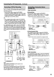
... RCA/phono audio cable to connect the TX-SR501/TX-SR501E's L/R VIDEO 1 OUT connectors to your VCR's AV inputs. STANDBY/ON POWER ON OFF A SPEAKERS B PHONES STANDBY DISPLAY SUBWOOFER DIMMER DIGITAL INPUT MODE CH SEL LEVEL CONTROL SUBWOOFER LEVEL DIRECT STEREO SURROUND DSP ADJUST ...Using S-Video Use an S-Video cable to connect the TX-SR501/ TX-SR501E's S VIDEO VIDEO 3 INPUT to record. STANDBY/ON POWER ON OFF A SPEAKERS B PHONES STANDBY DISPLAY SUBWOOFER DIMMER DIGITAL INPUT MODE CH SEL LEVEL CONTROL SUBWOOFER LEVEL DIRECT STEREO SURROUND DSP ADJUST SPEAKER ADJUST ...
... RCA/phono audio cable to connect the TX-SR501/TX-SR501E's L/R VIDEO 1 OUT connectors to your VCR's AV inputs. STANDBY/ON POWER ON OFF A SPEAKERS B PHONES STANDBY DISPLAY SUBWOOFER DIMMER DIGITAL INPUT MODE CH SEL LEVEL CONTROL SUBWOOFER LEVEL DIRECT STEREO SURROUND DSP ADJUST ...Using S-Video Use an S-Video cable to connect the TX-SR501/ TX-SR501E's S VIDEO VIDEO 3 INPUT to record. STANDBY/ON POWER ON OFF A SPEAKERS B PHONES STANDBY DISPLAY SUBWOOFER DIMMER DIGITAL INPUT MODE CH SEL LEVEL CONTROL SUBWOOFER LEVEL DIRECT STEREO SURROUND DSP ADJUST SPEAKER ADJUST ...
Owner Manual
Page 16
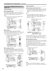
...doesn't have digital audio outputs, or you want to the S-Video output on your satellite/cable tuner, LD player, etc., as shown. Connecting Your AV Components-Continued Connecting a Satellite/Cable Tuner, LD player, etc. COMPONENT VIDEO ANTENNA VIDEO 1 / 2 / 3 DVD IN IN OUT AM FM ... Using Composite Video Use a composite video cable to connect the TX-SR501/ TX-SR501E's VIDEO VIDEO 2 IN to OPTICAL 2. COMPONENT VIDEO ANTENNA VIDEO 1 / 2 / 3 DVD IN IN OUT AM FM 75 Y PB PR DIGITAL INPUT OPTICAL COAXIAL 2 1 REMOTE CONTROL VIDEO 2 IN VIDEO 1 OUT IN DVD MONITOR IN OUT ...
...doesn't have digital audio outputs, or you want to the S-Video output on your satellite/cable tuner, LD player, etc., as shown. Connecting Your AV Components-Continued Connecting a Satellite/Cable Tuner, LD player, etc. COMPONENT VIDEO ANTENNA VIDEO 1 / 2 / 3 DVD IN IN OUT AM FM ... Using Composite Video Use a composite video cable to connect the TX-SR501/ TX-SR501E's VIDEO VIDEO 2 IN to OPTICAL 2. COMPONENT VIDEO ANTENNA VIDEO 1 / 2 / 3 DVD IN IN OUT AM FM 75 Y PB PR DIGITAL INPUT OPTICAL COAXIAL 2 1 REMOTE CONTROL VIDEO 2 IN VIDEO 1 OUT IN DVD MONITOR IN OUT ...
Owner Manual
Page 17
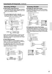
...R AUDIO INPUT L R CD player AUDIO OUTPUT L R 17 Connecting Your AV Components-Continued Connecting a CD Player ■ Using Coaxial or Optical Connections • Use a coaxial digital audio cable to connect the TX-SR501/ TX-SR501E's COAXIAL DIGITAL INPUT to the analog audio outputs on your CD player,... audio cable to connect the TX-SR501/TX-SR501E's OPTICAL 2 DIGITAL INPUT to the audio outputs on your turntable, as shown. COMPONENT VIDEO ANTENNA VIDEO 1 / 2 / 3 DVD IN IN OUT AM FM 75 Y PB PR DIGITAL INPUT OPTICAL COAXIAL 2 1 REMOTE CONTROL VIDEO 2 IN VIDEO 1 ...
...R AUDIO INPUT L R CD player AUDIO OUTPUT L R 17 Connecting Your AV Components-Continued Connecting a CD Player ■ Using Coaxial or Optical Connections • Use a coaxial digital audio cable to connect the TX-SR501/ TX-SR501E's COAXIAL DIGITAL INPUT to the analog audio outputs on your CD player,... audio cable to connect the TX-SR501/TX-SR501E's OPTICAL 2 DIGITAL INPUT to the audio outputs on your turntable, as shown. COMPONENT VIDEO ANTENNA VIDEO 1 / 2 / 3 DVD IN IN OUT AM FM 75 Y PB PR DIGITAL INPUT OPTICAL COAXIAL 2 1 REMOTE CONTROL VIDEO 2 IN VIDEO 1 ...

Owner Manual
Page 18
...use another RCA/phono audio cable to connect the TX-SR501/TX-SR501E's L/R TAPE OUT connectors to the cassette recorders inputs, as shown. COMPONENT VIDEO ANTENNA VIDEO 1 / 2 / 3 DVD IN IN OUT AM FM 75 Y PB PR DIGITAL INPUT OPTICAL COAXIAL 2 1 REMOTE CONTROL VIDEO 2 IN VIDEO 1 OUT IN DVD MONITOR...to your turntable, as shown. Use another RCA/phono audio cable to connect the TX-SR501/TX-SR501E's L/R TAPE OUT connectors to the DAT or CD/MD recorder inputs, as shown. Connecting Your AV Components-Continued ■ Turntable with an MC-type (Moving Coil) Cartridge Use an ...
...use another RCA/phono audio cable to connect the TX-SR501/TX-SR501E's L/R TAPE OUT connectors to the cassette recorders inputs, as shown. COMPONENT VIDEO ANTENNA VIDEO 1 / 2 / 3 DVD IN IN OUT AM FM 75 Y PB PR DIGITAL INPUT OPTICAL COAXIAL 2 1 REMOTE CONTROL VIDEO 2 IN VIDEO 1 OUT IN DVD MONITOR...to your turntable, as shown. Use another RCA/phono audio cable to connect the TX-SR501/TX-SR501E's L/R TAPE OUT connectors to the DAT or CD/MD recorder inputs, as shown. Connecting Your AV Components-Continued ■ Turntable with an MC-type (Moving Coil) Cartridge Use an ...
Owner Manual
Page 19
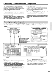
... CD player, DVD player, and cassette recorder. making any connections! Example: Onkyo DVD player Connecting several -compatible Onkyo AV components DIGITAL OUT OPTICAL REMOTE CONTROL L R ANALOG OUTPUT TX-SR501/TX-SR501E REMOTE CONTROL connector Onkyo CD player cable You must make an analog RCA/phono connection between your TX-SR501/TX-SR501E and the other connector is already on. ■ Auto Source...
... CD player, DVD player, and cassette recorder. making any connections! Example: Onkyo DVD player Connecting several -compatible Onkyo AV components DIGITAL OUT OPTICAL REMOTE CONTROL L R ANALOG OUTPUT TX-SR501/TX-SR501E REMOTE CONTROL connector Onkyo CD player cable You must make an analog RCA/phono connection between your TX-SR501/TX-SR501E and the other connector is already on. ■ Auto Source...
Owner Manual
Page 21
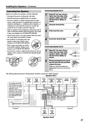
... the manual suppliedPRwith VIDEO 2 IN your subwoofer for more than 6 ohms may damage your TX-SR501/TX-SR501E. • Unnecessarily long, or very thin speaker cables may damage your TX-SR501/TX-SR501E. • If you want to which speakers should be avoided. • Be careful... the terminal. 3 Fully insert the wire. 5/8" (15 mm) 4 Screw the terminal tight. Doing so may damage your TX-SR501/TX-SR501E. • Don't connect more DIGITAL INPUT REMOTE CONTROL OPTICAL COAXIAL information. 2 1 VIDEO 1 OUT IN DVD MONITOR IN OUT VIDEO S VIDEO IN OUT IN L SUBWOOFER PRE ...
... the manual suppliedPRwith VIDEO 2 IN your subwoofer for more than 6 ohms may damage your TX-SR501/TX-SR501E. • Unnecessarily long, or very thin speaker cables may damage your TX-SR501/TX-SR501E. • If you want to which speakers should be avoided. • Be careful... the terminal. 3 Fully insert the wire. 5/8" (15 mm) 4 Screw the terminal tight. Doing so may damage your TX-SR501/TX-SR501E. • Don't connect more DIGITAL INPUT REMOTE CONTROL OPTICAL COAXIAL information. 2 1 VIDEO 1 OUT IN DVD MONITOR IN OUT VIDEO S VIDEO IN OUT IN L SUBWOOFER PRE ...
Owner Manual
Page 22
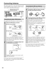
... terminals FM antenna connector COMPONENT VIDEO ANTENNA VIDEO 1 / 2 / 3 DVD IN IN OUT AM FM 75 Y PB PR DIGITAL INPUT OPTICAL COAXIAL 2 1 REMOTE CONTROL VIDEO 2 IN VIDEO 1 OUT IN DVD MONITOR IN OUT VIDEO S VIDEO IN OUT IN L SUBWOOFER PRE OUT R CD TAPE IN OUT IN FRONT SURR CENTER... Model FM 75 Insert the plug fully into the socket. ■ Other Models FM 75 Insert the plug fully into the socket. Once your TX-SR501/TX-SR501E, TV, speaker cables, and power cords. Make sure that the wires are attached securely and that you cannot achieve good reception with a...
... terminals FM antenna connector COMPONENT VIDEO ANTENNA VIDEO 1 / 2 / 3 DVD IN IN OUT AM FM 75 Y PB PR DIGITAL INPUT OPTICAL COAXIAL 2 1 REMOTE CONTROL VIDEO 2 IN VIDEO 1 OUT IN DVD MONITOR IN OUT VIDEO S VIDEO IN OUT IN L SUBWOOFER PRE OUT R CD TAPE IN OUT IN FRONT SURR CENTER... Model FM 75 Insert the plug fully into the socket. ■ Other Models FM 75 Insert the plug fully into the socket. Once your TX-SR501/TX-SR501E, TV, speaker cables, and power cords. Make sure that the wires are attached securely and that you cannot achieve good reception with a...
Owner Manual
Page 24
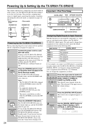
... from OPTICAL 1 to COAXIAL. Notes: • The TX-SR501/TX-SR501E is shipped with the [POWER] switch in the ON position. • To completely shutdown the TX-SR501/TX-SR501E, press the [POWER] switch. • The remote controller has no assignment). To turn on the same circuit. ...the display lights up, and the STANDBY indicator goes off the TX-SR501/TX-SR501E, press the [STANDBY/ON] button. The TX-SR501/TX-SR501E comes on the TX-SR501/TX-SR501E may cause a momentary power surge that you connect your speakers and AV components (see page 10 to page 21). 1 Connect the...
... from OPTICAL 1 to COAXIAL. Notes: • The TX-SR501/TX-SR501E is shipped with the [POWER] switch in the ON position. • To completely shutdown the TX-SR501/TX-SR501E, press the [POWER] switch. • The remote controller has no assignment). To turn on the same circuit. ...the display lights up, and the STANDBY indicator goes off the TX-SR501/TX-SR501E, press the [STANDBY/ON] button. The TX-SR501/TX-SR501E comes on the TX-SR501/TX-SR501E may cause a momentary power surge that you connect your speakers and AV components (see page 10 to page 21). 1 Connect the...


