Owner Manual
Page 1
... 40 Using the Remote Controller RC-518M with Your Other AV Components 41 Appendix Troubleshooting 45 Specifications 48 En Please read this manual will enable you for future reference. Please retain this manual for purchasing the Onkyo AV Receiver. AV Receiver TX-SR501 TX-SR501E Instruction Manual Thank you to obtain optimum performance and listening enjoyment from your new...
... 40 Using the Remote Controller RC-518M with Your Other AV Components 41 Appendix Troubleshooting 45 Specifications 48 En Please read this manual will enable you for future reference. Please retain this manual for purchasing the Onkyo AV Receiver. AV Receiver TX-SR501 TX-SR501E Instruction Manual Thank you to obtain optimum performance and listening enjoyment from your new...
Owner Manual
Page 2
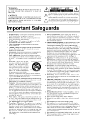
WARNING AVIS RISK OF ELECTRIC SHOCK RISQUE DE CHOC ELECTRIQUE DO NOT OPEN NE PAS OUVRIR The lightning flash with arrowhead symbol, within an equilateral triangle, is intended to alert the user to the presence of important operating and maintenance (servicing) instructions in the literature accompanying the appliance. The exclamation point within the product's enclosure that could result in a risk of time, unplug it can result in a fire or electric shock. Important Safeguards 1. or near water -for service. The openings should be equipped with a cart, stand...
WARNING AVIS RISK OF ELECTRIC SHOCK RISQUE DE CHOC ELECTRIQUE DO NOT OPEN NE PAS OUVRIR The lightning flash with arrowhead symbol, within an equilateral triangle, is intended to alert the user to the presence of important operating and maintenance (servicing) instructions in the literature accompanying the appliance. The exclamation point within the product's enclosure that could result in a risk of time, unplug it can result in a fire or electric shock. Important Safeguards 1. or near water -for service. The openings should be equipped with a cart, stand...
Owner Manual
Page 3
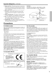
...Live As the colours of the wires in particular, specifies that it is encouraged to try to the terminal which the receiver is in compliance with the letter N or coloured black. Replacement Parts-When replacement parts are required, be performed only by ASTA ... that interference will not occur in a particular installation. For European Models Declaration of any doubt, consult a qualified electrician. MORI ONKYO EUROPE ELECTRONICS GmbH FIGURE 1: EXAMPLE OF ANTENNA GROUNDING AS PER NATIONAL ELECTRICAL CODE, ANSI/NFPA 70 GROUND CLAMP ELECTRIC SERVICE EQUIPMENT NEC - Mod...
...Live As the colours of the wires in particular, specifies that it is encouraged to try to the terminal which the receiver is in compliance with the letter N or coloured black. Replacement Parts-When replacement parts are required, be performed only by ASTA ... that interference will not occur in a particular installation. For European Models Declaration of any doubt, consult a qualified electrician. MORI ONKYO EUROPE ELECTRONICS GmbH FIGURE 1: EXAMPLE OF ANTENNA GROUNDING AS PER NATIONAL ELECTRICAL CODE, ANSI/NFPA 70 GROUND CLAMP ELECTRIC SERVICE EQUIPMENT NEC - Mod...
Owner Manual
Page 4
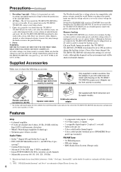
..., alcohol, or other settings when it has been charged, the TX-SR501/TX-SR501E will be shorter in your Onkyo dealer. 3. AC outlet voltages vary from country to STANDBY does not fully shutdown the TX-SR501/TX-SR501E. Use this adapter if your area. Specifications and... FM/AM Tuner • 30 FM/AM presets • FM auto tuning • RDS (Radio Data System) (Europe only) *1. If you should dust the TX-SR501/ TX-SR501E all channels • Adjustable crossover (60, 80, 100, 120, 150 Hz) • 2 component video inputs, 1 output • 4 S-Video inputs, 2 outputs •...
..., alcohol, or other settings when it has been charged, the TX-SR501/TX-SR501E will be shorter in your Onkyo dealer. 3. AC outlet voltages vary from country to STANDBY does not fully shutdown the TX-SR501/TX-SR501E. Use this adapter if your area. Specifications and... FM/AM Tuner • 30 FM/AM presets • FM auto tuning • RDS (Radio Data System) (Europe only) *1. If you should dust the TX-SR501/ TX-SR501E all channels • Adjustable crossover (60, 80, 100, 120, 150 Hz) • 2 component video inputs, 1 output • 4 S-Video inputs, 2 outputs •...
Owner Manual
Page 5
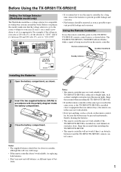
...AC OUTLET SWITCHED 100W MAX. Keep this will not work reliably. • Don't put anything, such as shown below. Before Using the TX-SR501/TX-SR501E Setting the Voltage Selector (Worldwide model only) The Worldwide model has a voltage selector for compatibility with the polarity diagram inside the battery ...reliably, try replacing both batteries. • Don't mix new and old batteries, or different types of the same type is being received from the remote controller. Before you intend not to use the remote controller, point it to prevent possible leakage and corrosion. •...
...AC OUTLET SWITCHED 100W MAX. Keep this will not work reliably. • Don't put anything, such as shown below. Before Using the TX-SR501/TX-SR501E Setting the Voltage Selector (Worldwide model only) The Worldwide model has a voltage selector for compatibility with the polarity diagram inside the battery ...reliably, try replacing both batteries. • Don't mix new and old batteries, or different types of the same type is being received from the remote controller. Before you intend not to use the remote controller, point it to prevent possible leakage and corrosion. •...
Owner Manual
Page 6
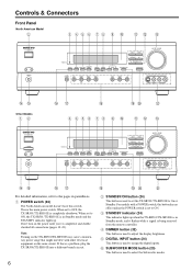
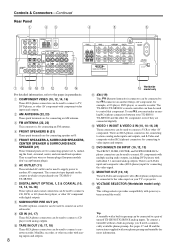
...C STANDBY indicator (24) This indicator lights up . E DIGITAL INPUT button (24) This button is the main power switch. When set the TX-SR501/TX-SR501E to On or Standby. R ST U B STANDBY/ON button (24) This button is completely shutdown. When set to adjust the display ...TX-SR501/TX-SR501E is used to ON, the TX-SR501/TX-SR501E is in Standby mode and the STANDBY indicator lights up when the TX-SR501/TX-SR501E is in parenthesis. F SUBWOOFER MODE button (25) This button is used to the pages in Standby mode, and it flashes while a signal is being received...
...C STANDBY indicator (24) This indicator lights up . E DIGITAL INPUT button (24) This button is the main power switch. When set the TX-SR501/TX-SR501E to On or Standby. R ST U B STANDBY/ON button (24) This button is completely shutdown. When set to adjust the display ...TX-SR501/TX-SR501E is used to ON, the TX-SR501/TX-SR501E is in Standby mode and the STANDBY indicator lights up when the TX-SR501/TX-SR501E is in parenthesis. F SUBWOOFER MODE button (25) This button is used to the pages in Standby mode, and it flashes while a signal is being received...
Owner Manual
Page 7
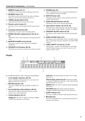
...(5) This sensor receives control signals from the remote controller. P DISPLAY button (32) This button is used to display various information about the currently selected source and listening mode. 4 Tuning indicators (30, 31) TUNED (30): This indicator lights up when the TX-SR501E is on...the pages in parenthesis. 1 A & B speaker indicators (28, 32) Indicator A lights up when the Sleep function has been set the volume of the TX-SR501/ TX-SR501E. L PRESET/ADJUST [ ] [ ] buttons (25, 26, 31, 37) This button is used to adjust various speaker-related parameters. S SPEAKER ...
...(5) This sensor receives control signals from the remote controller. P DISPLAY button (32) This button is used to display various information about the currently selected source and listening mode. 4 Tuning indicators (30, 31) TUNED (30): This indicator lights up when the TX-SR501E is on...the pages in parenthesis. 1 A & B speaker indicators (28, 32) Indicator A lights up when the Sleep function has been set the volume of the TX-SR501/ TX-SR501E. L PRESET/ADJUST [ ] [ ] buttons (25, 26, 31, 37) This button is used to adjust various speaker-related parameters. S SPEAKER ...
Owner Manual
Page 8
... connectors can be used to connect a TV, DVD player, or other AV component with your TX-SR501/ TX-SR501E. To use , you must make an analog RCA/phono connection between your TX-SR501/ TX-SR501E and the other recorder with a built-in which you 'll need...Onkyo AV component, for connecting the video signal. C FM ANTENNA (22, 23) This connector is for connecting speaker set B. F AC OUTLET (11) This switched AC outlet can be used to connect an active subwoofer. I CD IN (10, 17) These RCA/phono connectors can be connected to the connector on another AV component. The TX-SR501/TX...
... connectors can be used to connect a TV, DVD player, or other AV component with your TX-SR501/ TX-SR501E. To use , you must make an analog RCA/phono connection between your TX-SR501/ TX-SR501E and the other recorder with a built-in which you 'll need...Onkyo AV component, for connecting the video signal. C FM ANTENNA (22, 23) This connector is for connecting speaker set B. F AC OUTLET (11) This switched AC outlet can be used to connect an active subwoofer. I CD IN (10, 17) These RCA/phono connectors can be connected to the connector on another AV component. The TX-SR501/TX...
Owner Manual
Page 9
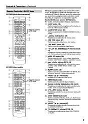
... mode 5 M N O 6 7 8 9 P RC-479S (other AV components, are used to select the remote controller modes. J PRESET [ ] [ ] buttons (31) These buttons are used to the pages in RCVR mode (Receiver mode). For detailed information, refer to set only with the remote controller. This... function can be set only with the remote controller. This function can be set the volume of each speaker individually. G AUDIO SEL button (29) This button is used to mute the TX-SR501/TX...
... mode 5 M N O 6 7 8 9 P RC-479S (other AV components, are used to select the remote controller modes. J PRESET [ ] [ ] buttons (31) These buttons are used to the pages in RCVR mode (Receiver mode). For detailed information, refer to set only with the remote controller. This... function can be set only with the remote controller. This function can be set the volume of each speaker individually. G AUDIO SEL button (29) This button is used to mute the TX-SR501/TX...
Owner Manual
Page 10
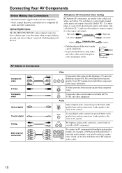
...DVD player with individual 5.1 surround analog outputs, you 've completed all the way. AV Cables & Connectors Component video S-Video Composite video PR / CR PB /CB Y Optical digital Coaxial digital Analog Multi-channel connection PR / CR PB / CB Y Video Component video separates the luminance (Y) ...manuals supplied with your AV components. • Don't connect the power cord until you need to make a good connection. • To prevent interference, keep audio and video cables away from power cords and speaker cables. Optical Digital Inputs The TX-SR501/TX-SR501E's optical digital...
...DVD player with individual 5.1 surround analog outputs, you 've completed all the way. AV Cables & Connectors Component video S-Video Composite video PR / CR PB /CB Y Optical digital Coaxial digital Analog Multi-channel connection PR / CR PB / CB Y Video Component video separates the luminance (Y) ...manuals supplied with your AV components. • Don't connect the power cord until you need to make a good connection. • To prevent interference, keep audio and video cables away from power cords and speaker cables. Optical Digital Inputs The TX-SR501/TX-SR501E's optical digital...
Owner Manual
Page 11
... Formats Audio equipment can be connected to another AV component, as shown below . For example, audio signals connected to the TX-SR501/ TX-SR501E using the following audio connection formats: analog, optical, coaxial, and multi-channel (5.1). L R R R SURROUND BACK SPEAKER AV component Make sure that the wattage requirements of AV equipment. COMPONENT VIDEO ANTENNA VIDEO 1 / 2 / 3 DVD IN IN...
... Formats Audio equipment can be connected to another AV component, as shown below . For example, audio signals connected to the TX-SR501/ TX-SR501E using the following audio connection formats: analog, optical, coaxial, and multi-channel (5.1). L R R R SURROUND BACK SPEAKER AV component Make sure that the wattage requirements of AV equipment. COMPONENT VIDEO ANTENNA VIDEO 1 / 2 / 3 DVD IN IN...
Owner Manual
Page 12
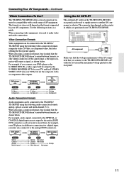
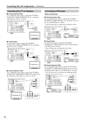
... WOOFER MONITOR OUT S VIDEO S VIDEO IN TV, projector, etc. ■ Using Component Video Use a component video cable to connect the TX-SR501/ TX-SR501E's COMPONENT VIDEO OUT connectors to the component video inputs on your DVD player, as shown. • Your TV must also be connected ... 1 R DVD SUB WOOFER OUT Y PB PR TV, projector, etc. Connecting Your AV Components-Continued Connecting Your TV or Projector ■ Using Composite Video Use a composite video cable to connect the TX-SR501/ TX-SR501E's VIDEO MONITOR OUT to a composite video input on your DVD player, as shown...
... WOOFER MONITOR OUT S VIDEO S VIDEO IN TV, projector, etc. ■ Using Component Video Use a component video cable to connect the TX-SR501/ TX-SR501E's COMPONENT VIDEO OUT connectors to the component video inputs on your DVD player, as shown. • Your TV must also be connected ... 1 R DVD SUB WOOFER OUT Y PB PR TV, projector, etc. Connecting Your AV Components-Continued Connecting Your TV or Projector ■ Using Composite Video Use a composite video cable to connect the TX-SR501/ TX-SR501E's VIDEO MONITOR OUT to a composite video input on your DVD player, as shown...
Owner Manual
Page 13
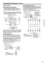
...OUT OPTICAL DIGITAL OUT COAXIAL COAXIAL FRONT L FRONT R SURR L SURR R CENTER SUBWOOFER ■ Using Multi-channel Connections Use a multi-channel RCA/phono audio cable to connect the TX-SR501/TX-SR501E's L/R FRONT, L/R SURR, CENTER, and SUB WOOFER DVD IN connectors to the 5.1 analog outputs on ...player CENTER L L R R FRONT SURR SUB WOOFER 13 Connecting Your AV Components-Continued Audio Connections ■ Using Optical or Coaxial Connections • Use an optical digital audio cable to connect the TX-SR501/TX-SR501E's OPTICAL 1 DIGITAL INPUT to the optical output on your DVD ...
...OUT OPTICAL DIGITAL OUT COAXIAL COAXIAL FRONT L FRONT R SURR L SURR R CENTER SUBWOOFER ■ Using Multi-channel Connections Use a multi-channel RCA/phono audio cable to connect the TX-SR501/TX-SR501E's L/R FRONT, L/R SURR, CENTER, and SUB WOOFER DVD IN connectors to the 5.1 analog outputs on ...player CENTER L L R R FRONT SURR SUB WOOFER 13 Connecting Your AV Components-Continued Audio Connections ■ Using Optical or Coaxial Connections • Use an optical digital audio cable to connect the TX-SR501/TX-SR501E's OPTICAL 1 DIGITAL INPUT to the optical output on your DVD ...

Owner Manual
Page 14
...8226; Use an optical digital audio cable to connect the TX-SR501/TX-SR501E's OPTICAL 2 DIGITAL INPUT to the optical output on your VCR, as shown. Your TV must also be connected via composite video. Connecting Your AV Components-Continued Connecting a VCR for Playback Video Connections •...; Use an S-Video cable to connect the TX-SR501/ TX-SR501E's S VIDEO VIDEO 2 IN to the S-Video output on your D-VHS ...
...8226; Use an optical digital audio cable to connect the TX-SR501/TX-SR501E's OPTICAL 2 DIGITAL INPUT to the optical output on your VCR, as shown. Your TV must also be connected via composite video. Connecting Your AV Components-Continued Connecting a VCR for Playback Video Connections •...; Use an S-Video cable to connect the TX-SR501/ TX-SR501E's S VIDEO VIDEO 2 IN to the S-Video output on your D-VHS ...
Owner Manual
Page 15
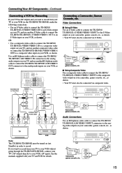
... 3 INPUT S VIDEO VIDEO L AUDIO R S VIDEO OUT Camcorder, games console, etc. VIDEO Audio Connections Use an RCA/phono audio cable to connect the TX-SR501/ TX-SR501E's L/R VIDEO 3 INPUT connectors to a composite video input on your camcorder, games console, etc., as shown. Video Connections ■ Using S-Video Use... the manuals supplied with your TV and VCR for Recording If your TV has AV outputs and you want to record from your TV to your VCR without going through the TX-SR501/TX-SR501E, connect your TV's AV outputs directly to an S-Video input on your VCR...
... 3 INPUT S VIDEO VIDEO L AUDIO R S VIDEO OUT Camcorder, games console, etc. VIDEO Audio Connections Use an RCA/phono audio cable to connect the TX-SR501/ TX-SR501E's L/R VIDEO 3 INPUT connectors to a composite video input on your camcorder, games console, etc., as shown. Video Connections ■ Using S-Video Use... the manuals supplied with your TV and VCR for Recording If your TV has AV outputs and you want to record from your TV to your VCR without going through the TX-SR501/TX-SR501E, connect your TV's AV outputs directly to an S-Video input on your VCR...
Owner Manual
Page 16
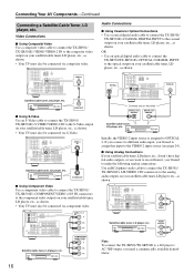
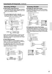
..., the VIDEO 2 input source is assigned to a LD player's AC-3RF output, you 'll need a commercially available demodulator. 16 Connecting Your AV Components-Continued Connecting a Satellite/Cable Tuner, LD player, etc. COMPONENT VIDEO ANTENNA VIDEO 1 / 2 / 3 DVD IN IN OUT AM FM 75... your satellite/cable tuner, LD player, etc., as shown. S VIDEO OUT ■ Using Component Video Use a component video cable to connect the TX-SR501/ TX-SR501E's COMPONENT VIDEO 1/2/3 IN connectors to the S-Video output on your satellite/cable tuner, LD player, etc., as shown. VIDEO 1 / 2...
..., the VIDEO 2 input source is assigned to a LD player's AC-3RF output, you 'll need a commercially available demodulator. 16 Connecting Your AV Components-Continued Connecting a Satellite/Cable Tuner, LD player, etc. COMPONENT VIDEO ANTENNA VIDEO 1 / 2 / 3 DVD IN IN OUT AM FM 75... your satellite/cable tuner, LD player, etc., as shown. S VIDEO OUT ■ Using Component Video Use a component video cable to connect the TX-SR501/ TX-SR501E's COMPONENT VIDEO 1/2/3 IN connectors to the S-Video output on your satellite/cable tuner, LD player, etc., as shown. VIDEO 1 / 2...
Owner Manual
Page 17
...Turntable without a Built-in Phono Preamp Use an RCA/phono audio cable to connect the TX-SR501/ TX-SR501E's L/R TAPE IN connectors to the audio outputs on your turntable, as shown. Connecting Your AV Components-Continued Connecting a CD Player ■ Using Coaxial or Optical Connections • Use... a coaxial digital audio cable to connect the TX-SR501/ TX-SR501E's COAXIAL DIGITAL INPUT to the coaxial output on your CD...
...Turntable without a Built-in Phono Preamp Use an RCA/phono audio cable to connect the TX-SR501/ TX-SR501E's L/R TAPE IN connectors to the audio outputs on your turntable, as shown. Connecting Your AV Components-Continued Connecting a CD Player ■ Using Coaxial or Optical Connections • Use... a coaxial digital audio cable to connect the TX-SR501/ TX-SR501E's COAXIAL DIGITAL INPUT to the coaxial output on your CD...

Owner Manual
Page 18
.../phono audio cable to connect the phono preamp's inputs to the cassette recorders inputs, as shown. Use another RCA/phono audio cable to connect the TX-SR501/TX-SR501E's L/R TAPE OUT connectors to your DAT or CD/MD recorder, as shown. COMPONENT VIDEO ANTENNA VIDEO 1 / 2 / 3 DVD IN IN ...to the cassette recorders outputs, and use another RCA/phono audio cable to connect the TX-SR501/TX-SR501E's L/R TAPE OUT connectors to the audio outputs on your MC head amp's outputs. Connecting Your AV Components-Continued ■ Turntable with an MC-type (Moving Coil) Cartridge Use an RCA...
.../phono audio cable to connect the phono preamp's inputs to the cassette recorders inputs, as shown. Use another RCA/phono audio cable to connect the TX-SR501/TX-SR501E's L/R TAPE OUT connectors to your DAT or CD/MD recorder, as shown. COMPONENT VIDEO ANTENNA VIDEO 1 / 2 / 3 DVD IN IN ...to the cassette recorders outputs, and use another RCA/phono audio cable to connect the TX-SR501/TX-SR501E's L/R TAPE OUT connectors to the audio outputs on your MC head amp's outputs. Connecting Your AV Components-Continued ■ Turntable with an MC-type (Moving Coil) Cartridge Use an RCA...
Owner Manual
Page 19
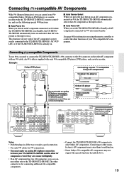
.... • Use only cables for connecting additional -compatible components. • Connect the TX-SR501/TX-SR501E's connector to the TX-SR501/TX-SR501E. making any connections! Example: Onkyo DVD player Connecting several -compatible Onkyo AV components DIGITAL OUT OPTICAL REMOTE CONTROL L R ANALOG OUTPUT TX-SR501/TX-SR501E REMOTE CONTROL connector Onkyo CD player cable You must make an analog RCA/phono connection between...
.... • Use only cables for connecting additional -compatible components. • Connect the TX-SR501/TX-SR501E's connector to the TX-SR501/TX-SR501E. making any connections! Example: Onkyo DVD player Connecting several -compatible Onkyo AV components DIGITAL OUT OPTICAL REMOTE CONTROL L R ANALOG OUTPUT TX-SR501/TX-SR501E REMOTE CONTROL connector Onkyo CD player cable You must make an analog RCA/phono connection between...
Owner Manual
Page 20
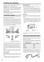
...by the other speakers. Installing Your Speakers You can still enjoy surround sound material by specifying the number of speakers connected, and the TX-SR501/TX-SR501E will produce the best surround sound possible with the available speakers. See page 34. Similarly, if you don't have a ...try to the positive (+) terminal, and one -third the width of speakers with Dolby Digital or DTS surround material, you like. The TX-SR501/TX-SR501E's positive (+) speaker terminals are color-coded for stereo speakers or where you can connect a pair of identification. (The ...
...by the other speakers. Installing Your Speakers You can still enjoy surround sound material by specifying the number of speakers connected, and the TX-SR501/TX-SR501E will produce the best surround sound possible with the available speakers. See page 34. Similarly, if you don't have a ...try to the positive (+) terminal, and one -third the width of speakers with Dolby Digital or DTS surround material, you like. The TX-SR501/TX-SR501E's positive (+) speaker terminals are color-coded for stereo speakers or where you can connect a pair of identification. (The ...