
Owner Manual
Page 1
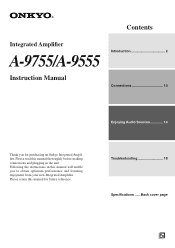
Please read this manual thoroughly before making connections and plugging in this manual for purchasing an Onkyo Integrated Amplifier. Back cover page En Please retain this manual will enable you for future reference. Following the instructions in the unit. Troubleshooting 18 Specifications ...... Contents Integrated Amplifier A-9755/A-9555 Introduction 2 Instruction Manual Connections 10 Enjoying Audio Sources 14 Thank you to obtain optimum performance and listening enjoyment from your new Integrated Amplifier.
Please read this manual thoroughly before making connections and plugging in this manual for purchasing an Onkyo Integrated Amplifier. Back cover page En Please retain this manual will enable you for future reference. Following the instructions in the unit. Troubleshooting 18 Specifications ...... Contents Integrated Amplifier A-9755/A-9555 Introduction 2 Instruction Manual Connections 10 Enjoying Audio Sources 14 Thank you to obtain optimum performance and listening enjoyment from your new Integrated Amplifier.
Owner Manual
Page 2
...prong are covered by the operating instructions as radiators, heat registers, stoves, or other controls may touch dangerous voltage points or short-out parts that are provided for your outlet, consult an electrician for service. 16. When the power-supply cord or plug is adequate ventilation. If ... use this indicates a need for replacement of the polarized or grounding-type plug. When a cart is intended to alert the user to qualified service personnel under the following the operating instructions. Leave 20 cm (8") of the shelf or board above the apparatus shall be set 10...
...prong are covered by the operating instructions as radiators, heat registers, stoves, or other controls may touch dangerous voltage points or short-out parts that are provided for your outlet, consult an electrician for service. 16. When the power-supply cord or plug is adequate ventilation. If ... use this indicates a need for replacement of the polarized or grounding-type plug. When a cart is intended to alert the user to qualified service personnel under the following the operating instructions. Leave 20 cm (8") of the shelf or board above the apparatus shall be set 10...
Owner Manual
Page 3
... leave marks on the power supply cord of this unit, have a voltage selector switch for a long time, because they may not work properly the next time you should be connected to the terminal which is marked with an appropriate fuse. For British models Replacement and mounting of an AC plug on the case. • This unit's top and rear panels may not correspond...
... leave marks on the power supply cord of this unit, have a voltage selector switch for a long time, because they may not work properly the next time you should be connected to the terminal which is marked with an appropriate fuse. For British models Replacement and mounting of an AC plug on the case. • This unit's top and rear panels may not correspond...
Owner Manual
Page 4
... 12 Connecting a TV or Other Component with an Audio Output 12 Connecting a Preamp (A-9755 only) ..... 13 Connecting Components 13 Enjoying Audio Sources Turning On the A-9755/A-9555 14 Selecting Speaker 14 Listening to Components 15 Muting the A-9755/A-9555 (remote controller only 15 Using Headphones 15 Using the Tone Controls 16 Setting the PURE DIRECT Function....16 Adjusting the Bass 16 Adjusting the Treble 16 Loudness Control 16 Using the MAIN IN Function (A-9755 only 17 Recording 17 Others Troubleshooting 18 Specifications 20...
... 12 Connecting a TV or Other Component with an Audio Output 12 Connecting a Preamp (A-9755 only) ..... 13 Connecting Components 13 Enjoying Audio Sources Turning On the A-9755/A-9555 14 Selecting Speaker 14 Listening to Components 15 Muting the A-9755/A-9555 (remote controller only 15 Using Headphones 15 Using the Tone Controls 16 Setting the PURE DIRECT Function....16 Adjusting the Bass 16 Adjusting the Treble 16 Loudness Control 16 Using the MAIN IN Function (A-9755 only 17 Recording 17 Others Troubleshooting 18 Specifications 20...
Owner Manual
Page 5
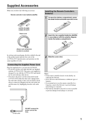
... name indicates the color of the A-9755/A-9555. Connecting the Supplied Power Cord Plug the supplied power cord into the wall outlet. Doing so may cause an electric shock. To wall outlet DO NOT connect the power cord at this AC INLET. • Do not use a power cord other end is designed for use the remote controller for a long time, remove the batteries to prevent damage from...
... name indicates the color of the A-9755/A-9555. Connecting the Supplied Power Cord Plug the supplied power cord into the wall outlet. Doing so may cause an electric shock. To wall outlet DO NOT connect the power cord at this AC INLET. • Do not use a power cord other end is designed for use the remote controller for a long time, remove the batteries to prevent damage from...

Owner Manual
Page 6
... selected input source. You can be used to Standby). H Volume control and indicator (15) This control is left unconnected. 6 I PURE DIRECT button and indicator (16) This button turns the PURE DIRECT function on and off . A POWER switch (14) This is turned down low. E BASS control (16) This control is for private listening. The indicator lights up while the MAIN IN function is in parentheses. M Remote control sensor (9) This sensor receives control signals from the following input sources: LINE, HDD, PHONO, CD, TUNER, TAPE...
... selected input source. You can be used to Standby). H Volume control and indicator (15) This control is left unconnected. 6 I PURE DIRECT button and indicator (16) This button turns the PURE DIRECT function on and off . A POWER switch (14) This is turned down low. E BASS control (16) This control is for private listening. The indicator lights up while the MAIN IN function is in parentheses. M Remote control sensor (9) This sensor receives control signals from the following input sources: LINE, HDD, PHONO, CD, TUNER, TAPE...
Owner Manual
Page 7
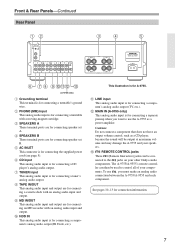
... connecting a turntable's ground wire. M REMOTE CONTROL jacks These (Remote Interactive) jacks can then be used to the jacks on your other Onkyo audio components. See pages 10-13 for connecting the supplied power cord (see page 5). D SPEAKERS B These terminal posts are for connecting a separate preamp when you must make an analog audio connection between the A-9755/A-9555 and each component. E AC INLET This connector is for connecting a tuner's analog audio output. H TAPE IN/OUT This analog audio input and output are for connecting speaker set...
... connecting a turntable's ground wire. M REMOTE CONTROL jacks These (Remote Interactive) jacks can then be used to the jacks on your other Onkyo audio components. See pages 10-13 for connecting the supplied power cord (see page 5). D SPEAKERS B These terminal posts are for connecting a separate preamp when you must make an analog audio connection between the A-9755/A-9555 and each component. E AC INLET This connector is for connecting a tuner's analog audio output. H TAPE IN/OUT This analog audio input and output are for connecting speaker set...
Owner Manual
Page 8
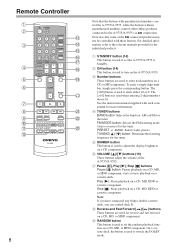
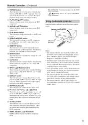
...) for more information. E DIMMER button The button is used to turn on the A-9755/A-9555. B ON button (14) This button is used to Standby. C Number buttons These buttons are used for the tuner. D TUNER buttons BAND button: Selects the band (ex. PRESET +/- button: Selects radio presets. Stop [ ]: Stops playback on a cassette deck. On a cassette deck, the button is used to set the random playback function on a CD component. A STANDBY button (14) This button is used to set the A-9755/A-9555 to adjust the display brightness on a CD, MD...
...) for more information. E DIMMER button The button is used to turn on the A-9755/A-9555. B ON button (14) This button is used to Standby. C Number buttons These buttons are used for the tuner. D TUNER buttons BAND button: Selects the band (ex. PRESET +/- button: Selects radio presets. Stop [ ]: Stops playback on a cassette deck. On a cassette deck, the button is used to set the random playback function on a CD component. A STANDBY button (14) This button is used to set the A-9755/A-9555 to adjust the display brightness on a CD, MD...
Owner Manual
Page 9
... HDD component. P ENTER button This button is used to select from the memory function program, etc., on a CD or MD component. R INPUT [ ]/[ ] buttons (15) These buttons are used to remove the last track from the following input sources: LINE, HDD, PHONO, CD, TUNER, TAPE or MD. Using the Remote Controller Point the remote controller toward the remote control sensor. N GROUP/SEARCH button This button selects groups on an HDD component. With memory playback, you can make a custom program. M PLAY MODE button This button sets...
... HDD component. P ENTER button This button is used to select from the memory function program, etc., on a CD or MD component. R INPUT [ ]/[ ] buttons (15) These buttons are used to remove the last track from the following input sources: LINE, HDD, PHONO, CD, TUNER, TAPE or MD. Using the Remote Controller Point the remote controller toward the remote control sensor. N GROUP/SEARCH button This button selects groups on an HDD component. With memory playback, you can make a custom program. M PLAY MODE button This button sets...
Owner Manual
Page 10
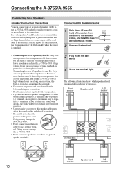
... speaker terminal. If you use speakers with an impedance of 8 ohms or more but less than one pair of speaker terminals. 3 Fully insert the bare wires. 4 Screw the terminal tight. Right speaker Speaker set A Left speaker -+ -+ A-9755/A-9555 -+ -+ Right speaker Speaker set outputs sound, or use the A-9755/A-9555 at the same time. Connecting the A-9755/A-9555 Connecting Your Speakers Speaker Connection Precautions You can connect one or two sets of speakers (A/B) to the A-9755/A-9555, and select which speaker should be connected...
... speaker terminal. If you use speakers with an impedance of 8 ohms or more but less than one pair of speaker terminals. 3 Fully insert the bare wires. 4 Screw the terminal tight. Right speaker Speaker set A Left speaker -+ -+ A-9755/A-9555 -+ -+ Right speaker Speaker set outputs sound, or use the A-9755/A-9555 at the same time. Connecting the A-9755/A-9555 Connecting Your Speakers Speaker Connection Precautions You can connect one or two sets of speakers (A/B) to the A-9755/A-9555, and select which speaker should be connected...
Owner Manual
Page 11
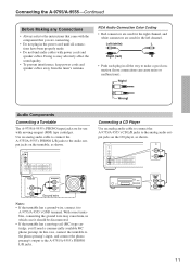
... phono preamp's output to make a good connection (loose connections can cause noise or malfunctions). Audio Components Connecting a Turntable The A-9755/A-9555's PHONO input jacks are for use with power cords and speaker cables. Doing so may cause hum, in the power cord until all the way to the A-9755/A-9555's PHONO L/R jacks. With some turntables, connecting the ground wire may adversely affect the sound quality. • To prevent interference, keep power cords and speaker cables away from the tuner's antenna...
... phono preamp's output to make a good connection (loose connections can cause noise or malfunctions). Audio Components Connecting a Turntable The A-9755/A-9555's PHONO input jacks are for use with power cords and speaker cables. Doing so may cause hum, in the power cord until all the way to the A-9755/A-9555's PHONO L/R jacks. With some turntables, connecting the ground wire may adversely affect the sound quality. • To prevent interference, keep power cords and speaker cables away from the tuner's antenna...
Owner Manual
Page 12
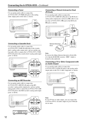
... RI MODE switch to "HDD" which is located on the underside. L AUDIO OUT Note: If you can connect the A-9755/A-9555 to an audio output on your TV has no audio output, you use its tuner. 12 REC (IN) PLAY (OUT) OUT Connecting a Cassette Deck Use an analog audio cable to connect the A-9755/A-9555's TAPE IN L/R jacks to the cassette deck's analog audio output jacks, and use another analog audio cable to connect the A-9755/A-9555's TAPE OUT L/R jacks to the cassette deck's analog audio input jacks, as shown. Connecting...
... RI MODE switch to "HDD" which is located on the underside. L AUDIO OUT Note: If you can connect the A-9755/A-9555 to an audio output on your TV has no audio output, you use its tuner. 12 REC (IN) PLAY (OUT) OUT Connecting a Cassette Deck Use an analog audio cable to connect the A-9755/A-9555's TAPE IN L/R jacks to the cassette deck's analog audio output jacks, and use another analog audio cable to connect the A-9755/A-9555's TAPE OUT L/R jacks to the cassette deck's analog audio input jacks, as shown. Connecting...
Owner Manual
Page 13
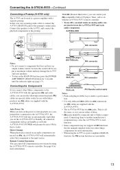
... indicator lights up (page 17). Auto Power On When you set to make an analog audio con- See page 8 for more information. connector Remote Interactive Dock, etc. Remote control cable Notes: • Push each audio component. nection between the A-9755/A-9555 and each plug in your -compatible Onkyo CD player, Tuner, and so on the MAIN IN function, press the [POWER AMP DIRECT (MAIN IN)] button for this case, use with Onkyo products (no cables...
... indicator lights up (page 17). Auto Power On When you set to make an analog audio con- See page 8 for more information. connector Remote Interactive Dock, etc. Remote control cable Notes: • Push each audio component. nection between the A-9755/A-9555 and each plug in your -compatible Onkyo CD player, Tuner, and so on the MAIN IN function, press the [POWER AMP DIRECT (MAIN IN)] button for this case, use with Onkyo products (no cables...
Owner Manual
Page 14
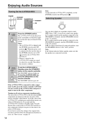
... connected speakers, turn on the other components. Selecting Speaker 1 A-9755/ A-9555 Press the [POWER] switch. The STANDBY indicator goes off the system. A: To output sound from the speakers connected to the "A+B" position. The A-9755/A-9555 retains the power mode (on with just one press of the remote controller's [ON] button. Notes: • The A-9755/A-9555 is set to Standby mode. The STANDBY indicator lights up. You will turn the A-9755/A-9555 on, press the [ON] button on the remote controller. OFF: Select...
... connected speakers, turn on the other components. Selecting Speaker 1 A-9755/ A-9555 Press the [POWER] switch. The STANDBY indicator goes off the system. A: To output sound from the speakers connected to the "A+B" position. The A-9755/A-9555 retains the power mode (on with just one press of the remote controller's [ON] button. Notes: • The A-9755/A-9555 is set to Standby mode. The STANDBY indicator lights up. You will turn the A-9755/A-9555 on, press the [ON] button on the remote controller. OFF: Select...
Owner Manual
Page 15
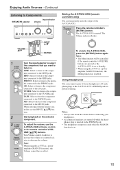
... adjust the volume, use the INPUT [ ]/[ ] buttons. To unmute the A-9755/A-9555, press the [MUTING] button again. Using Headphones You can temporarily mute the output of stereo headphones (1/4-inch phone plug) to the A-9755/A-9555's PHONES jack for private listening. The A-9755/A-9555 is on the selected component. TAPE: Select to hear the component connected to the TUNER jacks. Note: When using the A-9755 as a power amplifier (MAIN IN function), the Volume control has no sound...
... adjust the volume, use the INPUT [ ]/[ ] buttons. To unmute the A-9755/A-9555, press the [MUTING] button again. Using Headphones You can temporarily mute the output of stereo headphones (1/4-inch phone plug) to the A-9755/A-9555's PHONES jack for private listening. The A-9755/A-9555 is on the selected component. TAPE: Select to hear the component connected to the TUNER jacks. Note: When using the A-9755 as a power amplifier (MAIN IN function), the Volume control has no sound...
Owner Manual
Page 16
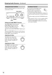
The PURE DIRECT indicator lights up to make them quieter. Turn it down to make them louder. Adjusting the Treble The TREBLE control adjusts treble sounds. ness control is on , the A-9755's tone controls have no effect. Enjoying Audio Sources-Continued Using the Tone Controls While the MAIN IN function is on , the Loud- Normally, it up . PURE DIRECT TREBLE BASS Setting the PURE DIRECT Function The [PURE DIRECT] button turns the PURE DIRECT function on , the tone controls are reinforced when the...
The PURE DIRECT indicator lights up to make them quieter. Turn it down to make them louder. Adjusting the Treble The TREBLE control adjusts treble sounds. ness control is on , the A-9755's tone controls have no effect. Enjoying Audio Sources-Continued Using the Tone Controls While the MAIN IN function is on , the Loud- Normally, it up . PURE DIRECT TREBLE BASS Setting the PURE DIRECT Function The [PURE DIRECT] button turns the PURE DIRECT function on , the tone controls are reinforced when the...
Owner Manual
Page 17
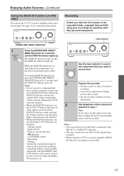
... function off, press the [POWER AMP DIRECT (MAIN IN)] button for more information. 3 Start playback on a recorder that the Volume control is not turned up . function - Notes: • You can record on the component selected in step 1. Notes: • Do not connect a component that does not have an output volume control to the MD OUT or TAPE OUT L/R jacks. • The tone controls have the full consent of these functions including controlling volume, selecting input...
... function off, press the [POWER AMP DIRECT (MAIN IN)] button for more information. 3 Start playback on a recorder that the Volume control is not turned up . function - Notes: • You can record on the component selected in step 1. Notes: • Do not connect a component that does not have an output volume control to the MD OUT or TAPE OUT L/R jacks. • The tone controls have the full consent of these functions including controlling volume, selecting input...
Owner Manual
Page 18
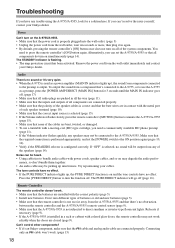
... the inputs and outputs of all components do turn the function off (page 16). If you have no obstruction between the remote controller and the A-9755/A-9555's remote control sensor (page 9). • Make sure that the only an cable won't work. (page 13) cable and analog audio cable are installed with power cords, speaker cables, and so on may not be picking up , the PURE DIRECT function is on and the tone controls have any speakers...
... the inputs and outputs of all components do turn the function off (page 16). If you have no obstruction between the remote controller and the A-9755/A-9555's remote control sensor (page 9). • Make sure that the only an cable won't work. (page 13) cable and analog audio cable are installed with power cords, speaker cables, and so on may not be picking up , the PURE DIRECT function is on and the tone controls have any speakers...
Owner Manual
Page 19
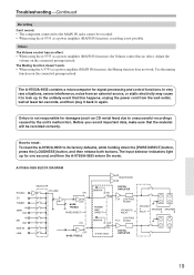
... for signal processing and control functions. A-9755/A-9555 BLOCK DIAGRAM PHONO CD TUNER IN TAPE OUT IN MD OUT HDD IN LINE HEADPHONE SELECTOR VOLUME ON OFF BASS, TREBLE PURE DIRECT ON OFF BASS, TREBLE MAIN IN ON OFF DIGITAL AMPLIFIER L-ch LOW PASS FILTER POWER AMP DIRECT SPEAKER B RELAY MAIN IN ON OFF A-9755 ONLY LOW PASS R-ch FILTER DIGITAL AMPLIFIER SPEAKER A SPEAKER SPEAKER RELAY A B 19 The input selector indicators light up . The Muting function doesn't work. • When using the...
... for signal processing and control functions. A-9755/A-9555 BLOCK DIAGRAM PHONO CD TUNER IN TAPE OUT IN MD OUT HDD IN LINE HEADPHONE SELECTOR VOLUME ON OFF BASS, TREBLE PURE DIRECT ON OFF BASS, TREBLE MAIN IN ON OFF DIGITAL AMPLIFIER L-ch LOW PASS FILTER POWER AMP DIRECT SPEAKER B RELAY MAIN IN ON OFF A-9755 ONLY LOW PASS R-ch FILTER DIGITAL AMPLIFIER SPEAKER A SPEAKER SPEAKER RELAY A B 19 The input selector indicators light up . The Muting function doesn't work. • When using the...
Owner Manual
Page 20
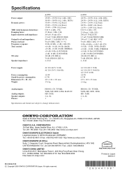
Specifications Power output: Dynamic power: THD (total harmonic distortion): Damping factor: Input sensitivity and impedance: Output level and impedance: Phono overload: Frequency response: Tone control: SN ratio: Speaker impedance: A-9755 150 W + 150 W (8 Ω, 1 kHz, DIN) 300 W + 300 W (4 Ω, 1 kHz, JEITA) 330 W + ...Analog inputs: Analog outputs: Speaker outputs: Phones: PHONO, CD, TUNER, TAPE, MD, HDD, LINE, MAIN IN MD, TAPE 2 (A, B) 1 Specifications and features are subject to change without notice. Tel: 201-785-2600 Fax: 201-785-2650 http://www.us.onkyo.com/ ONKYO...
Specifications Power output: Dynamic power: THD (total harmonic distortion): Damping factor: Input sensitivity and impedance: Output level and impedance: Phono overload: Frequency response: Tone control: SN ratio: Speaker impedance: A-9755 150 W + 150 W (8 Ω, 1 kHz, DIN) 300 W + 300 W (4 Ω, 1 kHz, JEITA) 330 W + ...Analog inputs: Analog outputs: Speaker outputs: Phones: PHONO, CD, TUNER, TAPE, MD, HDD, LINE, MAIN IN MD, TAPE 2 (A, B) 1 Specifications and features are subject to change without notice. Tel: 201-785-2600 Fax: 201-785-2650 http://www.us.onkyo.com/ ONKYO...


