
Service Manual
Page 2
...of Contents Service Guide OL1200 0 About This Manual Front Cover 1 Configuration 1. Configuration 1.2 Printer Configuration 1.3 Optional Configuration 1.4 Specification 1.5 Safety Standards ....1.5.2 Warning Label 2 Operation Description 2. Parts Replacement 3.1 Precautions For Parts Replacement ........[Service Tools] 3.2 Parts Layout 1- 4 ....Parts Layout 2 - 4 ....Parts Layout 3 - 4 ....Parts Layout 4 - 4 3.3 How To Change Parts ....3.3.1 Rear Cover, ... 2.5 Paper Jam Detection 2.6 Cover Open 2.7 Toner Low Detection 2.8 Stacker-Full Detection 2.9 Page Size Detection 3 Parts Replacement 3.
...of Contents Service Guide OL1200 0 About This Manual Front Cover 1 Configuration 1. Configuration 1.2 Printer Configuration 1.3 Optional Configuration 1.4 Specification 1.5 Safety Standards ....1.5.2 Warning Label 2 Operation Description 2. Parts Replacement 3.1 Precautions For Parts Replacement ........[Service Tools] 3.2 Parts Layout 1- 4 ....Parts Layout 2 - 4 ....Parts Layout 3 - 4 ....Parts Layout 4 - 4 3.3 How To Change Parts ....3.3.1 Rear Cover, ... 2.5 Paper Jam Detection 2.6 Cover Open 2.7 Toner Low Detection 2.8 Stacker-Full Detection 2.9 Page Size Detection 3 Parts Replacement 3.

Service Manual
Page 4
...or I /F time-out occurs between printer and optinal tray (ERROR 81) ........6. Communications with the host cannot be received through the OKI HSP interface 112 ....6.5.3 Image troubleshooting 113 ........1. General Information 89 6 Troubleshooting Procedures 6.1 Troubleshooting Tips 90 6.2 Points to Check before Correcting ... in the vertical direction 116 ........5. Table of Contents Page 4.2 Adjustment When Replacing A Part 81 ....4.2.1 Setting of LED head drive time 82 ....4.2.2 Resetting the fuser counter 83 ....4.2.3 Destination setting 84 5 Periodic Maintenance 5.1...
...or I /F time-out occurs between printer and optinal tray (ERROR 81) ........6. Communications with the host cannot be received through the OKI HSP interface 112 ....6.5.3 Image troubleshooting 113 ........1. General Information 89 6 Troubleshooting Procedures 6.1 Troubleshooting Tips 90 6.2 Points to Check before Correcting ... in the vertical direction 116 ........5. Table of Contents Page 4.2 Adjustment When Replacing A Part 81 ....4.2.1 Setting of LED head drive time 82 ....4.2.2 Resetting the fuser counter 83 ....4.2.3 Destination setting 84 5 Periodic Maintenance 5.1...

Service Manual
Page 5
...vertical direction 7 Wiring Diagram 7.1 Wiring Diagram 7.2 PCB Layout 7.3 Resistance Check 7.4 Short Plug Setting 8 Parts List 8. Parts Replacement ....3.2 Parts Layout ....3.3 Parts Replacement Methods ........3.3.1 Idle rollers ........3.3.2 AOLT-PCB ........3.3.3 Hopping motor ........3.3.4 Feed roller ........3.3.5 Hopping roller rubber ... ....4.3 Troubleshooting Method ........4.3.1 LCD Status Message List ........4.3.2 Troubleshooting Flow 5. Connection Diagram ....5.2 PCB Layout 6. Parts List Main Chassis Unit Front Feeder Unit Base Unit A RS-232 Serial Interface Rs-232 Serial Interface...
...vertical direction 7 Wiring Diagram 7.1 Wiring Diagram 7.2 PCB Layout 7.3 Resistance Check 7.4 Short Plug Setting 8 Parts List 8. Parts Replacement ....3.2 Parts Layout ....3.3 Parts Replacement Methods ........3.3.1 Idle rollers ........3.3.2 AOLT-PCB ........3.3.3 Hopping motor ........3.3.4 Feed roller ........3.3.5 Hopping roller rubber ... ....4.3 Troubleshooting Method ........4.3.1 LCD Status Message List ........4.3.2 Troubleshooting Flow 5. Connection Diagram ....5.2 PCB Layout 6. Parts List Main Chassis Unit Front Feeder Unit Base Unit A RS-232 Serial Interface Rs-232 Serial Interface...

Service Manual
Page 6
Parts List Page 156 157 158 159 160 161 162 163 164 165 166 167 168 169 170 171 172 Table of Contents ....2.2 Hopper Mechanism 3. Parts Replacement ....3.2 Parts Layout ....3.3 Parts Replacement Methods ........3.3.1 Separator ........3.3.2 AOLE-PCB ........3.3.3 Square-shaped connector ........3.3.4 Hopping Motor ........3.3.5 Planet gear ........3.3.6 Roller B ........3.3.7 Roller A ........3.3.8 Mini pitch belt & Feed roller 4. Troubleshooting ........4.3.2 Troubleshooting Flow 5. Connection Diagram ....5.2 PCB Layout 6.
Parts List Page 156 157 158 159 160 161 162 163 164 165 166 167 168 169 170 171 172 Table of Contents ....2.2 Hopper Mechanism 3. Parts Replacement ....3.2 Parts Layout ....3.3 Parts Replacement Methods ........3.3.1 Separator ........3.3.2 AOLE-PCB ........3.3.3 Square-shaped connector ........3.3.4 Hopping Motor ........3.3.5 Planet gear ........3.3.6 Roller B ........3.3.7 Roller A ........3.3.8 Mini pitch belt & Feed roller 4. Troubleshooting ........4.3.2 Troubleshooting Flow 5. Connection Diagram ....5.2 PCB Layout 6.

Service Manual
Page 23
Supervises the paper running time. ON: Paper exists. ON: A4 or larger OFF: Smaller than A4 Detects the leading part of paper. ON: Paper exists. Supervises the paper running state and the paper size according to the paper reach time and running ...supervises the paper running state during printing. Sensor Inlet sensor 1 Inlet sensor 2 Paper sensor Outlet sensor Paper end sensor Function Sensing state Detects the leading part of the paper. ON: Paper exists. OFF: No paper exists. OFF: No paper exists. Figure 2-3 shows the sensor layout diagram. Detects the form...
Supervises the paper running time. ON: Paper exists. ON: A4 or larger OFF: Smaller than A4 Detects the leading part of paper. ON: Paper exists. Supervises the paper running state and the paper size according to the paper reach time and running ...supervises the paper running state during printing. Sensor Inlet sensor 1 Inlet sensor 2 Paper sensor Outlet sensor Paper end sensor Function Sensing state Detects the leading part of the paper. ON: Paper exists. OFF: No paper exists. OFF: No paper exists. Figure 2-3 shows the sensor layout diagram. Detects the form...
Service Manual
Page 28
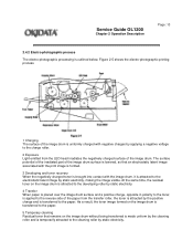
... 3 Developing and toner recovery When the negatively charged toner is brought into contact with negative charges by static electricity. Service Guide OL1200 Chapter 2 Operation Description Page: 13 2.4.2 Electro-photographic process The electro-photographic processing is attracted to the electrostatic latent image by ...static electricity, making the image visible. The surface potential of the irradiated part of the image drum. As a result, the toner image formed on the image drum without being transferred is made uniform...
... 3 Developing and toner recovery When the negatively charged toner is brought into contact with negative charges by static electricity. Service Guide OL1200 Chapter 2 Operation Description Page: 13 2.4.2 Electro-photographic process The electro-photographic processing is attracted to the electrostatic latent image by ...static electricity, making the image visible. The surface potential of the irradiated part of the image drum. As a result, the toner image formed on the image drum without being transferred is made uniform...
Service Manual
Page 35
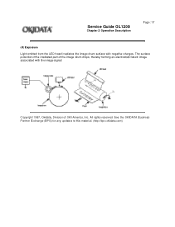
The surface potential of the irradiated part of OKI America, Inc. Service Guide OL1200 Chapter 2 Operation Description Page: 17 (4) Exposure Light emitted from the LED head irradiates the image drum surface with the image signal. Copyright 1997, Okidata, Division of the image drum drops, thereby forming an electrostatic latent image associated with negative charges. See the OKIDATA Business Partner Exchange (BPX) for any updates to this material. (http://bpx.okidata.com) All rights reserved.
The surface potential of the irradiated part of OKI America, Inc. Service Guide OL1200 Chapter 2 Operation Description Page: 17 (4) Exposure Light emitted from the LED head irradiates the image drum surface with the image signal. Copyright 1997, Okidata, Division of the image drum drops, thereby forming an electrostatic latent image associated with negative charges. See the OKIDATA Business Partner Exchange (BPX) for any updates to this material. (http://bpx.okidata.com) All rights reserved.
Service Manual
Page 36
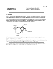
...toner, allowing the toner to be attracted to the developing roller. (The developing roller surface is attracted to the exposed part (low-potential part) of the image drum at the contact between the image drum and the developing roller, making the electrostatic latent image ...visible. Service Guide OL1200 Chapter 2 Operation Description Page: 18 (5) Developing Toner is scraped off by the doctor blade, forming a thin coat of toner on the developing roller surface. 3. Copyright 1997, Okidata, Division of OKI America, Inc. Developing takes place at the...
...toner, allowing the toner to be attracted to the developing roller. (The developing roller surface is attracted to the exposed part (low-potential part) of the image drum at the contact between the image drum and the developing roller, making the electrostatic latent image ...visible. Service Guide OL1200 Chapter 2 Operation Description Page: 18 (5) Developing Toner is scraped off by the doctor blade, forming a thin coat of toner on the developing roller surface. 3. Copyright 1997, Okidata, Division of OKI America, Inc. Developing takes place at the...

Service Manual
Page 41
... the paper does not pass over the outlet sensor within a predetermined time after the paper has reached the inlet sensor. - The leading part of the paper does not reach the paper sensor within a predetermined distance after the paper has reached the paper sensor. - If any ... has reached the outlet sensor. - The paper does not pass over the paper sensor within a predetermined distance after the leading part of error - Service Guide OL1200 Chapter 2 Operation Description Page: 23 2.5 Paper Jam Detection The paper jam detection function supervises the paper state at power-on ...
... the paper does not pass over the outlet sensor within a predetermined time after the paper has reached the inlet sensor. - The leading part of the paper does not reach the paper sensor within a predetermined distance after the paper has reached the paper sensor. - If any ... has reached the outlet sensor. - The paper does not pass over the paper sensor within a predetermined distance after the leading part of error - Service Guide OL1200 Chapter 2 Operation Description Page: 23 2.5 Paper Jam Detection The paper jam detection function supervises the paper state at power-on ...

Service Manual
Page 48
Service Guide OL1200 Chapter 3 Parts Replacement Page: 28 3. Only the removal procedures are explained here. Reverse the procedure for any updates to this material. (http://bpx.okidata.com) All rights reserved. See the OKIDATA Business Partner Exchange (BPX) for the installation. Copyright 1997, Okidata, Division of parts, assemblies, and units in the field. PARTS REPLACEMENT The section explains the procedures for replacement of OKI America, Inc.
Service Guide OL1200 Chapter 3 Parts Replacement Page: 28 3. Only the removal procedures are explained here. Reverse the procedure for any updates to this material. (http://bpx.okidata.com) All rights reserved. See the OKIDATA Business Partner Exchange (BPX) for the installation. Copyright 1997, Okidata, Division of parts, assemblies, and units in the field. PARTS REPLACEMENT The section explains the procedures for replacement of OKI America, Inc.

Service Manual
Page 49
...temporarily be attached to the original positions. (7) When handling ICs such as the printer is operating normally. (3) Do not remove unnecessary parts: try disassembly as long as microprocessors, ROM and RAM, and circuit boards, always practice good anti-static procedures. (8) Do not ...place printed circuit boards directly on ("l") the power switch of OKI America, Inc. i) Connect the AC cable and interface cable to the AC receptacle. Service Guide OL1200 Chapter 3 Parts Replacement Page: 29 3.1 Precautions for any updates to this material. (http://bpx.okidata...
...temporarily be attached to the original positions. (7) When handling ICs such as the printer is operating normally. (3) Do not remove unnecessary parts: try disassembly as long as microprocessors, ROM and RAM, and circuit boards, always practice good anti-static procedures. (8) Do not ...place printed circuit boards directly on ("l") the power switch of OKI America, Inc. i) Connect the AC cable and interface cable to the AC receptacle. Service Guide OL1200 Chapter 3 Parts Replacement Page: 29 3.1 Precautions for any updates to this material. (http://bpx.okidata...

Service Manual
Page 50
See the OKIDATA Business Partner Exchange (BPX) for field replacement of OKI America, Inc. Service Guide OL1200 Chapter 3 Parts Replacement Page: 30 [Service Tools] Table 3-1 shows the tools required for any updates to this material. (http://bpx.okidata.com) All rights reserved. Table 3-1 Service Tools Copyright 1997, Okidata, Division of printed circuit boards and units.
See the OKIDATA Business Partner Exchange (BPX) for field replacement of OKI America, Inc. Service Guide OL1200 Chapter 3 Parts Replacement Page: 30 [Service Tools] Table 3-1 shows the tools required for any updates to this material. (http://bpx.okidata.com) All rights reserved. Table 3-1 Service Tools Copyright 1997, Okidata, Division of printed circuit boards and units.

Service Manual
Page 51
See the OKIDATA Business Partner Exchange (BPX) for any updates to this material. (http://bpx.okidata.com) All rights reserved. 3.2 Parts Layout 1 - 4 Service Guide OL1200 Chapter 3 Parts Replacement Page: 31 Copyright 1997, Okidata, Division of OKI America, Inc.
See the OKIDATA Business Partner Exchange (BPX) for any updates to this material. (http://bpx.okidata.com) All rights reserved. 3.2 Parts Layout 1 - 4 Service Guide OL1200 Chapter 3 Parts Replacement Page: 31 Copyright 1997, Okidata, Division of OKI America, Inc.

Service Manual
Page 52
Parts Layout 2 - 4 Service Guide OL1200 Chapter 3 Parts Replacement Page: 32 Copyright 1997, Okidata, Division of OKI America, Inc. See the OKIDATA Business Partner Exchange (BPX) for any updates to this material. (http://bpx.okidata.com) All rights reserved.
Parts Layout 2 - 4 Service Guide OL1200 Chapter 3 Parts Replacement Page: 32 Copyright 1997, Okidata, Division of OKI America, Inc. See the OKIDATA Business Partner Exchange (BPX) for any updates to this material. (http://bpx.okidata.com) All rights reserved.

Service Manual
Page 53
See the OKIDATA Business Partner Exchange (BPX) for any updates to this material. (http://bpx.okidata.com) All rights reserved. Parts Layout 3 - 4 Service Guide OL1200 Chapter 3 Parts Replacement Page: 33 Copyright 1997, Okidata, Division of OKI America, Inc.
See the OKIDATA Business Partner Exchange (BPX) for any updates to this material. (http://bpx.okidata.com) All rights reserved. Parts Layout 3 - 4 Service Guide OL1200 Chapter 3 Parts Replacement Page: 33 Copyright 1997, Okidata, Division of OKI America, Inc.

Service Manual
Page 54
See the OKIDATA Business Partner Exchange (BPX) for any updates to this material. (http://bpx.okidata.com) Parts Layout 4 - 4 Service Guide OL1200 Chapter 3 Parts Replacement Page: 34 Copyright 1997, Okidata, Division of OKI America, Inc. All rights reserved.
See the OKIDATA Business Partner Exchange (BPX) for any updates to this material. (http://bpx.okidata.com) Parts Layout 4 - 4 Service Guide OL1200 Chapter 3 Parts Replacement Page: 34 Copyright 1997, Okidata, Division of OKI America, Inc. All rights reserved.

Service Manual
Page 55
Service Guide OL1200 Chapter 3 Parts Replacement Page: 35 3.3 How to Change Parts This section explains how to this material. (http://bpx.okidata.com) See the OKIDATA Business Partner Exchange (BPX) for any updates to change parts and assemblies appearing in the disassembly diagram below. Copyright 1997, Okidata, Division of OKI America, Inc. All rights reserved.
Service Guide OL1200 Chapter 3 Parts Replacement Page: 35 3.3 How to Change Parts This section explains how to this material. (http://bpx.okidata.com) See the OKIDATA Business Partner Exchange (BPX) for any updates to change parts and assemblies appearing in the disassembly diagram below. Copyright 1997, Okidata, Division of OKI America, Inc. All rights reserved.
Service Manual
Page 56
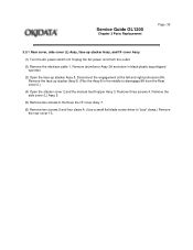
... and right protrusions 8A . Unplug the AC power cord from the Rear cover 0.) (4) Open the stacker cover 2 and the manual feed hopper Assy 3. Service Guide OL1200 Chapter 3 Parts Replacement Page: 36 3.3.1 Rear cover, side cover (L) Assy, face-up stacker Assy 8. Remove the face-up stacker Assy 8. (Flex the Assy 8 in black plastic...
... and right protrusions 8A . Unplug the AC power cord from the Rear cover 0.) (4) Open the stacker cover 2 and the manual feed hopper Assy 3. Service Guide OL1200 Chapter 3 Parts Replacement Page: 36 3.3.1 Rear cover, side cover (L) Assy, face-up stacker Assy 8. Remove the face-up stacker Assy 8. (Flex the Assy 8 in black plastic...

Service Manual
Page 58
Remove the contact plate (cover) 2 and the contact Assy 3. Service Guide OL1200 Chapter 3 Parts Replacement Page: 37 3.3.2 Contact Assy (1) Turn the AC power switch off. See the OKIDATA Business Partner Exchange (BPX) for any updates to deform the electrodes ...of the contact Assy when removing the contact Assy. Pull bottom of Assy 3 out first, then the top of OKI America, Inc. Copyright 1997, Okidata, ...
Remove the contact plate (cover) 2 and the contact Assy 3. Service Guide OL1200 Chapter 3 Parts Replacement Page: 37 3.3.2 Contact Assy (1) Turn the AC power switch off. See the OKIDATA Business Partner Exchange (BPX) for any updates to deform the electrodes ...of the contact Assy when removing the contact Assy. Pull bottom of Assy 3 out first, then the top of OKI America, Inc. Copyright 1997, Okidata, ...

Service Manual
Page 59
Unplug the AC power cord from the outlet. (2) Remove the side cover (L) Assy (see 3.3.1 (1) to this material. (http://bpx.okidata.com) See the OKIDATA Business Partner Exchange (BPX) for any updates to (4)). (3) Unplug the connector of OKI America, Inc. All rights reserved. Copyright 1997, Okidata, Division of the DC fan motor 1 and remove the DC fan motor 1. Service Guide OL1200 Chapter 3 Parts Replacement Page: 38 3.3.3 DC fan motor (1) Turn the AC power switch off.
Unplug the AC power cord from the outlet. (2) Remove the side cover (L) Assy (see 3.3.1 (1) to this material. (http://bpx.okidata.com) See the OKIDATA Business Partner Exchange (BPX) for any updates to (4)). (3) Unplug the connector of OKI America, Inc. All rights reserved. Copyright 1997, Okidata, Division of the DC fan motor 1 and remove the DC fan motor 1. Service Guide OL1200 Chapter 3 Parts Replacement Page: 38 3.3.3 DC fan motor (1) Turn the AC power switch off.


