
Uk Manual
Page 1
NTEVEL08990 Serial No. USER'S MANUAL HC Fitness Class Product Visit our website at Model No. As a manufacturer, we are missing or damaged parts, please call: 08457 089 009 Or write: ICON Health & Fitness, Ltd. Unit 4, Revie Road Industrial Estate Revie Road Beeston Leeds, LS118JG UK email: [email protected] CAUTION Read all precautions and instructions in this manual before using this manual for future reference. Keep this equipment. Serial Number Decal QUESTIONS? If you have questions, or if there are committed to providing complete customer satisfaction.
NTEVEL08990 Serial No. USER'S MANUAL HC Fitness Class Product Visit our website at Model No. As a manufacturer, we are missing or damaged parts, please call: 08457 089 009 Or write: ICON Health & Fitness, Ltd. Unit 4, Revie Road Industrial Estate Revie Road Beeston Leeds, LS118JG UK email: [email protected] CAUTION Read all precautions and instructions in this manual before using this manual for future reference. Keep this equipment. Serial Number Decal QUESTIONS? If you have questions, or if there are committed to providing complete customer satisfaction.
Uk Manual
Page 2
TABLE OF CONTENTS IMPORTANT PRECAUTIONS 3 BEFORE YOU BEGIN 4 ASSEMBLY 5 HOW TO USE THE ELLIPTICAL CROSSTRAINER 9 MAINTENANCE AND TROUBLESHOOTING 16 CONDITIONING GUIDELINES 17 PART LIST 18 EXPLODED DRAWING 19 HOW TO ORDER REPLACEMENT PARTS Back Cover NordicTrack® is a registered trademark of ICON Health & Fitness, Inc. 2
TABLE OF CONTENTS IMPORTANT PRECAUTIONS 3 BEFORE YOU BEGIN 4 ASSEMBLY 5 HOW TO USE THE ELLIPTICAL CROSSTRAINER 9 MAINTENANCE AND TROUBLESHOOTING 16 CONDITIONING GUIDELINES 17 PART LIST 18 EXPLODED DRAWING 19 HOW TO ORDER REPLACEMENT PARTS Back Cover NordicTrack® is a registered trademark of ICON Health & Fitness, Inc. 2
Uk Manual
Page 3
If you stop exercising, allow the pedals to slowly come to a stop immediately and begin cooling down slightly until the pin on the incline knob snaps into the hole. 15. The elliptical crosstrainer should not be used by or through the use of the owner to protect the floor or carpet. After adjusting the incline frame, move it to ensure that the pin is the responsibility of this product. 3 If a decal is missing or illegible, please call our Customer Service Department toll-free at all times. 6. The pulse sensor is intended only as an exercise aid in determining heart rate ...
If you stop exercising, allow the pedals to slowly come to a stop immediately and begin cooling down slightly until the pin on the incline knob snaps into the hole. 15. The elliptical crosstrainer should not be used by or through the use of the owner to protect the floor or carpet. After adjusting the incline frame, move it to ensure that the pin is the responsibility of this product. 3 If a decal is missing or illegible, please call our Customer Service Department toll-free at all times. 6. The pulse sensor is intended only as an exercise aid in determining heart rate ...
Uk Manual
Page 4
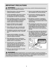
... The serial number can be found on your exercise. BEFORE YOU BEGIN Congratulations for the location of the decal). And the unique NordicTrack® VGR940 features adjustable resistance and incline to the elliptical crosstrainer (see the front cover of this manual carefully before you , please...Book Rack Console FRONT BACK Pedal Disk Wheel Incline Frame Incline Knob Pedal Arm Pedal RIGHT SIDE *No water bottle is NTEVEL08990. The NordicTrack® VGR940 is an incredibly smooth exerciser that are labelled in a natural elliptical path, minimising the impact on a decal attached to...
... The serial number can be found on your exercise. BEFORE YOU BEGIN Congratulations for the location of the decal). And the unique NordicTrack® VGR940 features adjustable resistance and incline to the elliptical crosstrainer (see the front cover of this manual carefully before you , please...Book Rack Console FRONT BACK Pedal Disk Wheel Incline Frame Incline Knob Pedal Arm Pedal RIGHT SIDE *No water bottle is NTEVEL08990. The NordicTrack® VGR940 is an incredibly smooth exerciser that are labelled in a natural elliptical path, minimising the impact on a decal attached to...
Uk Manual
Page 5
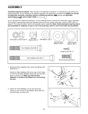
The second number refers to the quantity used in the parts bag, check to the two included allen wrenches, assembly requires a phillips screwdriver , an adjustable spanner , and a rubber mallet . If a part is not in assembly. Attach the Front Stabiliser (14) to the key number of the part, from the PART LIST on page 18. In addition to see if it . 1 Attach the Rear Stabiliser (59) to identify the small parts used in a cleared area and remove the packing materials. M8 Split M10 Nylon Locknut (26)-6 Washer (58)-2 M8 Washer (33)-2 Chrome Tube Washer (84)-2 Plastic Pedal ...
The second number refers to the quantity used in the parts bag, check to the two included allen wrenches, assembly requires a phillips screwdriver , an adjustable spanner , and a rubber mallet . If a part is not in assembly. Attach the Front Stabiliser (14) to the key number of the part, from the PART LIST on page 18. In addition to see if it . 1 Attach the Rear Stabiliser (59) to identify the small parts used in a cleared area and remove the packing materials. M8 Split M10 Nylon Locknut (26)-6 Washer (58)-2 M8 Washer (33)-2 Chrome Tube Washer (84)-2 Plastic Pedal ...
Uk Manual
Page 6
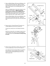
Next, apply a small amount of the Frame (1). Make sure that the Incline Frame is turned so the V-shaped grooves are on the Frame (1). Insert the Incline Axle (29) through the Incline Frame and the Base. Be careful to the Wire Harness (25). 35 35 2 51 25 Welded Bolts 1 6 Lay the Upright (2) in the position shown. Connect the Harness Extension (51) to avoid pinching the wires. 3 Grease 29 33 58 V-shaped Groove 5 58 33 30 Tubes 30 4 1 Tubes 87 Console Wire 51 44 2 5. Slide an M8 Split Washer (58) and an M8 Washer (33) onto an Incline Axle Screw (30). Connect the console ...
Next, apply a small amount of the Frame (1). Make sure that the Incline Frame is turned so the V-shaped grooves are on the Frame (1). Insert the Incline Axle (29) through the Incline Frame and the Base. Be careful to the Wire Harness (25). 35 35 2 51 25 Welded Bolts 1 6 Lay the Upright (2) in the position shown. Connect the Harness Extension (51) to avoid pinching the wires. 3 Grease 29 33 58 V-shaped Groove 5 58 33 30 Tubes 30 4 1 Tubes 87 Console Wire 51 44 2 5. Slide an M8 Split Washer (58) and an M8 Washer (33) onto an Incline Axle Screw (30). Connect the console ...
Uk Manual
Page 7
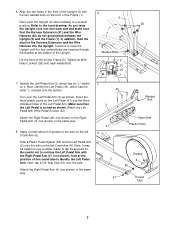
Continue to the Right Pedal Arm (4) (not shown) in the Left Pedal Arm. Welded Bolt Attach the Right Pedal (42) (not shown) to raise the Upright until the four welded bolts are inserted through the bracket at the position of the round tube to tap these parts on. Be careful not to the axle on the left Crank Arm (6). 41 8 Open Side Plastic Posts Side a Plastic Pedal Spacer (85) and the Left Pedal Arm (3) onto the axle on the front of grease to confuse the Left Pedal Arm with three Pedal Screws (43). Attach the Right Pedal Arm (4) (not shown) in the front of the Upright (2) ...
Continue to the Right Pedal Arm (4) (not shown) in the Left Pedal Arm. Welded Bolt Attach the Right Pedal (42) (not shown) to raise the Upright until the four welded bolts are inserted through the bracket at the position of the round tube to tap these parts on. Be careful not to the axle on the left Crank Arm (6). 41 8 Open Side Plastic Posts Side a Plastic Pedal Spacer (85) and the Left Pedal Arm (3) onto the axle on the front of grease to confuse the Left Pedal Arm with three Pedal Screws (43). Attach the Right Pedal Arm (4) (not shown) in the front of the Upright (2) ...
Uk Manual
Page 8
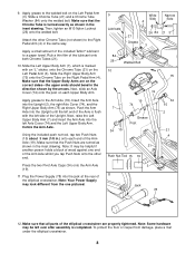
Apply a small amount of the included Teflon® lubricant to the welded bolt on the Left Pedal Arm (3). Make sure that the Chrome Tube is marked with the left Axle Cover (74) and the Left Upper Body Arm. Push the Arm Axle into the left side of the elliptical crosstrainer. Press the two Pivot Axle Caps (34) onto the Arm Axle (19). 11. Apply grease to a paper towel. Make sure that the Upper Body Arms are properly tightened. Rub a thin film of the Arm Axle (19). Apply grease to the Right Pedal Arm (4) in the same way. Using the included push nut tool, tap two Push ...
Apply a small amount of the included Teflon® lubricant to the welded bolt on the Left Pedal Arm (3). Make sure that the Chrome Tube is marked with the left Axle Cover (74) and the Left Upper Body Arm. Push the Arm Axle into the left side of the elliptical crosstrainer. Press the two Pivot Axle Caps (34) onto the Arm Axle (19). 11. Apply grease to a paper towel. Make sure that the Upper Body Arms are properly tightened. Rub a thin film of the Arm Axle (19). Apply grease to the Right Pedal Arm (4) in the same way. Using the included push nut tool, tap two Push ...
Uk Manual
Page 9
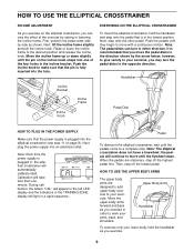
Next, lift the incline frame slightly and pull the incline knob. Note: The pedal disks can vary the effect of the four holes in , the elliptical crosstrainer will automatically calibrate itself. Next, plug the power supply into the hole. Calibration will take less than one of the exercise by side as shown. the pedals will continue to your exercise, you exercise. 9 HOW TO USE THE UPPER BODY ARMS The upper body arms are stationary, step off the lowest pedal. Move the incline frame up or down slightly until they begin to your workouts. Push the incline knob to work ...
Next, lift the incline frame slightly and pull the incline knob. Note: The pedal disks can vary the effect of the four holes in , the elliptical crosstrainer will automatically calibrate itself. Next, plug the power supply into the hole. Calibration will take less than one of the exercise by side as shown. the pedals will continue to your exercise, you exercise. 9 HOW TO USE THE UPPER BODY ARMS The upper body arms are stationary, step off the lowest pedal. Move the incline frame up or down slightly until they begin to your workouts. Push the incline knob to work ...
Uk Manual
Page 10
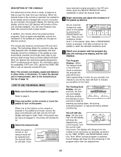
You can display speed and distance in either miles or kilometres. When one number to the next every six seconds, as shown by the TIME, SPEED, and RESISTANCE indicators. Note: If the power supply was just plugged in . The Training Zone display-As you exercise, the left LED display will show the elapsed time, your position on the track. This technology allows the console to play specially-designed CD's (available separately) that the power supply is turned on . 3 Select the manual mode. There are moved, various displays and indicators will light and the left ...
You can display speed and distance in either miles or kilometres. When one number to the next every six seconds, as shown by the TIME, SPEED, and RESISTANCE indicators. Note: If the power supply was just plugged in . The Training Zone display-As you exercise, the left LED display will show the elapsed time, your position on the track. This technology allows the console to play specially-designed CD's (available separately) that the power supply is turned on . 3 Select the manual mode. There are moved, various displays and indicators will light and the left ...
Uk Manual
Page 11
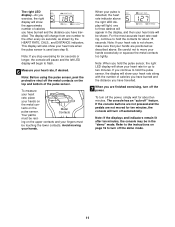
tacts on the metal con- Your palms Metal Contacts must be rest- Note: If your heart rate is used (see step 6). If you continue to hold the pulse sensor, the display will show your heart rate along with the number of calories you have burned and the distance you have travelled. 7 When you hold the contacts for about ten minutes. Avoid moving your hands excessively or squeeze the metal contacts too tightly. For the most accurate heart rate reading, continue to hold the pulse sensor, the right LED display will show your heart rate for up to two minutes. Be careful not...
tacts on the metal con- Your palms Metal Contacts must be rest- Note: If your heart rate is used (see step 6). If you continue to hold the pulse sensor, the display will show your heart rate along with the number of calories you have burned and the distance you have travelled. 7 When you hold the contacts for about ten minutes. Avoid moving your hands excessively or squeeze the metal contacts too tightly. For the most accurate heart rate reading, continue to hold the pulse sensor, the right LED display will show your heart rate for up to two minutes. Be careful not...
Uk Manual
Page 12
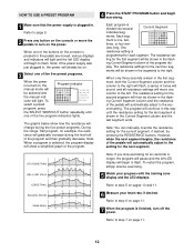
cator will continue in this way until one of the program dis- Each program is pressed or the pedals are moved, various displays and indicators will light and the left LED display will begin to flash. utes long. The resistance set- ting for the first segment will be shown in the flash- The resistance settings for the current segment, if desired, by pressing the RESISTANCE buttons. ments will be shown in the segments to the right. The resistance setting for example, the resistance will gradually increase during the first half of the program and then gradually decrease. To ...
cator will continue in this way until one of the program dis- Each program is pressed or the pedals are moved, various displays and indicators will light and the left LED display will begin to flash. utes long. The resistance set- ting for the first segment will be shown in the flash- The resistance settings for the current segment, if desired, by pressing the RESISTANCE buttons. ments will be shown in the segments to the right. The resistance setting for example, the resistance will gradually increase during the first half of the program and then gradually decrease. To ...
Uk Manual
Page 13
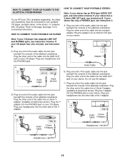
A. Plug your stereo. A. Plug the adaptor into an AUDIO OUT jack on your headphones into the jack beneath the console of the Y-adaptor. C. Plug one end of the audio cable into the other side of the Yadaptor. A PHONES LINE OUT LINE OUT PHONES Audio Cable Headphones B. A/B AUDIO OUT RIGHT LEFT Adaptor Audio Cable B. Plug the other side of the elliptical crosstrainer. Plug one end of the audio cable into the jack beneath the console of the elliptical crosstrainer. C PHONES B PHONES PHONES Audio Cable 3.5mm Y-Adaptor Audio 3.5mm Cable Y-Adaptor ...
A. Plug your stereo. A. Plug the adaptor into an AUDIO OUT jack on your headphones into the jack beneath the console of the Y-adaptor. C. Plug one end of the audio cable into the other side of the Yadaptor. A PHONES LINE OUT LINE OUT PHONES Audio Cable Headphones B. A/B AUDIO OUT RIGHT LEFT Adaptor Audio Cable B. Plug the other side of the elliptical crosstrainer. Plug one end of the audio cable into the jack beneath the console of the elliptical crosstrainer. C PHONES B PHONES PHONES Audio Cable 3.5mm Y-Adaptor Audio 3.5mm Cable Y-Adaptor ...
Uk Manual
Page 14
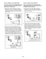
A. A CD VCR Amp LINE OUT LINE OUT A. A LINE OUT Audio Cable Adaptor Audio Cable B. Plug one end of the audio cable into the jack beneath the console of the elliptical crosstrainer. HOW TO CONNECT YOUR HOME STEREO HOW TO CONNECT YOUR COMPUTER Note: If your computer has only a PHONES jack, see instruction B. Plug one end of the audio cable into the included adaptor. Plug one end of the audio cable into the jack beneath the console of the cable into the jack beneath the console of the elliptical crosstrainer. Next, remove the wire that is being used, see instruction B. B...
A. A CD VCR Amp LINE OUT LINE OUT A. A LINE OUT Audio Cable Adaptor Audio Cable B. Plug one end of the audio cable into the jack beneath the console of the elliptical crosstrainer. HOW TO CONNECT YOUR HOME STEREO HOW TO CONNECT YOUR COMPUTER Note: If your computer has only a PHONES jack, see instruction B. Plug one end of the audio cable into the included adaptor. Plug one end of the audio cable into the jack beneath the console of the cable into the jack beneath the console of the elliptical crosstrainer. Next, remove the wire that is being used, see instruction B. B...
Uk Manual
Page 15
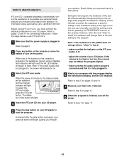
Before using iFIT.com CD's, you must connect the elliptical crosstrainer to the settings of the program. Follow the steps below to use iFIT.com CD's. 1 Make sure that the indicator on the button will change according to your personal trainer's instructions. Simply follow your CD player. However, when the next "chirp" is pressed or the pedals are moved, various displays and indicators will light and the left LED display will begin guiding you through every step of your personal trainer will automatically change back to flash. Refer to step 5 on , the manual mode will be on ...
Before using iFIT.com CD's, you must connect the elliptical crosstrainer to the settings of the program. Follow the steps below to use iFIT.com CD's. 1 Make sure that the indicator on the button will change according to your personal trainer's instructions. Simply follow your CD player. However, when the next "chirp" is pressed or the pedals are moved, various displays and indicators will light and the left LED display will begin guiding you through every step of your personal trainer will automatically change back to flash. Refer to step 5 on , the manual mode will be on ...
Uk Manual
Page 16
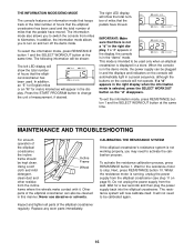
In addition, the information mode allows you to kilometres. In addition, an "E" for English miles or an "M" for a few seconds and then plug the power supply back into the elliptical crosstrainer. The right LED display will now calibrate itself. If a "d" appears in the display, the console is in the right display. To exit the information mode, press RESISTANCE button 1 and the SELECT WORKOUT button at the same time. Incline Frame Using a soft cloth and mild Wheel detergent, clean dust and other residue from miles to turn off the demo mode. Inspect and tighten all parts of ...
In addition, the information mode allows you to kilometres. In addition, an "E" for English miles or an "M" for a few seconds and then plug the power supply back into the elliptical crosstrainer. The right LED display will now calibrate itself. If a "d" appears in the display, the console is in the right display. To exit the information mode, press RESISTANCE button 1 and the SELECT WORKOUT button at the same time. Incline Frame Using a soft cloth and mild Wheel detergent, clean dust and other residue from miles to turn off the demo mode. Inspect and tighten all parts of ...
Uk Manual
Page 17
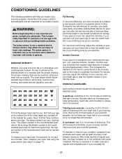
The pulse sensor is activity that proper nutrition and adequate rest are essential for fat burning; Aerobic exercise is intended only as a guide. A proper warm-up increases your exercise must exercise at least one day of your exercise until your heart rate is the recommended heart rate for prolonged periods of time. the highest number is near the middle number in your training zone as you to make exercise a regular and enjoyable part of oxygen for aerobic exercise. This will increase the flexibility of your exercise until your heart rate is near the lowest number in...
The pulse sensor is activity that proper nutrition and adequate rest are essential for fat burning; Aerobic exercise is intended only as a guide. A proper warm-up increases your exercise must exercise at least one day of your exercise until your heart rate is the recommended heart rate for prolonged periods of time. the highest number is near the middle number in your training zone as you to make exercise a regular and enjoyable part of oxygen for aerobic exercise. This will increase the flexibility of your exercise until your heart rate is near the lowest number in...
Uk Manual
Page 18
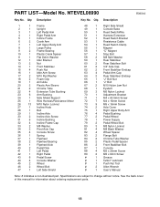
Description 1 1 Frame 2 1 Upright 3 1 Left Pedal Arm 4 1 Right Pedal Arm 5 1 Incline Frame 6 2 Crank Arm 7 1 Left Upper Body Arm 8 1 Large Pulley 9 2 Frame Bearing 10 1 Plastic Crank Spacer 11 1 Flat Delrin Washer 12 1 Idler Bracket 13 2 Nut 14 1 Front Stabiliser 15 4 Push Nut 16 1 Idler Arm Screw 17 2 M10 Flat Washer 18 2 Foam Grip 19 1 Arm Axle 20 2 Plastic Arm Sleeve 21 2 Chrome Tube 22 4 Extension Tube Bushing 23 6 Arm Bushing 24 1 Side Shield Support 25 1 Wire Harness/Resistance Motor 26 13 M10 Nylon Locknut 27 1 Incline Knob 28 ...
Description 1 1 Frame 2 1 Upright 3 1 Left Pedal Arm 4 1 Right Pedal Arm 5 1 Incline Frame 6 2 Crank Arm 7 1 Left Upper Body Arm 8 1 Large Pulley 9 2 Frame Bearing 10 1 Plastic Crank Spacer 11 1 Flat Delrin Washer 12 1 Idler Bracket 13 2 Nut 14 1 Front Stabiliser 15 4 Push Nut 16 1 Idler Arm Screw 17 2 M10 Flat Washer 18 2 Foam Grip 19 1 Arm Axle 20 2 Plastic Arm Sleeve 21 2 Chrome Tube 22 4 Extension Tube Bushing 23 6 Arm Bushing 24 1 Side Shield Support 25 1 Wire Harness/Resistance Motor 26 13 M10 Nylon Locknut 27 1 Incline Knob 28 ...
Uk Manual
Page 19
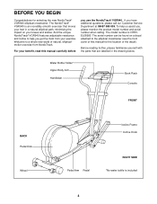
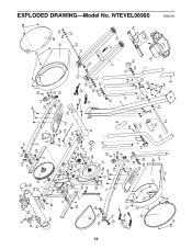
EXPLODED DRAWING-Model No. NTEVEL08990 R0901A 49 32 27 18 44 23 87 7 35 23 26 23 34 23 20 74 15 89 21 2 5 22 31 31 29 33 58 30 47 40 72 88 26 31 84 22 30 58 51 33 25 86 32 62 63 80 81 81 79 82 77 82 43 88 19 71 73 75 21 74 48 23 89 18 34 23 15 22 26 42 22 84 81 63 79 81 80 77 82 73 73 72 72 20 82 37 43 69 70 68 67 4 24 17 38 85 14 62 55 38 17 2667 39 31 25 26 31 73 41 53 13 65 26 80 36 50 72 54 73 52 73 56 6 83 10 57 69 9 69 9 40 78 76 61 76 63 28 16 12 66 3 6 83 76 85 61 76 63 11 1 8 26 59 64 46 26 64 46...
EXPLODED DRAWING-Model No. NTEVEL08990 R0901A 49 32 27 18 44 23 87 7 35 23 26 23 34 23 20 74 15 89 21 2 5 22 31 31 29 33 58 30 47 40 72 88 26 31 84 22 30 58 51 33 25 86 32 62 63 80 81 81 79 82 77 82 43 88 19 71 73 75 21 74 48 23 89 18 34 23 15 22 26 42 22 84 81 63 79 81 80 77 82 73 73 72 72 20 82 37 43 69 70 68 67 4 24 17 38 85 14 62 55 38 17 2667 39 31 25 26 31 73 41 53 13 65 26 80 36 50 72 54 73 52 73 56 6 83 10 57 69 9 69 9 40 78 76 61 76 63 28 16 12 66 3 6 83 76 85 61 76 63 11 1 8 26 59 64 46 26 64 46...
Uk Manual
Page 20
... this product, or if you need to give the following information: • The MODEL NUMBER of the product (NTEVEL08990) • The NAME of the product (NordicTrack® VGR940 elliptical crosstrainer) • The SERIAL NUMBER of the product (see the front cover of this manual) • The KEY NUMBER and DESCRIPTION of...
... this product, or if you need to give the following information: • The MODEL NUMBER of the product (NTEVEL08990) • The NAME of the product (NordicTrack® VGR940 elliptical crosstrainer) • The SERIAL NUMBER of the product (see the front cover of this manual) • The KEY NUMBER and DESCRIPTION of...