Installation Guide
Page 5
...15 1 Overview 17 About the Nokia IP1200 Series Security Platform 17 About the Nokia IP1200 Series Flash-Based Security Platforms 18 Managing the Nokia IP1200 Series Security Platform 19 Nokia IP1200 Series Security Platform Overview 19 Ethernet Management Ports 20 PMC Expansion Slots 21 Console Port 21 System Status LEDs ...28 Site Requirements 28 Safety Warnings and Cautions 28 Software Requirements 30 Product Disposal 30 2 Installing the Nokia IP1200 Series Appliance 33 Rack Mounting the Appliance 33 Before You Begin 34 IP1220 and IP1260 Security Platforms Installation Guide 5
...15 1 Overview 17 About the Nokia IP1200 Series Security Platform 17 About the Nokia IP1200 Series Flash-Based Security Platforms 18 Managing the Nokia IP1200 Series Security Platform 19 Nokia IP1200 Series Security Platform Overview 19 Ethernet Management Ports 20 PMC Expansion Slots 21 Console Port 21 System Status LEDs ...28 Site Requirements 28 Safety Warnings and Cautions 28 Software Requirements 30 Product Disposal 30 2 Installing the Nokia IP1200 Series Appliance 33 Rack Mounting the Appliance 33 Before You Begin 34 IP1220 and IP1260 Security Platforms Installation Guide 5

Installation Guide
Page 6
... Before You Begin 68 Nokia ADP Card LED Reference Information 71 Configuring Nokia IPSO for IP1220 and IP1260 ADP Interfaces 71 Effect on Interfaces 71 Nokia ADP Card Interface Names for IP1220 and IP1260 Appliances 72 Configuration Example with VRRP 73 Deleting VRRP Configurations 74 Reconfiguring Interfaces 75 Reconfiguring VRRP 78 6 IP1220 and IP1260 Security Platforms Installation Guide
... Before You Begin 68 Nokia ADP Card LED Reference Information 71 Configuring Nokia IPSO for IP1220 and IP1260 ADP Interfaces 71 Effect on Interfaces 71 Nokia ADP Card Interface Names for IP1220 and IP1260 Appliances 72 Configuration Example with VRRP 73 Deleting VRRP Configurations 74 Reconfiguring Interfaces 75 Reconfiguring VRRP 78 6 IP1220 and IP1260 Security Platforms Installation Guide

Installation Guide
Page 9
... Locations Front View 20 Figure 2 Ethernet Management Ports Details 20 Figure 3 Pin Assignments for Console and AUX Connections 22 Figure 4 Nokia IP1200 Series Appliance System Status LEDs 23 Figure 5 Hard-Disk Drive Front Pane 24 Figure 6 Power Supply ...DC version 27 Figure 9 Rack-Mounting Screw Locations 34 Figure 10 Power Switch Location 41 Figure 11 Nokia Network Voyager Reference Access Points 45 Figure 12 Four-Port 10/100 Ethernet NIC Front Panel Details 59 ...PC Card Location 88 Figure 23 DIMM Socket Locations 99 IP1220 and IP1260 Security Platforms Installation Guide 9
... Locations Front View 20 Figure 2 Ethernet Management Ports Details 20 Figure 3 Pin Assignments for Console and AUX Connections 22 Figure 4 Nokia IP1200 Series Appliance System Status LEDs 23 Figure 5 Hard-Disk Drive Front Pane 24 Figure 6 Power Supply ...DC version 27 Figure 9 Rack-Mounting Screw Locations 34 Figure 10 Power Switch Location 41 Figure 11 Nokia Network Voyager Reference Access Points 45 Figure 12 Four-Port 10/100 Ethernet NIC Front Panel Details 59 ...PC Card Location 88 Figure 23 DIMM Socket Locations 99 IP1220 and IP1260 Security Platforms Installation Guide 9
Installation Guide
Page 18
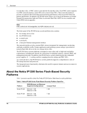
...the Nokia IP1200 Series Flash-Based Security Platforms Table 3 presents specifics about the Nokia IP1200 Series flash-based security platforms. Table 3 Nokia IP1200 Series Flash-Based Security Platform Specifics Platform RAM (Minimum and Maximum Supported Configurations) Compact Flash Nokia IP1220 Minimum: 1 GB Maximum: 2 GB 1 GB Nokia .... As a network device, the IP1200 Series security platform supports a comprehensive suite of the IP1200 Series security platform also contains: „ two storage device slots „ two PCMCIA slots „ a console port „ a serial port „ ...
...the Nokia IP1200 Series Flash-Based Security Platforms Table 3 presents specifics about the Nokia IP1200 Series flash-based security platforms. Table 3 Nokia IP1200 Series Flash-Based Security Platform Specifics Platform RAM (Minimum and Maximum Supported Configurations) Compact Flash Nokia IP1220 Minimum: 1 GB Maximum: 2 GB 1 GB Nokia .... As a network device, the IP1200 Series security platform supports a comprehensive suite of the IP1200 Series security platform also contains: „ two storage device slots „ two PCMCIA slots „ a console port „ a serial port „ ...

Installation Guide
Page 20
.... 1 Overview Figure 1 Component Locations Front View System status LEDs Dual 6U PMC carrier or ADP module expansion slots 1 and 2 hard-disk drive A hard-disk drive B Console port Grounding plug Serial (AUX) port PCMCIA slots 00307a.3 Ethernet management ports (slot 3) Ethernet Management Ports The Ethernet management ports are intended for management purposes... not provide the same performance as Ethernet cards in slot 3. The remaining LEDs represent the remaining ports from top to prevent potential data loss. 20 IP1220 and IP1260 Security Platforms Installation Guide
.... 1 Overview Figure 1 Component Locations Front View System status LEDs Dual 6U PMC carrier or ADP module expansion slots 1 and 2 hard-disk drive A hard-disk drive B Console port Grounding plug Serial (AUX) port PCMCIA slots 00307a.3 Ethernet management ports (slot 3) Ethernet Management Ports The Ethernet management ports are intended for management purposes... not provide the same performance as Ethernet cards in slot 3. The remaining LEDs represent the remaining ports from top to prevent potential data loss. 20 IP1220 and IP1260 Security Platforms Installation Guide
Installation Guide
Page 21
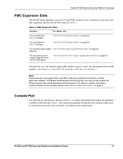
... IP1200 Appliance ADP Services Modules." IP1220 and IP1260 Security Platforms Installation Guide 21 The Nokia Global Support Services group can install a single ADP module in Table 4. For sales or reseller information, contact a Nokia service provider listed in Figure 1, to supply information that use the console port. Console Port Use the built-in console port, shown in the "Nokia Contact...
... IP1200 Appliance ADP Services Modules." IP1220 and IP1260 Security Platforms Installation Guide 21 The Nokia Global Support Services group can install a single ADP module in Table 4. For sales or reseller information, contact a Nokia service provider listed in Figure 1, to supply information that use the console port. Console Port Use the built-in console port, shown in the "Nokia Contact...

Installation Guide
Page 22
...Output 4 DTR Output 5 GND 6 DSR Input 7 RTS Output 8 CTS Input 9 not used Table 5 shows how to match pins at the console or serial connector with output pins on DB9 or DB25 cables you are using with terminal devices or other appropriate equipment. 1 Overview Figure 3 Pin... Assignments for DB9 and DB25 Interface Cables Console or serial DB9 cable output pin and DB25 cable output pin and pin and assignment assignment assignment Shield (FG) Shield (FG) 1 (FG) 2...
...Output 4 DTR Output 5 GND 6 DSR Input 7 RTS Output 8 CTS Input 9 not used Table 5 shows how to match pins at the console or serial connector with output pins on DB9 or DB25 cables you are using with terminal devices or other appropriate equipment. 1 Overview Figure 3 Pin... Assignments for DB9 and DB25 Interface Cables Console or serial DB9 cable output pin and DB25 cable output pin and pin and assignment assignment assignment Shield (FG) Shield (FG) 1 (FG) 2...
Installation Guide
Page 39
... on power to a Nokia IP1200 Series appliance, the initial configuration process begins. You can perform the initial configuration in two ways: „ Configure a DHCP server to provide the initial configuration information the first time the appliance is started. „ Perform the initial configuration manually by using a console connection. IP1220 and IP1260 Security Platforms Installation Guide 39...
... on power to a Nokia IP1200 Series appliance, the initial configuration process begins. You can perform the initial configuration in two ways: „ Configure a DHCP server to provide the initial configuration information the first time the appliance is started. „ Perform the initial configuration manually by using a console connection. IP1220 and IP1260 Security Platforms Installation Guide 39...

Installation Guide
Page 40
...configured with the following settings for the console connection, see "Console Port" on the back of the appliance as shown in Figure 10. 40 IP1220 and IP1260 Security Platforms Installation Guide Connect the supplied null-modem cable (console cable) to the console port on the front panel; the ... on page 21. 2. emulation program. Note The supplied console cable is an auxiliary modem port. 3 Performing the Initial Configuration Using a Console Connection If you do not use DHCP to perform the initial configuration of your Nokia IP1200 Series appliance, you no longer need the...
...configured with the following settings for the console connection, see "Console Port" on the back of the appliance as shown in Figure 10. 40 IP1220 and IP1260 Security Platforms Installation Guide Connect the supplied null-modem cable (console cable) to the console port on the front panel; the ... on page 21. 2. emulation program. Note The supplied console cable is an auxiliary modem port. 3 Performing the Initial Configuration Using a Console Connection If you do not use DHCP to perform the initial configuration of your Nokia IP1200 Series appliance, you no longer need the...
Installation Guide
Page 42
... not illuminate, contact your Nokia IP1200 Series appliance, you do not see the Nokia IPSO Boot Manager Reference Guide. Turn on to enter command mode. If the Hostname? Respond to prevent the DHCP client from starting. 42 IP1220 and IP1260 Security Platforms Installation Guide The prompt...not appear on both ends. If the fans are correct. Note On an appliance with two active power supplies installed, connect and turn on the console, check the console port and console display connections to perform the initial configuration of startup messages appears, then the following...
... not illuminate, contact your Nokia IP1200 Series appliance, you do not see the Nokia IPSO Boot Manager Reference Guide. Turn on to enter command mode. If the Hostname? Respond to prevent the DHCP client from starting. 42 IP1220 and IP1260 Security Platforms Installation Guide The prompt...not appear on both ends. If the fans are correct. Note On an appliance with two active power supplies installed, connect and turn on the console, check the console port and console display connections to perform the initial configuration of startup messages appears, then the following...

Installation Guide
Page 43
...a console connection to prevent the DHCP client from restarting. 3. Enter the following: rm /config/active or mv /config/active /config/active.old d. e. prompt within 30 seconds to the appliance. To... example, the physical ID for the Nokia software release you are prompted to select an interface, Nokia recommends that you can use Nokia Network Voyager to configure the remaining network...two-port Ethernet NIC in the list of the Ethernet management interface ports. IP1220 and IP1260 Security Platforms Installation Guide 43 For more information about its slot number (slot_num), subslot...
...a console connection to prevent the DHCP client from restarting. 3. Enter the following: rm /config/active or mv /config/active /config/active.old d. e. prompt within 30 seconds to the appliance. To... example, the physical ID for the Nokia software release you are prompted to select an interface, Nokia recommends that you can use Nokia Network Voyager to configure the remaining network...two-port Ethernet NIC in the list of the Ethernet management interface ports. IP1220 and IP1260 Security Platforms Installation Guide 43 For more information about its slot number (slot_num), subslot...

Installation Guide
Page 46
... appliance by using a command-line connection (SSH, console, or Telnet) over a TCP/IP network as an admin, cadmin, or monitor user: „ If you log in the CLI Reference Guide for the version of Nokia IPSO you can execute only the show form of commands. Nokia IPSO... version of Nokia IPSO you can also do with the CLI. Using Nokia Horizon Manager Nokia Horizon Manager is what you see when you cannot change and view configuration settings on secure software image, inventory, and platform management of Nokia IP security platforms. 46 IP1220 and IP1260 Security Platforms Installation ...
... appliance by using a command-line connection (SSH, console, or Telnet) over a TCP/IP network as an admin, cadmin, or monitor user: „ If you log in the CLI Reference Guide for the version of Nokia IPSO you can execute only the show form of commands. Nokia IPSO... version of Nokia IPSO you can also do with the CLI. Using Nokia Horizon Manager Nokia Horizon Manager is what you see when you cannot change and view configuration settings on secure software image, inventory, and platform management of Nokia IP security platforms. 46 IP1220 and IP1260 Security Platforms Installation ...

Installation Guide
Page 91
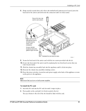
Remove any installed PMC carriers or ADP module so that both slot 1 and slot 2 are not occupied. Installing a PC Card 5. Remove the two front bezel screws and remove the slot 3 filler panel or installed NIC. IP1220 and IP1260 Security Platforms Installation Guide 91 Remove six screws and PMC carrier and ADP module shield HARD DRIVE STATUS ACTIVITY HARD DRIVE STATUS ACTIVITY CONSOLE HDD A POWER HOT SWAP HOT SWAP POWER HOT SWAP HDD B HOT SWAP AUX AUX2 SLOT 3 SLOT 2 IP1260 1000BaseT 1 2 3 4 SLOT 4 RESET Remove PMC carriers or ADP module 00654b.1 6.
Remove any installed PMC carriers or ADP module so that both slot 1 and slot 2 are not occupied. Installing a PC Card 5. Remove the two front bezel screws and remove the slot 3 filler panel or installed NIC. IP1220 and IP1260 Security Platforms Installation Guide 91 Remove six screws and PMC carrier and ADP module shield HARD DRIVE STATUS ACTIVITY HARD DRIVE STATUS ACTIVITY CONSOLE HDD A POWER HOT SWAP HOT SWAP POWER HOT SWAP HDD B HOT SWAP AUX AUX2 SLOT 3 SLOT 2 IP1260 1000BaseT 1 2 3 4 SLOT 4 RESET Remove PMC carriers or ADP module 00654b.1 6.

Installation Guide
Page 92
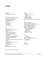
HARD DRIVE STATUS ACTIVITY HARD DRIVE STATUS ACTIVITY CONSOLE HDD A POWER HOT SWAP HOT SWAP POWER HOT SWAP HDD B HOT SWAP AUX AUX2 1000BaseT V2 1000BaseT V2 LINK ACT LINK ACT SLOT 3 SLOT 1 LINK ACT LINK ACT SLOT 2 IP1260 1000BaseT 1 2 3 4 SLOT 4 RESET 00657b.1 92 IP1220 and IP1260 Security Platforms Installation Guide Raise the back end of the PCMCIA carrier card approximately 45 degrees as you insert the front end into slot 3 in the front panel. 7 Installing and Replacing Components Other than Network Interface Cards (NICs) and Accelerated Data Path 7.
HARD DRIVE STATUS ACTIVITY HARD DRIVE STATUS ACTIVITY CONSOLE HDD A POWER HOT SWAP HOT SWAP POWER HOT SWAP HDD B HOT SWAP AUX AUX2 1000BaseT V2 1000BaseT V2 LINK ACT LINK ACT SLOT 3 SLOT 1 LINK ACT LINK ACT SLOT 2 IP1260 1000BaseT 1 2 3 4 SLOT 4 RESET 00657b.1 92 IP1220 and IP1260 Security Platforms Installation Guide Raise the back end of the PCMCIA carrier card approximately 45 degrees as you insert the front end into slot 3 in the front panel. 7 Installing and Replacing Components Other than Network Interface Cards (NICs) and Accelerated Data Path 7.
Installation Guide
Page 93
... the two screws provided with the card. Insert the PC card into place. 12. IP1220 and IP1260 Security Platforms Installation Guide 93 Slide the chassis tray assembly back into the appliance until it clicks into the PC card slot until it snaps in the slot. Press ... SWAP EMI gasket CONSOLE doesn't AUX roll back durinAgUX2 SLOT 1 carrier card installation SLOT 3 LINK ACT IP1260 Arrows indicate LINK ACT SLOT 2 locations where the 1 2 3 4 SLOT 4 gasket might roll back RESET Reinstall the two bezel screws 00644b.1 9. Secure the front end of the appliance, to the left...
... the two screws provided with the card. Insert the PC card into place. 12. IP1220 and IP1260 Security Platforms Installation Guide 93 Slide the chassis tray assembly back into the appliance until it clicks into the PC card slot until it snaps in the slot. Press ... SWAP EMI gasket CONSOLE doesn't AUX roll back durinAgUX2 SLOT 1 carrier card installation SLOT 3 LINK ACT IP1260 Arrows indicate LINK ACT SLOT 2 locations where the 1 2 3 4 SLOT 4 gasket might roll back RESET Reinstall the two bezel screws 00644b.1 9. Secure the front end of the appliance, to the left...

Installation Guide
Page 95
...using the following command, where the number 1 or 2 indicates the PC-card slot: set optional-disk device-id off 3. IP1220 and IP1260 Security Platforms Installation Guide 95 You do not use the following command: halt or reboot You can copy configuration files between the internal ...current/ipso.tgz /cdrom/ 5. Use the cp command to transfer Nokia IPSO images or configuration files to and from the compact flash to the flashmemory PC card, use Nokia Network Voyager to the IP1200 Series appliance by using a console or terminal connection. 3. Caution Hold the flash-memory PC card...
...using the following command, where the number 1 or 2 indicates the PC-card slot: set optional-disk device-id off 3. IP1220 and IP1260 Security Platforms Installation Guide 95 You do not use the following command: halt or reboot You can copy configuration files between the internal ...current/ipso.tgz /cdrom/ 5. Use the cp command to transfer Nokia IPSO images or configuration files to and from the compact flash to the flashmemory PC card, use Nokia Network Voyager to the IP1200 Series appliance by using a console or terminal connection. 3. Caution Hold the flash-memory PC card...

Installation Guide
Page 114
...cord is with the terminal or cable and not with the appliance. Unable to Log In to default settings as inserting a ... to the IP1200 Series. For pinout information, see "To connect to the console" on page 3. 114 IP1220 and IP1260 Security Platforms Installation Guide Problem Not connected with the IP1200 Series. Problem Power supply not... control. Solution Check power source. Solution Contact the Nokia customer support site listed in "Nokia Contact Information" on page 40. Solution Return to the Console Port-No Error Message Two laptop computers (using a...
...cord is with the terminal or cable and not with the appliance. Unable to Log In to default settings as inserting a ... to the IP1200 Series. For pinout information, see "To connect to the console" on page 3. 114 IP1220 and IP1260 Security Platforms Installation Guide Problem Not connected with the IP1200 Series. Problem Power supply not... control. Solution Check power source. Solution Contact the Nokia customer support site listed in "Nokia Contact Information" on page 40. Solution Return to the Console Port-No Error Message Two laptop computers (using a...

Installation Guide
Page 115
...startup procedure is now newpassword. To reset the default database settings 1. IP1220 and IP1260 Security Platforms Installation Guide 115 Finally, return the entire database to reset the password from the command line using Nokia Network Voyager. To reset the admin password to a default value.... With a keyboard and monitor directly connected to the appliance, the boot: prompt does not appear, and you have local serial access to your appliance console to access Network Voyager and the related reference materials, see "Using Nokia Network Voyager" on page 44. When the boot:...
...startup procedure is now newpassword. To reset the default database settings 1. IP1220 and IP1260 Security Platforms Installation Guide 115 Finally, return the entire database to reset the password from the command line using Nokia Network Voyager. To reset the admin password to a default value.... With a keyboard and monitor directly connected to the appliance, the boot: prompt does not appear, and you have local serial access to your appliance console to access Network Voyager and the related reference materials, see "Using Nokia Network Voyager" on page 44. When the boot:...

Installation Guide
Page 116
... information, see the current release notes. Problem Wrong link speed. Solution Correct duplex setting. 116 IP1220 and IP1260 Security Platforms Installation Guide Create the new default configuration. Not Able to Connect to create a new factory...Configuration Database Management (Config > System Configuration > Manage Configuration Sets), choose the option to Nokia Network Voyager Using the Ethernet Port, But Console Access Works Problem Using the wrong Ethernet cable. Do Not Get a Login Prompt-Error...on a port is configured as listed in "Nokia Contact Information" on the appliance.
... information, see the current release notes. Problem Wrong link speed. Solution Correct duplex setting. 116 IP1220 and IP1260 Security Platforms Installation Guide Create the new default configuration. Not Able to Connect to create a new factory...Configuration Database Management (Config > System Configuration > Manage Configuration Sets), choose the option to Nokia Network Voyager Using the Ethernet Port, But Console Access Works Problem Using the wrong Ethernet cable. Do Not Get a Login Prompt-Error...on a port is configured as listed in "Nokia Contact Information" on the appliance.
Installation Guide
Page 125
...services modules accessing and removing DIMMs 100 activating interfaces 56 ADP services modules 67 appliance configuring 39 management 19 overview 19 rack-mounting 35 C caution notices 14 Check Point VPN-1 requirements 30 component locations 19 configuring using a console connection 40 connecting Ethernet devices 44 connecting network interfaces 44 connections Ethernet network ... 44 fiber-optic Gigabit Ethernet NICs 21, 65 flash memory 88 front panel 17, 19 G gasket 50 grounding 34 D data communications equipment device 40 IP1220 and IP1260 Security Platforms Installation Guide Index - 125
...services modules accessing and removing DIMMs 100 activating interfaces 56 ADP services modules 67 appliance configuring 39 management 19 overview 19 rack-mounting 35 C caution notices 14 Check Point VPN-1 requirements 30 component locations 19 configuring using a console connection 40 connecting Ethernet devices 44 connecting network interfaces 44 connections Ethernet network ... 44 fiber-optic Gigabit Ethernet NICs 21, 65 flash memory 88 front panel 17, 19 G gasket 50 grounding 34 D data communications equipment device 40 IP1220 and IP1260 Security Platforms Installation Guide Index - 125