GSM7212 Hardware manual
Page 10
... (1,000 Mbps only) • Green: Power is supplied, and the switch is operating normally. • Yellow: Power supply present, but it has failed. • Off: Power is disconnected. Power receptacle Figure 2-2 2-2 v1.0, March 2006 Introduction LED Descriptions for the supplied power cord. FDX • Green: Full-duplex...receiving packets in 10 Mbps. ACT (activity) • Blinking green: The port is detected. Managed Layer 2 Switches GSM7212, GSM7224, and GSM7248 Hardware Installation Guide The following table describes the LEDs on the port.. • Solid green: Link is up ...
... (1,000 Mbps only) • Green: Power is supplied, and the switch is operating normally. • Yellow: Power supply present, but it has failed. • Off: Power is disconnected. Power receptacle Figure 2-2 2-2 v1.0, March 2006 Introduction LED Descriptions for the supplied power cord. FDX • Green: Full-duplex...receiving packets in 10 Mbps. ACT (activity) • Blinking green: The port is detected. Managed Layer 2 Switches GSM7212, GSM7224, and GSM7248 Hardware Installation Guide The following table describes the LEDs on the port.. • Solid green: Link is up ...
GSM7212 Hardware manual
Page 11
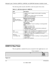
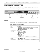
....0, March 2006 Table 2-2. Managed Layer 2 Switches GSM7212, GSM7224, and GSM7248 Hardware Installation Guide GSM7224 Front Panel and LEDs The following table shows the GSM7224 LEDs on the front of the GSM7224. GSM7224 LED Description LED Description Power • Green: Power is supplied, and the switch is operating normally. • Yellow: Power supply present, but it has failed. •...
....0, March 2006 Table 2-2. Managed Layer 2 Switches GSM7212, GSM7224, and GSM7248 Hardware Installation Guide GSM7224 Front Panel and LEDs The following table shows the GSM7224 LEDs on the front of the GSM7224. GSM7224 LED Description LED Description Power • Green: Power is supplied, and the switch is operating normally. • Yellow: Power supply present, but it has failed. •...
GSM7212 Hardware manual
Page 12
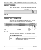
... front panel contains LEDs, RJ-45 jacks, SFP module bays, and a console port. GSM7248 LED Description LED Power Description • Green: Power is supplied, and the switch is operating normally. • Off: No power is applied, or power failure. 2-4 Introduction v1.0, March 2006 LEDs Figure 2-5 RJ-45 jacks SFP module bays Console port The following figure shows...
... front panel contains LEDs, RJ-45 jacks, SFP module bays, and a console port. GSM7248 LED Description LED Power Description • Green: Power is supplied, and the switch is operating normally. • Off: No power is applied, or power failure. 2-4 Introduction v1.0, March 2006 LEDs Figure 2-5 RJ-45 jacks SFP module bays Console port The following figure shows...

GSM7212 Hardware manual
Page 13
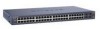
GSM7248 Rear Panel The rear panel has a standard AC power receptacle for the supplied power cord. Link or Activity (right) • Green: Link is up. • Blinking...your system from potential damage. Only a trained service technician should service components inside these compartments. Introduction 2-5 v1.0, March 2006 GSM7248 LED Description (continued) 10/100/1000 ports (two LEDs) SFP port (1,000 Mbps only) Speed (left) • ... Off: No link is sending or receiving packets in 10 Mbps. Managed Layer 2 Switches GSM7212, GSM7224, and GSM7248 Hardware Installation Guide Table 2-3.
GSM7248 Rear Panel The rear panel has a standard AC power receptacle for the supplied power cord. Link or Activity (right) • Green: Link is up. • Blinking...your system from potential damage. Only a trained service technician should service components inside these compartments. Introduction 2-5 v1.0, March 2006 GSM7248 LED Description (continued) 10/100/1000 ports (two LEDs) SFP port (1,000 Mbps only) Speed (left) • ... Off: No link is sending or receiving packets in 10 Mbps. Managed Layer 2 Switches GSM7212, GSM7224, and GSM7248 Hardware Installation Guide Table 2-3.

GSM7212 Hardware manual
Page 14
... the voltage selection switch (if provided) on the power supply is damaged. - Doing so can cause fire or electric shock by shorting out interior components. • Use the product only with approved equipment. • Allow the product to operate with the power available in a wet environment. Managed Layer 2 Switches GSM7212, GSM7224, and GSM7248 Hardware Installation Guide...
... the voltage selection switch (if provided) on the power supply is damaged. - Doing so can cause fire or electric shock by shorting out interior components. • Use the product only with approved equipment. • Allow the product to operate with the power available in a wet environment. Managed Layer 2 Switches GSM7212, GSM7224, and GSM7248 Hardware Installation Guide...
GSM7212 Hardware manual
Page 15
...increases and decreases in your country. Avoid sudden stops and uneven surfaces. Managed Layer 2 Switches GSM7212, GSM7224, and GSM7248 Hardware Installation Guide • Use only approved power cables. If you must be stepped on the product's electrical ratings label. If you ...your system from a cable. Introduction 2-7 v1.0, March 2006 The power cable must use an extension cable, use a surge suppressor, line conditioner, or uninterruptible power supply (UPS). • Position system cables and power cables carefully; route cables so that nothing rests on the product....
...increases and decreases in your country. Avoid sudden stops and uneven surfaces. Managed Layer 2 Switches GSM7212, GSM7224, and GSM7248 Hardware Installation Guide • Use only approved power cables. If you must be stepped on the product's electrical ratings label. If you ...your system from a cable. Introduction 2-7 v1.0, March 2006 The power cable must use an extension cable, use a surge suppressor, line conditioner, or uninterruptible power supply (UPS). • Position system cables and power cables carefully; route cables so that nothing rests on the product....
GSM7212 Hardware manual
Page 19
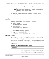
... a Location. Install the Switch. See "Install the Switch" on page 3-3. 2. Managed Layer 2 Switches GSM7212, GSM7224, and GSM7248 Hardware Installation Guide 4. See "Package Contents" on page 3-6. Inspect the products and accessories for replacement. 5. See "Connect to Power and Check the LEDs" on page 3-1. You need the rack-mount kit supplied with your local NETGEAR reseller for damage. See...
... a Location. Install the Switch. See "Install the Switch" on page 3-3. 2. Managed Layer 2 Switches GSM7212, GSM7224, and GSM7248 Hardware Installation Guide 4. See "Package Contents" on page 3-6. Inspect the products and accessories for replacement. 5. See "Connect to Power and Check the LEDs" on page 3-1. You need the rack-mount kit supplied with your local NETGEAR reseller for damage. See...


