
GS748TR Hardware manual
Page 2
...(s) described herein. The Federal Office for example, test transmitters) in accordance with the conditions set out in the operating instructions. Trademarks NETGEAR, the NETGEAR logo, and Auto Uplink are registered trademarks or trademarks of Microsoft Corporation. Microsoft, Windows, and Windows NT are copyright Intoto, Inc. NETGEAR does not assume any liability that the GS700TR Series Smart Switch has been suppressed in this equipment...
...(s) described herein. The Federal Office for example, test transmitters) in accordance with the conditions set out in the operating instructions. Trademarks NETGEAR, the NETGEAR logo, and Auto Uplink are registered trademarks or trademarks of Microsoft Corporation. Microsoft, Windows, and Windows NT are copyright Intoto, Inc. NETGEAR does not assume any liability that the GS700TR Series Smart Switch has been suppressed in this equipment...

GS748TR Hardware manual
Page 5
... a procedure that will save time or resources. Tip: This format is used to the equipment. This manual uses the following formats to highlight special messages: Note: This format is used to install, configure and troubleshoot the GS700TR Series Smart Switch. Warning: Ignoring this type of note may result in the following paragraphs: • Typographical Conventions. About This Manual The NETGEAR® GS700TR Series Hardware Installation Guide describes how to...
... a procedure that will save time or resources. Tip: This format is used to the equipment. This manual uses the following formats to highlight special messages: Note: This format is used to install, configure and troubleshoot the GS700TR Series Smart Switch. Warning: Ignoring this type of note may result in the following paragraphs: • Typographical Conventions. About This Manual The NETGEAR® GS700TR Series Hardware Installation Guide describes how to...

GS748TR Hardware manual
Page 6
... warning. Use the Print button on the browser toolbar to access the full NETGEAR, Inc. vi About This Manual v1.0, December 2007 GS700TR Series Hardware Installation Guide Danger: This is written for the GS700TR Series Smart Switch according to these specifications: Product Version Manual Publication Date GS700TR Series Smart Switch December 2007 Note: Product updates are available on the NETGEAR, Inc. online knowledge base for the product model. • Links to PDF versions of...
... warning. Use the Print button on the browser toolbar to access the full NETGEAR, Inc. vi About This Manual v1.0, December 2007 GS700TR Series Hardware Installation Guide Danger: This is written for the GS700TR Series Smart Switch according to these specifications: Product Version Manual Publication Date GS700TR Series Smart Switch December 2007 Note: Product updates are available on the NETGEAR, Inc. online knowledge base for the product model. • Links to PDF versions of...
GS748TR Hardware manual
Page 9
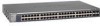
... which support 1000 (1000Base-SX/LX)/100M SFP. • GS748TR - With a Web-based Graphical User Interface (GUI), the switch's many capabilities can be viewed and used in a simple and intuitive manner. Using Gigabit ports, high-speed connections can be made to the GS700TR Series Smart Switch and provides the following information: • Overview • Features • Package Contents Overview This Installation Guide is shipped ready for the following NETGEAR Smart Switches: •...
... which support 1000 (1000Base-SX/LX)/100M SFP. • GS748TR - With a Web-based Graphical User Interface (GUI), the switch's many capabilities can be viewed and used in a simple and intuitive manner. Using Gigabit ports, high-speed connections can be made to the GS700TR Series Smart Switch and provides the following information: • Overview • Features • Package Contents Overview This Installation Guide is shipped ready for the following NETGEAR Smart Switches: •...

GS748TR Hardware manual
Page 10
... fiber connections using SFP GBIC modules. All ports can be free-standing, or rack mounted in half- The maximum segment length is IEEE-compliant and offers low latency for traffic prioritization. Initial discovery of Service (CoS) for high-speed networking. If both are plugged in, the fiber connection is active, with two physical connections, SFP fiber and RJ-45 copper. These features provide better understanding and control of the NETGEAR Smart Switch...
... fiber connections using SFP GBIC modules. All ports can be free-standing, or rack mounted in half- The maximum segment length is IEEE-compliant and offers low latency for traffic prioritization. Initial discovery of Service (CoS) for high-speed networking. If both are plugged in, the fiber connection is active, with two physical connections, SFP fiber and RJ-45 copper. These features provide better understanding and control of the NETGEAR Smart Switch...

GS748TR Hardware manual
Page 11
... Series Smart Switch. and Half-duplex functions for all ports to make the right connection. • Automatic address learning function to build the packet-forwarding information table. GS700TR Series Hardware Installation Guide • Auto Uplink™ on all 10/100/1000 Mbps ports. • Store-and-Forward transmission to remove bad packets from the network. • Full-duplex IEEE 802.3x pause frame flow control. • Active flow control to minimize packet loss/frame drops. • Half-duplex back-pressure control...
... Series Smart Switch. and Half-duplex functions for all ports to make the right connection. • Automatic address learning function to build the packet-forwarding information table. GS700TR Series Hardware Installation Guide • Auto Uplink™ on all 10/100/1000 Mbps ports. • Store-and-Forward transmission to remove bad packets from the network. • Full-duplex IEEE 802.3x pause frame flow control. • Active flow control to minimize packet loss/frame drops. • Half-duplex back-pressure control...

GS748TR Hardware manual
Page 13
...; 24 RJ-45 connectors for 10/100/1000Mbps auto sensing Gigabit Ethernet switching ports. • Two SFP slots for SFP modules supporting 1000(1000Base-SX/LX)/100M SFP. • Reset button to restart the device. • Recessed default reset button to restore the device back to the factory defaults. • Port LEDS 2-5 v1.0, December 2007 Chapter 2 Physical Description This chapter describes the NETGEAR Smart Switch hardware features. Topics include: • GS724TR Front and Back...
...; 24 RJ-45 connectors for 10/100/1000Mbps auto sensing Gigabit Ethernet switching ports. • Two SFP slots for SFP modules supporting 1000(1000Base-SX/LX)/100M SFP. • Reset button to restart the device. • Recessed default reset button to restore the device back to the factory defaults. • Port LEDS 2-5 v1.0, December 2007 Chapter 2 Physical Description This chapter describes the NETGEAR Smart Switch hardware features. Topics include: • GS724TR Front and Back...

GS748TR Hardware manual
Page 14
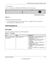
... default reset button to restore the device back to the factory defaults. • Port LEDs 2-6 Physical Description v1.0, December 2007 GS700TR Series Hardware Installation Guide • System LEDs Figure 2-2 illustrates the NETGEAR GS724TR Smart Switch back panel: Figure 2-2 RS-232 Power Connector The back panel contains the following: • A 100-240VAC/50-60 Hz universal input, which is capable of sensing the line speed and negotiating the operation duplex mode with...
... default reset button to restore the device back to the factory defaults. • Port LEDs 2-6 Physical Description v1.0, December 2007 GS700TR Series Hardware Installation Guide • System LEDs Figure 2-2 illustrates the NETGEAR GS724TR Smart Switch back panel: Figure 2-2 RS-232 Power Connector The back panel contains the following: • A 100-240VAC/50-60 Hz universal input, which is capable of sensing the line speed and negotiating the operation duplex mode with...
GS748TR Hardware manual
Page 15
... Series Hardware Installation Guide • System LEDs Figure 2-4 illustrates the NETGEAR GS748TR Smart Switch back panel: RS-232 Power Connector Figure 2-4 The back panel contains the following table describes the port LED designations. Packet transmission or reception is a standard AC power receptacle for accommodating the supplied power cord. A valid 1000Mbps link is established on the port at 1000Mbps. • Solid Yellow - Table 2-1. No 10/100Mbps link is established on the port. • Flashing...
... Series Hardware Installation Guide • System LEDs Figure 2-4 illustrates the NETGEAR GS748TR Smart Switch back panel: RS-232 Power Connector Figure 2-4 The back panel contains the following table describes the port LED designations. Packet transmission or reception is a standard AC power receptacle for accommodating the supplied power cord. A valid 1000Mbps link is established on the port at 1000Mbps. • Solid Yellow - Table 2-1. No 10/100Mbps link is established on the port. • Flashing...
GS748TR Hardware manual
Page 16
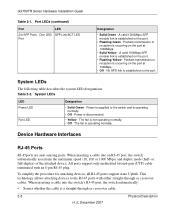
One LED/ SFP Link/ACT LED Port Designation • Solid Green - Packets transmission or reception is occurring on the port. • Flashing Yellow - System LEDs LED Power LED Fan LED Designation • Solid Green - The fan is disconnected. • Yellow - Device Hardware Interfaces RJ-45 Ports RJ-45ports are auto-sensing ports. To simplify the procedure for attaching devices, all RJ-45 ports support Auto Uplink. A valid 100Mbps SFP module link is supplied to the RJ-45 ports with an 8-pin RJ...
One LED/ SFP Link/ACT LED Port Designation • Solid Green - Packets transmission or reception is occurring on the port. • Flashing Yellow - System LEDs LED Power LED Fan LED Designation • Solid Green - The fan is disconnected. • Yellow - Device Hardware Interfaces RJ-45 Ports RJ-45ports are auto-sensing ports. To simplify the procedure for attaching devices, all RJ-45 ports support Auto Uplink. A valid 100Mbps SFP module link is supplied to the RJ-45 ports with an 8-pin RJ...

GS748TR Hardware manual
Page 17
... fiber connections on the network. The module bay is a combo port, sharing a connection with the attached device, without requiring user intervention. When you can be removed. SFP GBIC Module The GBIC module bays accommodate standard SFP GBIC modules, such as when connecting the port to a router, switch, or hub). • Configures the RJ-45 port to enable communications with an RJ-45 port. Factory Defaults Button The Smart Switch has a Factory Default button so that you enable the Factory Default button, all settings, including the password, VLAN settings...
... fiber connections on the network. The module bay is a combo port, sharing a connection with the attached device, without requiring user intervention. When you can be removed. SFP GBIC Module The GBIC module bays accommodate standard SFP GBIC modules, such as when connecting the port to a router, switch, or hub). • Configures the RJ-45 port to enable communications with an RJ-45 port. Factory Defaults Button The Smart Switch has a Factory Default button so that you enable the Factory Default button, all settings, including the password, VLAN settings...
GS748TR Hardware manual
Page 19
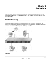
Figure 3-1 v1.0, December 2007 3-11 With full-duplex enabled, the switch port connected to provide flexibility in configuring your network connections. Chapter 3 Applications Your NETGEAR Smart Switch is designed to the server or PC can provide 2000 Mbps throughput. Desktop Switching The NETGEAR Smart Switch can be used as a desktop switch to build a small network that enables users to have 1000 Mbps access to a file server. It can be used as a stand-alone device or with 10 Mbps, 100 Mbps, and 1000 Mbps hubs and switches.
Figure 3-1 v1.0, December 2007 3-11 With full-duplex enabled, the switch port connected to provide flexibility in configuring your network connections. Chapter 3 Applications Your NETGEAR Smart Switch is designed to the server or PC can provide 2000 Mbps throughput. Desktop Switching The NETGEAR Smart Switch can be used as a desktop switch to build a small network that enables users to have 1000 Mbps access to a file server. It can be used as a stand-alone device or with 10 Mbps, 100 Mbps, and 1000 Mbps hubs and switches.
GS748TR Hardware manual
Page 21
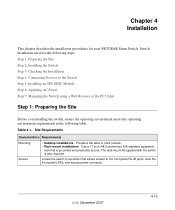
.... Table 4-1. Provide a flat table or shelf surface. • Rack-mount installations - Chapter 4 Installation This chapter describes the installation procedures for your NETGEAR Smart Switch. Locate the switch in the following steps: Step 1: Preparing the Site Step 2: Installing the Switch Step 3: Checking the Installation Step 4: Connecting Devices to the front panel RJ-45 ports, view the front panel LEDs, and access power connector. v1.0, December 2007 4-13 The rack-mount kit supplied with the switch is...
.... Table 4-1. Provide a flat table or shelf surface. • Rack-mount installations - Chapter 4 Installation This chapter describes the installation procedures for your NETGEAR Smart Switch. Locate the switch in the following steps: Step 1: Preparing the Site Step 2: Installing the Switch Step 3: Checking the Installation Step 4: Connecting Devices to the front panel RJ-45 ports, view the front panel LEDs, and access power connector. v1.0, December 2007 4-13 The rack-mount kit supplied with the switch is...
GS748TR Hardware manual
Page 24
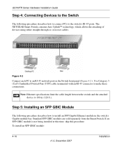
... switch's RJ-45 ports. Standard SFP GBIC modules are sold separately from the Smart Switch. If an SFP GBIC module is not being installed at this time, skip this procedure. GS700TR Series Hardware Installation Guide Step 4: Connecting Devices to the Switch The following procedure describes how to install an SFP Gigabit Ethernet module in the switch's Gigabit module bay. Figure 4-2 Connect each PC to an RJ-45 network port on the Switch front panel (Figure 4-2 ). To install an SFP GBIC module...
... switch's RJ-45 ports. Standard SFP GBIC modules are sold separately from the Smart Switch. If an SFP GBIC module is not being installed at this time, skip this procedure. GS700TR Series Hardware Installation Guide Step 4: Connecting Devices to the Switch The following procedure describes how to install an SFP Gigabit Ethernet module in the switch's Gigabit module bay. Figure 4-2 Connect each PC to an RJ-45 network port on the Switch front panel (Figure 4-2 ). To install an SFP GBIC module...

GS748TR Hardware manual
Page 25
... can turn off power to the switch. GS700TR Series Hardware Installation Guide Insert the SFP module into the connector. Connect the 3-pronged end of the switch. 2. Installation v1.0, December 2007 4-17 Before connecting the power cord, select an AC outlet that the power source is not controlled by connecting or disconnecting the power cord. After selecting an appropriate outlet, use the following procedure to Appendix A . Figure 4-3 Step 6: Applying AC Power NETGEAR Smart Switch...
... can turn off power to the switch. GS700TR Series Hardware Installation Guide Insert the SFP module into the connector. Connect the 3-pronged end of the switch. 2. Installation v1.0, December 2007 4-17 Before connecting the power cord, select an AC outlet that the power source is not controlled by connecting or disconnecting the power cord. After selecting an appropriate outlet, use the following procedure to Appendix A . Figure 4-3 Step 6: Applying AC Power NETGEAR Smart Switch...

GS748TR Hardware manual
Page 26
... Series Hardware Installation Guide Step 7: Managing the Switch using a Web Browser or the PC Utility The NETGEAR Smart Switch contains software for the first time, the Smart Switch can be configured using the management software. However, the management software enables the setup of VLAN and Trunking features, and also improves the efficiency of the switch, which results in the improvement of its overall performance as well as the performance of the network. After powering up , there is a default IP address...
... Series Hardware Installation Guide Step 7: Managing the Switch using a Web Browser or the PC Utility The NETGEAR Smart Switch contains software for the first time, the Smart Switch can be configured using the management software. However, the management software enables the setup of VLAN and Trunking features, and also improves the efficiency of the switch, which results in the improvement of its overall performance as well as the performance of the network. After powering up , there is a default IP address...

GS748TR Hardware manual
Page 27
... Troubleshooting Chart The following table lists symptoms, causes, and solutions of possible problems. Table A-1. Ensure all cables used are correct and comply with Ethernet specifications. Check the crimp on the switch and the connected device are functioning. Appendix A Troubleshooting This chapter provides information about troubleshooting the NETGEAR Smart Switch. or full-duplex setting on the connectors and make sure that the plug is properly inserted and locked into the port...
... Troubleshooting Chart The following table lists symptoms, causes, and solutions of possible problems. Table A-1. Ensure all cables used are correct and comply with Ethernet specifications. Check the crimp on the switch and the connected device are functioning. Appendix A Troubleshooting This chapter provides information about troubleshooting the NETGEAR Smart Switch. or full-duplex setting on the connectors and make sure that the plug is properly inserted and locked into the port...

GS748TR Hardware manual
Page 28
... switch and then reapply AC power. If you are not properly connected, or cabling does not meet Ethernet guidelines. If the problem continues, contact NETGEAR technical support. Troubleshooting Chart Symptom Cause Solution A segment or device is only one step at a time. ACT LED is flashing continuously on all connectors are in the required ports. A-20 v1.0, December 2007 Troubleshooting Ensure that the cabling is disabled. GS700TR Series Hardware Installation Guide Table A-1. A network...
... switch and then reapply AC power. If you are not properly connected, or cabling does not meet Ethernet guidelines. If the problem continues, contact NETGEAR technical support. Troubleshooting Chart Symptom Cause Solution A segment or device is only one step at a time. ACT LED is flashing continuously on all connectors are in the required ports. A-20 v1.0, December 2007 Troubleshooting Ensure that the cabling is disabled. GS700TR Series Hardware Installation Guide Table A-1. A network...

GS748TR Hardware manual
Page 35
...AGM733 2-9 Applying AC Power 4-17 Attaching Switch to a Rack 4-15 Auto Sensing 1-2 Auto Uplink 2-8, 2-9 Auto-negotiating 1-2 Auto-sensing 2-8 B Back-pressure 1-3 Brackets 4-14 C Category 5 Unshielded Twisted-Pair 1-2 Checking the Installation 4-15 Class of Service 1-2 Combo Port 2-9 Combo Ports 1-2 Connecting Devices to the Switch 4-16 Copper 1-1 Crossover 2-8 D Default IP Address 4-18 Default Reset Button 2-5, 2-6 Device Hardware Interfaces 2-8 Duplex Mode 2-8 E Example of Desktop Switching 3-11 F Factory Default Button 2-9 Factory Defaults 2-5 Fan LED 2-8 Fiber Connectivity 1-1 Flat Surface...
...AGM733 2-9 Applying AC Power 4-17 Attaching Switch to a Rack 4-15 Auto Sensing 1-2 Auto Uplink 2-8, 2-9 Auto-negotiating 1-2 Auto-sensing 2-8 B Back-pressure 1-3 Brackets 4-14 C Category 5 Unshielded Twisted-Pair 1-2 Checking the Installation 4-15 Class of Service 1-2 Combo Port 2-9 Combo Ports 1-2 Connecting Devices to the Switch 4-16 Copper 1-1 Crossover 2-8 D Default IP Address 4-18 Default Reset Button 2-5, 2-6 Device Hardware Interfaces 2-8 Duplex Mode 2-8 E Example of Desktop Switching 3-11 F Factory Default Button 2-9 Factory Defaults 2-5 Fan LED 2-8 Fiber Connectivity 1-1 Flat Surface...

GS748TR Hardware manual
Page 36
... 1-3 Pause Frame Flow Control 1-3 Phillips Screwdriver 4-14 Port LEDs 2-7 Power cord 1-4 Preparing the Site 4-13 R Rack 4-14 Rack-mount Kit 1-4, 4-14 Reset Button 2-5, 2-6 RJ-45 1-2 RJ-45 Ports 2-8 Rubber Footpad 4-14 Rubber footpads 1-4 S SFP GBIC Module 2-9 SFP Link/ACT LED 2-8 SFP Module Bay 4-17 Site Requirements 4-13 Small Form-factor Pluggable (SFP) 1-2 Smart Switch Resource CD 1-4 Smart Wizard Discovery 1-2 Straight-through 2-8 Support Information Card 1-4 System LEDs 2-8 T Temperature 4-14 Traffic Control 1-1 Troubleshooting Chart A-19 U User Intervention 2-9 User's Manual 1-4 UTP...
... 1-3 Pause Frame Flow Control 1-3 Phillips Screwdriver 4-14 Port LEDs 2-7 Power cord 1-4 Preparing the Site 4-13 R Rack 4-14 Rack-mount Kit 1-4, 4-14 Reset Button 2-5, 2-6 RJ-45 1-2 RJ-45 Ports 2-8 Rubber Footpad 4-14 Rubber footpads 1-4 S SFP GBIC Module 2-9 SFP Link/ACT LED 2-8 SFP Module Bay 4-17 Site Requirements 4-13 Small Form-factor Pluggable (SFP) 1-2 Smart Switch Resource CD 1-4 Smart Wizard Discovery 1-2 Straight-through 2-8 Support Information Card 1-4 System LEDs 2-8 T Temperature 4-14 Traffic Control 1-1 Troubleshooting Chart A-19 U User Intervention 2-9 User's Manual 1-4 UTP...


