GS7xxTS-TPS Hardware Installation Guide
Page 3
Table of Contents Chapter 1 Introduction Overview 7 Features 7 Stacking 9 Package Contents 10 Chapter 2 Physical Description GS728TS Front-Panel and Back-Panel Configuration 12 GS728TPS Front-Panel and Back-Panel Configuration 13 GS752TS Front-Panel and Back-Panel Configuration 15... Designations 17 RJ-45 Port LEDs 17 SFP Port LEDs 18 System LEDs 18 Device Hardware Interfaces 19 RJ-45 Ports 19 SFP Ports 19 Reset Button 20 Factory Defaults Button 20 Select Button 20 Chapter 3 Applications Desktop Switching 22 Backbone Switching 23 Chapter 4 Installation Step 1: Preparing the ...
Table of Contents Chapter 1 Introduction Overview 7 Features 7 Stacking 9 Package Contents 10 Chapter 2 Physical Description GS728TS Front-Panel and Back-Panel Configuration 12 GS728TPS Front-Panel and Back-Panel Configuration 13 GS752TS Front-Panel and Back-Panel Configuration 15... Designations 17 RJ-45 Port LEDs 17 SFP Port LEDs 18 System LEDs 18 Device Hardware Interfaces 19 RJ-45 Ports 19 SFP Ports 19 Reset Button 20 Factory Defaults Button 20 Select Button 20 Chapter 3 Applications Desktop Switching 22 Backbone Switching 23 Chapter 4 Installation Step 1: Preparing the ...
GS7xxTS-TPS Hardware Installation Guide
Page 12
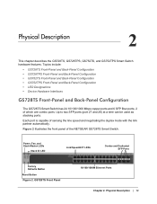
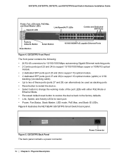
..., and Stack Master LEDs Stack ID LED Link/Speed/ACT LEDs Combo and Dedicated SFP Ports Factory Defaults Button Reset Button Figure 2. Each port is capable of the NETGEAR GS728TS Smart Switch. Topics include: • GS728TS Front-Panel and Back-Panel Configuration • GS728TPS Front-Panel and Back-Panel Configuration • GS752TS Front-Panel...
..., and Stack Master LEDs Stack ID LED Link/Speed/ACT LEDs Combo and Dedicated SFP Ports Factory Defaults Button Reset Button Figure 2. Each port is capable of the NETGEAR GS728TS Smart Switch. Topics include: • GS728TS Front-Panel and Back-Panel Configuration • GS728TPS Front-Panel and Back-Panel Configuration • GS752TS Front-Panel...
GS7xxTS-TPS Hardware Installation Guide
Page 13
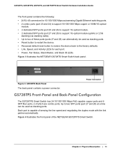
...; Up to two of these ports (ports 27 and 28) can alternatively be used as stacking ports • Reset button to restart the device. • Recessed default reset button to restore the device back to two SFP ports (port 27 and 28) at a time can be used...Mbps PoE capable copper ports and 6 SFP fiber ports, 2 of the NETGEAR GS728TPS Smart Switch. Figure 3. Figure 4 illustrates the front panel of which are combo ports. Chapter 2. Figure 3 illustrates the NETGEAR GS728TS Smart Switch back panel. GS728TS Back Panel The back panel contains a power connector. Each port is capable...
...; Up to two of these ports (ports 27 and 28) can alternatively be used as stacking ports • Reset button to restart the device. • Recessed default reset button to restore the device back to two SFP ports (port 27 and 28) at a time can be used...Mbps PoE capable copper ports and 6 SFP fiber ports, 2 of the NETGEAR GS728TPS Smart Switch. Figure 3. Figure 4 illustrates the front panel of which are combo ports. Chapter 2. Figure 3 illustrates the NETGEAR GS728TS Smart Switch back panel. GS728TS Back Panel The back panel contains a power connector. Each port is capable...
GS7xxTS-TPS Hardware Installation Guide
Page 14
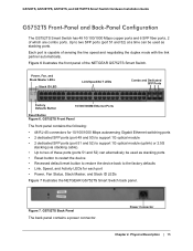
GS728TS, GS728TPS, GS752TS, and GS752TPS Smart Switch Hardware Installation Guide Power, Fan, LED mode, PoE Max, and Stack Master LEDs Stack ID LED Link/Speed/ACT LEDs Combo and Dedicated SFP Ports Factory Defaults Button Reset Button Select Button 10/100/1000M PoE capable Ethernet Ports Figure 4.... each port. • Power, Fan Status, Stack Master, LED mode, PoE Max, and Stack ID LEDs. Figure 5. Figure 5 illustrates the NETGEAR GS728TPS Smart Switch back panel. Physical Description Power Connector GS728TPS Back Panel The back panel contains a power connector. 14 | Chapter 2.
GS728TS, GS728TPS, GS752TS, and GS752TPS Smart Switch Hardware Installation Guide Power, Fan, LED mode, PoE Max, and Stack Master LEDs Stack ID LED Link/Speed/ACT LEDs Combo and Dedicated SFP Ports Factory Defaults Button Reset Button Select Button 10/100/1000M PoE capable Ethernet Ports Figure 4.... each port. • Power, Fan Status, Stack Master, LED mode, PoE Max, and Stack ID LEDs. Figure 5. Figure 5 illustrates the NETGEAR GS728TPS Smart Switch back panel. Physical Description Power Connector GS728TPS Back Panel The back panel contains a power connector. 14 | Chapter 2.
GS7xxTS-TPS Hardware Installation Guide
Page 15
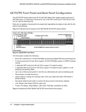
... Ethernet Ports Reset Button Figure 6. Power Connector Chapter 2. GS752TS Front Panel The front panel contains the following: • 48 RJ-45 connectors for each port • Power, Fan Status, Stack Master, and Stack ID LEDs Figure 7 illustrates the NETGEAR GS752TS Smart ...Switch back panel. Physical Description | 15 Up to two SFP ports (port 51 and 52) at a time can alternatively be used as stacking ports. Figure 6 illustrates the front panel of sensing the line speed and negotiating the duplex mode with the link partner automatically. GS728TS...
... Ethernet Ports Reset Button Figure 6. Power Connector Chapter 2. GS752TS Front Panel The front panel contains the following: • 48 RJ-45 connectors for each port • Power, Fan Status, Stack Master, and Stack ID LEDs Figure 7 illustrates the NETGEAR GS752TS Smart ...Switch back panel. Physical Description | 15 Up to two SFP ports (port 51 and 52) at a time can alternatively be used as stacking ports. Figure 6 illustrates the front panel of sensing the line speed and negotiating the duplex mode with the link partner automatically. GS728TS...
GS7xxTS-TPS Hardware Installation Guide
Page 16
Physical Description GS728TS, GS728TPS, GS752TS, and GS752TPS Smart Switch Hardware Installation Guide GS752TPS Front-Panel and Back-Panel Configuration The GS752TPS Smart Switch has 48 10/100/1000 Mbps PoE capable copper ports and 6 SFP fiber ports, 2 of the NETGEAR GS752TPS Smart Switch. ...Button Link/Speed/ACT LEDs Combo and Dedicated SFP Ports Factory Defaults Button 10/100/1000M PoE capable Ethernet Ports Reset Button Figure 8. Figure 9 illustrates the NETGEAR GS752TPS Smart Switch back panel. 16 | Chapter 2. GS752TPS Front Panel The front panel contains the following: ...
Physical Description GS728TS, GS728TPS, GS752TS, and GS752TPS Smart Switch Hardware Installation Guide GS752TPS Front-Panel and Back-Panel Configuration The GS752TPS Smart Switch has 48 10/100/1000 Mbps PoE capable copper ports and 6 SFP fiber ports, 2 of the NETGEAR GS752TPS Smart Switch. ...Button Link/Speed/ACT LEDs Combo and Dedicated SFP Ports Factory Defaults Button 10/100/1000M PoE capable Ethernet Ports Reset Button Figure 8. Figure 9 illustrates the NETGEAR GS752TPS Smart Switch back panel. 16 | Chapter 2. GS752TPS Front Panel The front panel contains the following: ...

GS7xxTS-TPS Hardware Installation Guide
Page 20
...a Factory Defaults button on . You need to press the button for over two seconds. This action is loaded into the switch as it resets. When you can change the LED mode. 20 | Chapter 2. The front-panel LEDs should extinguish and light again as a paper clip into...1 second to its Power On Self Test (POST). To operate the Factory Defaults button, insert a device such as a stacking cable. Physical Description GS728TS, GS728TPS, GS752TS, and GS752TPS Smart Switch Hardware Installation Guide Note: Direct attach cable AGC761 (2.5G) is sold separately. The AGC761 cable is recommended ...
...a Factory Defaults button on . You need to press the button for over two seconds. This action is loaded into the switch as it resets. When you can change the LED mode. 20 | Chapter 2. The front-panel LEDs should extinguish and light again as a paper clip into...1 second to its Power On Self Test (POST). To operate the Factory Defaults button, insert a device such as a stacking cable. Physical Description GS728TS, GS728TPS, GS752TS, and GS752TPS Smart Switch Hardware Installation Guide Note: Direct attach cable AGC761 (2.5G) is sold separately. The AGC761 cable is recommended ...
GS7xxTS-TPS Hardware Installation Guide
Page 22
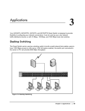
With full-duplex enabled, the switch port connected to the server or PC can be used as your network connections. Desktop Switching Chapter 3. Applications 3 Your GS728TS, GS728TPS, GS752TS, and GS752TPS Smart Switch is designed to a file server. It can be used as a desktop switch to build a small network that ... 31 32 33 34 35 36 37 38 39 40 41 42 43 44 45 46 47 48 49F 50F GS752TXS 51F 52F SFP + Reset Factory Defaults Green=10G Link Yellow=1G Blink=ACT ` ` ` ` Figure 10. Applications | 22 Desktop Switching The Smart Switch can provide 2000 Mbps...
With full-duplex enabled, the switch port connected to the server or PC can be used as your network connections. Desktop Switching Chapter 3. Applications 3 Your GS728TS, GS728TPS, GS752TS, and GS752TPS Smart Switch is designed to a file server. It can be used as a desktop switch to build a small network that ... 31 32 33 34 35 36 37 38 39 40 41 42 43 44 45 46 47 48 49F 50F GS752TXS 51F 52F SFP + Reset Factory Defaults Green=10G Link Yellow=1G Blink=ACT ` ` ` ` Figure 10. Applications | 22 Desktop Switching The Smart Switch can provide 2000 Mbps...

GS7xxTS-TPS Hardware Installation Guide
Page 23
...46 47 48 49F 50F GS752TXS 51F 52F SFP + Reset Factory Defaults Green=10G Link Yellow=1G Blink=ACT Model GS108T Model FS728TP ` ` Figure 11. Applications | 23 Backbone Switching ` ` ` Chapter 3. GS728TS, GS728TPS, GS752TS, and GS752TPS Smart Switch Hardware Installation... Guide Backbone Switching You can use the GS728TS, GS728TPS, GS752TS, and GS752TPS Smart Switch as a backbone switch in a small network that...
...46 47 48 49F 50F GS752TXS 51F 52F SFP + Reset Factory Defaults Green=10G Link Yellow=1G Blink=ACT Model GS108T Model FS728TP ` ` Figure 11. Applications | 23 Backbone Switching ` ` ` Chapter 3. GS728TS, GS728TPS, GS752TS, and GS752TPS Smart Switch Hardware Installation... Guide Backbone Switching You can use the GS728TS, GS728TPS, GS752TS, and GS752TPS Smart Switch as a backbone switch in a small network that...
GS7xxTS-TPS Hardware Installation Guide
Page 26
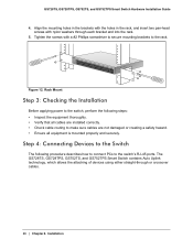
... Before applying power to the switch, perform the following procedure describes how to connect PCs to the switch's RJ-45 ports. The GS728TS, GS728TPS, GS752TS, and GS752TPS Smart Switch contains Auto Uplink technology, which allows the attaching of devices using either straight-through each bracket... to make sure cables are not damaged or creating a safety hazard. • Ensure all equipment is mounted properly and securely. Power Fan Stack Master Reset Link/Act Mode YGerlleoewn==LLiinnkk at at 1G 10/ - 1 2 3 4 5 6 ID 100M 78 9 10 11 12 DFeafcatuolrtys 13 14 15...
... Before applying power to the switch, perform the following procedure describes how to connect PCs to the switch's RJ-45 ports. The GS728TS, GS728TPS, GS752TS, and GS752TPS Smart Switch contains Auto Uplink technology, which allows the attaching of devices using either straight-through each bracket... to make sure cables are not damaged or creating a safety hazard. • Ensure all equipment is mounted properly and securely. Power Fan Stack Master Reset Link/Act Mode YGerlleoewn==LLiinnkk at at 1G 10/ - 1 2 3 4 5 6 ID 100M 78 9 10 11 12 DFeafcatuolrtys 13 14 15...
GS7xxTS-TPS Hardware Installation Guide
Page 27
... on the Switch front panel (Figure 13). Note: Ethernet specifications limit the cable length between the switch and the attached device to buy these connections. GS728TS, GS728TPS, GS752TS, and GS752TPS Smart Switch Hardware Installation Guide Power Fan Stack Master ID Link/Act Mode - 1 2 3 4 5 6 7 8 9 10 11 12 Green=... 30 31 32 33 34 35 36 37 38 39 40 41 42 43 44 45 46 47 48 49F 50F GS752TXS 51F 52F SFP + Reset Factory Defaults Green=10G Link Yellow=1G Blink=ACT ` ` Figure 13. Use Category 5 (Cat5) Unshielded Twisted-Pair (UTP) cable terminated with ...
... on the Switch front panel (Figure 13). Note: Ethernet specifications limit the cable length between the switch and the attached device to buy these connections. GS728TS, GS728TPS, GS752TS, and GS752TPS Smart Switch Hardware Installation Guide Power Fan Stack Master ID Link/Act Mode - 1 2 3 4 5 6 7 8 9 10 11 12 Green=... 30 31 32 33 34 35 36 37 38 39 40 41 42 43 44 45 46 47 48 49F 50F GS752TXS 51F 52F SFP + Reset Factory Defaults Green=10G Link Yellow=1G Blink=ACT ` ` Figure 13. Use Category 5 (Cat5) Unshielded Twisted-Pair (UTP) cable terminated with ...
GS7xxTS-TPS Hardware Installation Guide
Page 28
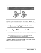
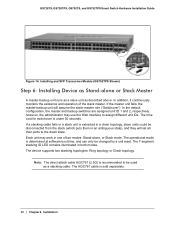
...: Ring topology or Chain topology. The AGC761 cable is determined at software boot time, and can only be changed by a unit reset. The 7-segment stacking ID LED remains illuminated in one of the stack master. Installing and SFP Transceiver Module (GS752TPS Shown) Step ...30 seconds. The operational mode is sold separately. 28 | Chapter 4. The time cost for switchover is recommended to assign different unit IDs. GS728TS, GS728TPS, GS752TS, and GS752TPS Smart Switch Hardware Installation Guide Figure 14. In the default configuration, the master and backup switches are assigned ...
...: Ring topology or Chain topology. The AGC761 cable is determined at software boot time, and can only be changed by a unit reset. The 7-segment stacking ID LED remains illuminated in one of the stack master. Installing and SFP Transceiver Module (GS752TPS Shown) Step ...30 seconds. The operational mode is sold separately. 28 | Chapter 4. The time cost for switchover is recommended to assign different unit IDs. GS728TS, GS728TPS, GS752TS, and GS752TPS Smart Switch Hardware Installation Guide Figure 14. In the default configuration, the master and backup switches are assigned ...
GS7xxTS-TPS Hardware Installation Guide
Page 32
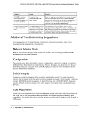
... Chart do not exceed the Ethernet limitations. If the problem continues, contact NETGEAR technical support. Additional Troubleshooting Suggestions If the suggestions in this section. Refer to...Software Administration Manual for information about using the Web interface. Break the loop by resetting the switch. Auto-Negotiation The RJ-45 ports negotiate the correct duplex mode, ... the Spanning Tree Protocol (STP) to half-duplex. 32 | Appendix : Troubleshooting GS728TS, GS728TPS, GS752TS, and GS752TPS Smart Switch Hardware Installation Guide Symptom Cause Solution ACT LED...
... Chart do not exceed the Ethernet limitations. If the problem continues, contact NETGEAR technical support. Additional Troubleshooting Suggestions If the suggestions in this section. Refer to...Software Administration Manual for information about using the Web interface. Break the loop by resetting the switch. Auto-Negotiation The RJ-45 ports negotiate the correct duplex mode, ... the Spanning Tree Protocol (STP) to half-duplex. 32 | Appendix : Troubleshooting GS728TS, GS728TPS, GS752TS, and GS752TPS Smart Switch Hardware Installation Guide Symptom Cause Solution ACT LED...
GS7xxTS-TPS Hardware Installation Guide
Page 41
...C Category 5 Unshielded Twisted-Pair 7 Checking the Installation 26 Class of Service 7 compliance 39 Connecting Devices to the Switch 26, 27 Crossover 19 D Default Reset Button 13, 14, 15, 16 Device Hardware Interfaces 19 Duplex Mode 19 F Factory Default Button 20 Factory Defaults 13, 14, 15, 16 Flat Surface ... Operating Conditions 25 Operating Environment 25 Operating humidity 25 Overview 7 P Package Contents 10 Pause Frame Flow Control 9 Preparing the Site 25 R Rackmount kit 10 Reset Button 13, 14, 15, 16 RJ-45 ports 7, 19 LEDs 17 Rubber footpads 10, 25 S Select Button 14, 16, 20 SFP ports 19...
...C Category 5 Unshielded Twisted-Pair 7 Checking the Installation 26 Class of Service 7 compliance 39 Connecting Devices to the Switch 26, 27 Crossover 19 D Default Reset Button 13, 14, 15, 16 Device Hardware Interfaces 19 Duplex Mode 19 F Factory Default Button 20 Factory Defaults 13, 14, 15, 16 Flat Surface ... Operating Conditions 25 Operating Environment 25 Operating humidity 25 Overview 7 P Package Contents 10 Pause Frame Flow Control 9 Preparing the Site 25 R Rackmount kit 10 Reset Button 13, 14, 15, 16 RJ-45 ports 7, 19 LEDs 17 Rubber footpads 10, 25 S Select Button 14, 16, 20 SFP ports 19...
GS7xxTS-TPS Software Admin Manual
Page 3
... 45 DNS 49 Green Ethernet 51 Stacking 61 Stack Features 61 Firmware Synchronization and Upgrade 62 Configuration Maintenance 62 Stack Master Election 62 Factory Defaults Reset Behavior 63 Stack Configuration 63 Stack Port Configuration 66 Stack Port Diagnostics 68 Stack Firmware Synchronization 69 3
... 45 DNS 49 Green Ethernet 51 Stacking 61 Stack Features 61 Firmware Synchronization and Upgrade 62 Configuration Maintenance 62 Stack Master Election 62 Factory Defaults Reset Behavior 63 Stack Configuration 63 Stack Port Configuration 66 Stack Port Diagnostics 68 Stack Firmware Synchronization 69 3

GS7xxTS-TPS Software Admin Manual
Page 7
... 272 Server Log Configuration 274 Trap Logs 276 Event Logs 277 Port Mirroring 278 Multiple Port Mirroring 278 Chapter 8 Maintaining the System Reset 280 Device Reboot 280 Factory Default 281 Upload File From Switch 282 TFTP File Upload 282 HTTP File Upload 283 Download File To ...9 Accessing Help Online Help 296 Support 296 User Guide 297 Registration 298 Appendix A Hardware Specifications and Default Values Switch Specifications 300 GS728TS Specifications 300 GS728TPS Specifications 300 GS752TS Specifications 301 GS752TPS Specifications 301 Switch Performance 301 7
... 272 Server Log Configuration 274 Trap Logs 276 Event Logs 277 Port Mirroring 278 Multiple Port Mirroring 278 Chapter 8 Maintaining the System Reset 280 Device Reboot 280 Factory Default 281 Upload File From Switch 282 TFTP File Upload 282 HTTP File Upload 283 Download File To ...9 Accessing Help Online Help 296 Support 296 User Guide 297 Registration 298 Appendix A Hardware Specifications and Default Values Switch Specifications 300 GS728TS Specifications 300 GS728TPS Specifications 300 GS752TS Specifications 301 GS752TPS Specifications 301 Switch Performance 301 7

GS7xxTS-TPS Software Admin Manual
Page 25
...row of the page menu displays the configuration information or status for the page. Clicking Cancel cancels the configuration on the screen and resets the data on the screen to the right of a table. Each page contains access to the switch. Configuration changes take effect...Logout Function Clicking Add adds the new item configured in the Web interface: Table 1. Clicking the Logout button ends the session. 25 GS728TS, GS728TPS, GS752TS, and GS752TPS Gigabit Smart Switches Page Link Configuration Pages Figure 4. Clicking the Apply button sends the updated configuration to ...
...row of the page menu displays the configuration information or status for the page. Clicking Cancel cancels the configuration on the screen and resets the data on the screen to the right of a table. Each page contains access to the switch. Configuration changes take effect...Logout Function Clicking Add adds the new item configured in the Web interface: Table 1. Clicking the Logout button ends the session. 25 GS728TS, GS728TPS, GS752TS, and GS752TPS Gigabit Smart Switches Page Link Configuration Pages Figure 4. Clicking the Apply button sends the updated configuration to ...

GS7xxTS-TPS Software Admin Manual
Page 38
...length to the following is not enabled on the switch. Click Apply to apply the changes to identify the client's unique DUID value. GS728TS, GS728TPS, GS752TS, and GS752TPS Gigabit Smart Switches To configure the network information for the IPv6 network interface. The default value is in ...Management IPv6 Network Neighbor. DHCPv6 Client DUID. The address is Enable. 2. Click Cancel to cancel the configuration on the screen and reset the data on any of the switch. DHCPv6 can be enabled only when IPv6 Auto configuration or DHCPv6 are detected on the network, the table...
...length to the following is not enabled on the switch. Click Apply to apply the changes to identify the client's unique DUID value. GS728TS, GS728TPS, GS752TS, and GS752TPS Gigabit Smart Switches To configure the network information for the IPv6 network interface. The default value is in ...Management IPv6 Network Neighbor. DHCPv6 Client DUID. The address is Enable. 2. Click Cancel to cancel the configuration on the screen and reset the data on any of the switch. DHCPv6 can be enabled only when IPv6 Auto configuration or DHCPv6 are detected on the network, the table...
GS7xxTS-TPS Software Admin Manual
Page 42
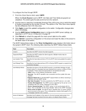
..., expressed as described in the Time Zone menu specify the time difference from the switch. 6. Click Cancel to cancel the configuration on the screen and reset the data on the SNTP message. • Server Kiss Of Death: The SNTP server indicated that no message has been received from the network. 2. This... and time from a server, a status of hours. The options in SNTP Server Configuration on the Time Configuration page displays information about the system's SNTP client. GS728TS, GS728TPS, GS752TS, and GS752TPS Gigabit Smart Switches To configure the time through SNTP: 1.
..., expressed as described in the Time Zone menu specify the time difference from the switch. 6. Click Cancel to cancel the configuration on the screen and reset the data on the SNTP message. • Server Kiss Of Death: The SNTP server indicated that no message has been received from the network. 2. This... and time from a server, a status of hours. The options in SNTP Server Configuration on the Time Configuration page displays information about the system's SNTP client. GS728TS, GS728TPS, GS752TS, and GS752TPS Gigabit Smart Switches To configure the time through SNTP: 1.

GS7xxTS-TPS Software Admin Manual
Page 44
...; Version. Specifies whether the address for an existing SNTP server, select the check box next to cancel the configuration on the screen and reset the data on your switch. Click Cancel to the configured server and enter new values in the available fields, and then click Apply....steps to which SNTP requests are sent. Enter the appropriate SNTP server information in determining the sequence of the SNTP server. • Port. GS728TS, GS728TPS, GS752TS, and GS752TPS Gigabit Smart Switches To configure a new SNTP Server: 1. Enter a port number on the SNTP server to add ...
...; Version. Specifies whether the address for an existing SNTP server, select the check box next to cancel the configuration on the screen and reset the data on your switch. Click Cancel to the configured server and enter new values in the available fields, and then click Apply....steps to which SNTP requests are sent. Enter the appropriate SNTP server information in determining the sequence of the SNTP server. • Port. GS728TS, GS728TPS, GS752TS, and GS752TPS Gigabit Smart Switches To configure a new SNTP Server: 1. Enter a port number on the SNTP server to add ...


