Netgear M4100-12GF Support and Manuals
Get Help and Manuals for this Netgear item
View All Support Options Below
Free Netgear M4100-12GF manuals!
Problems with Netgear M4100-12GF?
Ask a Question
Free Netgear M4100-12GF manuals!
Problems with Netgear M4100-12GF?
Ask a Question
Netgear M4100-12GF Videos

M4100-12GF NETGEAR Switch at Genisys
Duration: :33
Total Views: 2
Duration: :33
Total Views: 2
Popular Netgear M4100-12GF Manual Pages
Hardware Installation Guide - Page 2
...Microsoft Corporation. You must register your product before you for selecting NETGEAR products. NETGEAR Managed Switch
Support
Thank you can use it to register your product at http://support.netgear.com/general/contact/default.aspx. NETGEAR recommends registering your product and use NETGEAR telephone support.
After installing your device, locate the serial number on the label of your...
Hardware Installation Guide - Page 3
... the M4100-D12G or M4100-D10-PoE Using Magnets 19 Check the Installation 20 Connect to Power and Check the LEDs 20 SFP Modules 21 Connect Equipment to the Switch 22 RJ-45 Ports 22 Connect a Console to the Switch 22
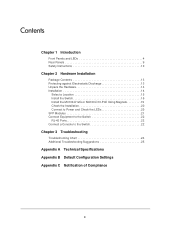
Chapter 3 Troubleshooting
Troubleshooting Chart 24 Additional Troubleshooting Suggestions 25
Appendix A Technical Specifications Appendix B Default Configuration Settings...
Hardware Installation Guide - Page 4

... solutions. Front Panels and LEDs
The following :
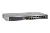
M4100-26G M4100-50G M4100-26-POE M4100-26G-POE M4100-50G-POE+ M4100-50-POE M4100-D10-POE M4100-D12G M4100-12GF M4100-D12G-POE+ M4100-24G-POE+ M4100-12G-POE+
This guide describes hardware installation and basic troubleshooting for each product, visit the NETGEAR website at http://www.netgear.com. These switches can use to eliminate bottlenecks...
Hardware Installation Guide - Page 7

NETGEAR Managed Switch
Power Fan PD MaxPoE
Reset
USB
PoE (Max 30W per port): OFF = No PD
Green = PoE Powered Yellow =...SPD/Link/ACT mode: Green = 1G
Yellow = 10/100M Blink = ACT
LEDs USB port
Reset button
Figure 9. M4100-12GF front panel
POE ports
SPD
Link/ACT
SPD/Link/ACT
RJ45 ports
M4100-12GF
SFP Green = 1G Yellow = 10/100M
Link/Act mode OFF = No Link Green = Link Blinking = ACT...
Hardware Installation Guide - Page 8

...Solid yellow: The fan has failed. Off: RPS disconnected. Note: Only for M4100-D12G, -24G-POE, D12G-POE, 12G-POE+, -12GF
Solid yellow: Indicates less than 7 watts of proper voltage (44 VDC-57 ...Indicates the PoE MAX LED was active in stopping power to PSE getting 802.3at specified power. NETGEAR Managed Switch
Table 1. Blinking yellow: Power module is present but has failed. Solid green: RPS ...
Hardware Installation Guide - Page 9

... (only for M4100-26G, 50G, 26-POE, 26G-POE, 50G-POE+, 50-POE, 12GF, 24G-POE+, and 12G-POE+), and a standard AC power receptacle for the supplied power cord. M4100-26G, 50G,...power from PSE successfully. Blinking yellow: Packet transmission or reception is established on the port. NETGEAR Managed Switch
Table 1. Off: No link is occurring on the port.
Solid green: A ...
Hardware Installation Guide - Page 10

... safety and to help protect your system documentation.
10 M4100-D12G-POE+ rear panel
AC power connector
Safety Instructions
Use the following precautions.
• Observe and follow service markings. - M4100-D10-POE and M4100-D12G rear panels
Console port
RPS
Lock
power supply
connector
Figure 15.
NETGEAR Managed Switch
Console switch
Console ports
Lock
Power adapter...
Hardware Installation Guide - Page 13

ProSafe M4100 Managed Switch Installation Guide - This hardware installation guide • ProSafe NMS200 Network Management System 30-day trial DVD
Protecting against Electrostatic Discharge
WARNING! Hardware Installation
2
This chapter explains how to install the hardware for the SFP sockets • Rack-mounting kit • Wall-mounting kit (M4100-D10-POE, M4100-D12G, and M4100-D12G-POE+ ...
Hardware Installation Guide - Page 16

...-inch rack-mount kit supplied with four self-adhesive rubber footpads. To install your switch in a rack you install your switch. NETGEAR Managed Switch
Install the Switch
You can install the switch on a flat surface or in a Rack
Note: The M4100-D10-PoE, M4100-D12G, and M4100-D12G-POE+ are not rack mountable. Stick one rubber footpad on...
Hardware Installation Guide - Page 20

... device used does not support IEEE802.3at, theses switches might not operate correctly.
3. Connect one end of the AC power adapter cable (M4100-DG12 or M4100-D10-PoE) or the
AC power cord to ensure that cables are installed correctly. 3. These switches can turn off switch. NETGEAR Managed Switch
Check the Installation
Before you connect the...
Hardware Installation Guide - Page 21

...Installation 21 For more information, see Troubleshooting on the front panel of the M4100-D12G and M4100-D12G-POE+ blinks green, port 1 is good.
Check the PoE device specification... and that the power source is connected to ensure that it supports IEEE802.3at. Note: Use only optical transceiver modules that are...NETGEAR Managed Switch
• If the POST fails, the Power LED blinks yellow.
Hardware Installation Guide - Page 23

... document and in PDF format on the Resource CD). • ProSafe Managed Switch Command-Line Interface (CLI) User Manual: Gives detailed examples of the cable to use the CLI. • ProSafe M4100 and M7100 Managed Switches Software Administration Manual: Describes configuration tasks. Connect the other end of how to a workstation or terminal. 4. The following settings: • Baud...
Hardware Installation Guide - Page 25

If the device does not support autonegotiation, the switch determines only the speed correctly and the duplex mode defaults to the troubleshooting suggestions in working condition and the software driver has been installed. • Configuration: If problems occur after you change the network configuration, restore the original connections. Then find the problem by making the changes, one step...
Hardware Installation Guide - Page 27
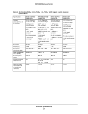
... Type A connector RS-232 console port 1 USB mini B console port
48 Gbps 4.368 440 x 257 x 43.2
M4100-D12G-POE+ M4100-12G-POE+
(GSM5212P)
(GSM7212P)
M4100-12GF (GSM7212F)
12 RJ-45 ports for 10/100/1000 Mbps
12 RJ-45 ports for 10/100/1000 Mbps
2 SFP ports for... dB @ 25dC with AC mode 0dB with PD mode
167.00
50.3 452.00
48 161.00
Technical Specifications 27 NETGEAR Managed Switch
Table 5.
Hardware Installation Guide - Page 32

NETGEAR Managed Switch
Table 8. M4100 Series switch default settings (Continued)
Feature GMRP IP routing MAC address aging SNMP community DHCP Server VLAN Ingress filtering IP multicast filtering 802.1x Port Security Auto Install LLDP LLDP-MED ISDP
Default Setting Disabled Disabled 300 seconds public (read-only access), private (read/write access) Disabled Enabled Disabled Disabled Disabled ...
Netgear M4100-12GF Reviews
We have not received any reviews for Netgear yet.