Hardware Installation Guide
Page 2
... NETGEAR products. Trademarks NETGEAR, the NETGEAR logo, ProSafe, Smart Wizard, and Auto Uplink are registered trademarks of Microsoft Corporation. After installing your product at http://support.netgear.com/general/contact/default.aspx. Phone (Other Countries): Check the list of your product and use NETGEAR telephone support. Microsoft, Windows, Windows NT, and Vista are trademarks or registered trademarks of their respective holders. For product updates and web support, visit http://support.netgear.com. Revision History Publication Part Number...
... NETGEAR products. Trademarks NETGEAR, the NETGEAR logo, ProSafe, Smart Wizard, and Auto Uplink are registered trademarks of Microsoft Corporation. After installing your product at http://support.netgear.com/general/contact/default.aspx. Phone (Other Countries): Check the list of your product and use NETGEAR telephone support. Microsoft, Windows, Windows NT, and Vista are trademarks or registered trademarks of their respective holders. For product updates and web support, visit http://support.netgear.com. Revision History Publication Part Number...
Hardware Installation Guide
Page 3
... 2 Hardware Installation Package Contents 13 Protecting against Electrostatic Discharge 13 Unpack the Hardware 14 Installation 14 Select a Location 15 Install the Switch 16 Install the M4100-D12G or M4100-D10-PoE Using Magnets 19 Check the Installation 20 Connect to Power and Check the LEDs 20 SFP Modules 21 Connect Equipment to the Switch 22 RJ-45 Ports 22 Connect a Console to the Switch 22 Chapter 3 Troubleshooting Troubleshooting Chart 24 Additional Troubleshooting Suggestions 25 Appendix A Technical Specifications Appendix B Default Configuration Settings Appendix...
... 2 Hardware Installation Package Contents 13 Protecting against Electrostatic Discharge 13 Unpack the Hardware 14 Installation 14 Select a Location 15 Install the Switch 16 Install the M4100-D12G or M4100-D10-PoE Using Magnets 19 Check the Installation 20 Connect to Power and Check the LEDs 20 SFP Modules 21 Connect Equipment to the Switch 22 RJ-45 Ports 22 Connect a Console to the Switch 22 Chapter 3 Troubleshooting Troubleshooting Chart 24 Additional Troubleshooting Suggestions 25 Appendix A Technical Specifications Appendix B Default Configuration Settings Appendix...

Hardware Installation Guide
Page 4
... panel contains LEDs, a Reset button, a USB flash port, RJ45 ports, copper (RJ-45)/fiber (SFP) combo ports, and USB console selection slide switch, and USB console port. 4 They include powerful management features that you can be freestanding, wall mounted, or rack mounted in a wiring closet or an equipment room. Front Panels and LEDs The following : M4100-26G M4100-50G M4100-26-POE M4100-26G-POE M4100-50G-POE+ M4100-50-POE M4100-D10-POE M4100-D12G M4100-12GF M4100-D12G-POE+ M4100-24G-POE+ M4100-12G-POE+ This guide describes hardware installation and basic troubleshooting for each...
... panel contains LEDs, a Reset button, a USB flash port, RJ45 ports, copper (RJ-45)/fiber (SFP) combo ports, and USB console selection slide switch, and USB console port. 4 They include powerful management features that you can be freestanding, wall mounted, or rack mounted in a wiring closet or an equipment room. Front Panels and LEDs The following : M4100-26G M4100-50G M4100-26-POE M4100-26G-POE M4100-50G-POE+ M4100-50-POE M4100-D10-POE M4100-D12G M4100-12GF M4100-D12G-POE+ M4100-24G-POE+ M4100-12G-POE+ This guide describes hardware installation and basic troubleshooting for each...

Hardware Installation Guide
Page 5
M4100-50-POE front panel POE ports RJ-45 ports SFP ports 5 M4100-26G front panel RJ-45 ports SFP ports Combo Ports Power Fan RPS Reset USB RJ45 SPD/Link/ACT mode: Green = 1G Yellow = 10/100M Blink = ACT LEDs USB port Reset button Figure 2. M4100-50G front panel RJ-45 ports SFP SPD/Link/ACT mode: Green = Link at 1G Yellow = Link at 100M Blink = ACT SFP ports LEDs USB port Reset button Figure 3. M4100-26-POE front panel POE ports RJ-45 ports SFP ports LEDs USB port Reset button Figure 4. NETGEAR Managed Switch LEDs USB port Reset button Figure 1.
M4100-50-POE front panel POE ports RJ-45 ports SFP ports 5 M4100-26G front panel RJ-45 ports SFP ports Combo Ports Power Fan RPS Reset USB RJ45 SPD/Link/ACT mode: Green = 1G Yellow = 10/100M Blink = ACT LEDs USB port Reset button Figure 2. M4100-50G front panel RJ-45 ports SFP SPD/Link/ACT mode: Green = Link at 1G Yellow = Link at 100M Blink = ACT SFP ports LEDs USB port Reset button Figure 3. M4100-26-POE front panel POE ports RJ-45 ports SFP ports LEDs USB port Reset button Figure 4. NETGEAR Managed Switch LEDs USB port Reset button Figure 1.

Hardware Installation Guide
Page 7
...ports M4100-12GF SFP Green = 1G Yellow = 10/100M Link/Act mode OFF = No Link Green = Link Blinking = ACT USB DB9 Console(USB) 115200,N,8,1 Mini Console USB prt switch 7 M4100-24G-POE+ front panel SPD/Link/ACT M4100-24G-POE+ SFP SPD/Link/ACT mode Green = Link at 1G Yellow = Link at 100M Blink = ACT SPD/Link/ACT LEDs USB Port Reset button Figure 12. M4100-D12G-POE+ front panel M4100-D12G-POE+ SFP SPD/Link/ACT mode Green = Link at 1G Yellow = Link at 100M Blink = ACT SPD/Link/ACT USB DB9 Console(USB) 115200,N,8,1 Console POE ports Mini switch SFP ports USB prt Power Fan...
...ports M4100-12GF SFP Green = 1G Yellow = 10/100M Link/Act mode OFF = No Link Green = Link Blinking = ACT USB DB9 Console(USB) 115200,N,8,1 Mini Console USB prt switch 7 M4100-24G-POE+ front panel SPD/Link/ACT M4100-24G-POE+ SFP SPD/Link/ACT mode Green = Link at 1G Yellow = Link at 100M Blink = ACT SPD/Link/ACT LEDs USB Port Reset button Figure 12. M4100-D12G-POE+ front panel M4100-D12G-POE+ SFP SPD/Link/ACT mode Green = Link at 1G Yellow = Link at 100M Blink = ACT SPD/Link/ACT USB DB9 Console(USB) 115200,N,8,1 Console POE ports Mini switch SFP ports USB prt Power Fan...

Hardware Installation Guide
Page 8
... least 7 watts of PoE power is established on the port. Solid yellow: The fan has failed. Off: No link is available. Note: Only for another device. NETGEAR Managed Switch Table 1. Off: Power is operating normally. Solid green: The fan is disconnected. Solid green: RPS connected (using internal power supply's power). Blinking yellow: RPS is connected to PSE getting 802.3af specified power. Note: Only for M4100-D12G, -24G-POE, D12G-POE, 12G-POE+, -12GF Solid yellow: Indicates...
... least 7 watts of PoE power is established on the port. Solid yellow: The fan has failed. Off: No link is available. Note: Only for another device. NETGEAR Managed Switch Table 1. Off: Power is operating normally. Solid green: The fan is disconnected. Solid green: RPS connected (using internal power supply's power). Blinking yellow: RPS is connected to PSE getting 802.3af specified power. Note: Only for M4100-D12G, -24G-POE, D12G-POE, 12G-POE+, -12GF Solid yellow: Indicates...

Hardware Installation Guide
Page 9
...: If combo port media changes to copper, the SFP port LED changes to off status. Mini USB port Console port RPS power supply connector Lock AC power connector Figure 13. M4100-26G, 50G, 26-POE, 26G-POE, 50G-POE+, and 50-POE rear panels 9 NETGEAR Managed Switch Table 1. Note: If a combo port media changes to fiber, the copper port LED changes to off status. SPD/Link/ACT (SFP port) Off: No SFP/SFP+ module link is established on the port. Blinking green: Packets transmission or reception is connected but connection has failed. PoE-PD Off...
...: If combo port media changes to copper, the SFP port LED changes to off status. Mini USB port Console port RPS power supply connector Lock AC power connector Figure 13. M4100-26G, 50G, 26-POE, 26G-POE, 50G-POE+, and 50-POE rear panels 9 NETGEAR Managed Switch Table 1. Note: If a combo port media changes to fiber, the copper port LED changes to off status. SPD/Link/ACT (SFP port) Off: No SFP/SFP+ module link is established on the port. Blinking green: Packets transmission or reception is connected but connection has failed. PoE-PD Off...

Hardware Installation Guide
Page 10
... guidelines to ensure your own personal safety and to help protect your system documentation. 10 M4100-12GF, 24G-POE+, 12G-POE+ rear panel AC power connector Lock Console port Figure 16. Do not service any product except as explained in your system from potential damage. NETGEAR Managed Switch Console switch Console ports Lock Power adapter connector Figure 14. M4100-D10-POE and M4100-D12G rear panels Console port RPS Lock power supply connector Figure 15.
... guidelines to ensure your own personal safety and to help protect your system documentation. 10 M4100-12GF, 24G-POE+, 12G-POE+ rear panel AC power connector Lock Console port Figure 16. Do not service any product except as explained in your system from potential damage. NETGEAR Managed Switch Console switch Console ports Lock Power adapter connector Figure 14. M4100-D10-POE and M4100-D12G rear panels Console port RPS Lock power supply connector Figure 15.
Hardware Installation Guide
Page 11
... be rated for the product and for use in your country. The power cable must use an extension cable, use adapter plugs or remove the grounding prong from a cable. If you have not been provided with the power available in your location. • Use only approved power cables. NETGEAR Managed Switch - The power cable, extension cable, or plug is approved for the voltage and current marked on the power supply is set to...
... be rated for the product and for use in your country. The power cable must use an extension cable, use adapter plugs or remove the grounding prong from a cable. If you have not been provided with the power available in your location. • Use only approved power cables. NETGEAR Managed Switch - The power cable, extension cable, or plug is approved for the voltage and current marked on the power supply is set to...

Hardware Installation Guide
Page 13
...Switch Command-Line Interface (CLI) User Manual - This hardware installation guide • ProSafe NMS200 Network Management System 30-day trial DVD Protecting against Electrostatic Discharge WARNING! To prevent static damage, discharge static electricity from your system. ProSafe M4100 and M7100 Managed Switches Software Administration Manual - 2. The package contains the following items: • Managed stackable switch with one mini B connector and one type A connector • Resource CD: The CD includes either these documents or links to access them: - ProSafe M4100 Managed Switch...
...Switch Command-Line Interface (CLI) User Manual - This hardware installation guide • ProSafe NMS200 Network Management System 30-day trial DVD Protecting against Electrostatic Discharge WARNING! To prevent static damage, discharge static electricity from your system. ProSafe M4100 and M7100 Managed Switches Software Administration Manual - 2. The package contains the following items: • Managed stackable switch with one mini B connector and one type A connector • Resource CD: The CD includes either these documents or links to access them: - ProSafe M4100 Managed Switch...
Hardware Installation Guide
Page 15
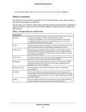
... Cabling • Desktop installations: Provide a flat table or shelf surface. • Rack-mount installations: Use a 19-inch (48.3-centimeter) EIA standard equipment rack that lets you access the front panel RJ-45 ports, view the front panel LEDs, and access the rear panel power connector. Install the switch in a standard 19-inch (48.26-centimeter) rack, wall mounted, or left freestanding (placed on page 20. Hardware Installation 15 The ambient switch...
... Cabling • Desktop installations: Provide a flat table or shelf surface. • Rack-mount installations: Use a 19-inch (48.3-centimeter) EIA standard equipment rack that lets you access the front panel RJ-45 ports, view the front panel LEDs, and access the rear panel power connector. Install the switch in a standard 19-inch (48.26-centimeter) rack, wall mounted, or left freestanding (placed on page 20. Hardware Installation 15 The ambient switch...

Hardware Installation Guide
Page 16
...) to allow for example, the use of the switch. To ensure this concern. • Reliable grounding. NETGEAR Managed Switch Install the Switch You can install the switch on a flat surface or in a Rack Note: The M4100-D10-PoE, M4100-D12G, and M4100-D12G-POE+ are not rack mountable. Install the Switch on the bottom of power strips). • Clearance. Install the Switch in a standard 19-inch rack. If the switch is not compromised. •...
...) to allow for example, the use of the switch. To ensure this concern. • Reliable grounding. NETGEAR Managed Switch Install the Switch You can install the switch on a flat surface or in a Rack Note: The M4100-D10-PoE, M4100-D12G, and M4100-D12G-POE+ are not rack mountable. Install the Switch on the bottom of power strips). • Clearance. Install the Switch in a standard 19-inch rack. If the switch is not compromised. •...

Hardware Installation Guide
Page 20
... power using the supplied power adapter. Hardware Installation 20 To apply AC power: 1. Note: Normally the M4100-D12G and M4100-D12G-POE+ will not create a safety hazard. 4. The LED should support IEEE802.3at so that all equipment is not available. NETGEAR Managed Switch Check the Installation Before you connect the power cord, select an AC outlet that is not controlled by a wall switch (which can provide full power to these switches to pass data. Check cable routing to the switch). Connect...
... power using the supplied power adapter. Hardware Installation 20 To apply AC power: 1. Note: Normally the M4100-D12G and M4100-D12G-POE+ will not create a safety hazard. 4. The LED should support IEEE802.3at so that all equipment is not available. NETGEAR Managed Switch Check the Installation Before you connect the power cord, select an AC outlet that is not controlled by a wall switch (which can provide full power to these switches to pass data. Check cable routing to the switch). Connect...

Hardware Installation Guide
Page 21
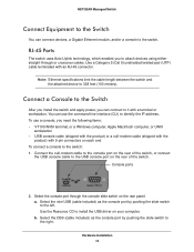
... insert an SFP module into the connector. SFP Modules SFP modules (sold separately) can be inserted directly into the switch port. 2. Note: Use only optical transceiver modules that are UL approved and that the module seats into the switch port: 1. Hardware Installation 21 If the Power LED does not light up, check that the power cable is good. Check the PoE device specification to a IEEE802.3af PoE device. NETGEAR Managed Switch • If the POST fails, the Power LED blinks yellow. Note...
... insert an SFP module into the connector. SFP Modules SFP modules (sold separately) can be inserted directly into the switch port. 2. Note: Use only optical transceiver modules that are UL approved and that the module seats into the switch port: 1. Hardware Installation 21 If the Power LED does not light up, check that the power cable is good. Check the PoE device specification to a IEEE802.3af PoE device. NETGEAR Managed Switch • If the POST fails, the Power LED blinks yellow. Note...
Hardware Installation Guide
Page 22
... command-line interface (CLI) to the switch: 1. Console ports 2. Hardware Installation 22 Use the Resource CD to install the USB driver on each end To connect a console to identify the IP address. Connect a Console to the Switch After you install the switch and apply power, you to the left. Select the DB9 (cable included) as the console port by pushing the slide switch to 328 feet (100 meters). Select the console port through or crossover cables. Note: Ethernet specifications limit the cable...
... command-line interface (CLI) to the switch: 1. Console ports 2. Hardware Installation 22 Use the Resource CD to install the USB driver on each end To connect a console to identify the IP address. Connect a Console to the Switch After you install the switch and apply power, you to the left. Select the DB9 (cable included) as the console port by pushing the slide switch to 328 feet (100 meters). Select the console port through or crossover cables. Note: Ethernet specifications limit the cable...

Hardware Installation Guide
Page 23
...; Stop bit: 1 • Flow control: none After you connect a console to a workstation or terminal. 4. Connect the other end of how to use a terminal-emulator such as both a print document and in PDF format on the Resource CD). • ProSafe Managed Switch Command-Line Interface (CLI) User Manual: Gives detailed examples of the cable to the switch, you attached a workstation, start a terminal emulation program. • Microsoft Windows users can use the CLI. • ProSafe M4100 and M7100 Managed Switches Software Administration Manual: Describes configuration tasks.
...; Stop bit: 1 • Flow control: none After you connect a console to a workstation or terminal. 4. Connect the other end of how to use a terminal-emulator such as both a print document and in PDF format on the Resource CD). • ProSafe Managed Switch Command-Line Interface (CLI) User Manual: Gives detailed examples of the cable to the switch, you attached a workstation, start a terminal emulation program. • Microsoft Windows users can use the CLI. • ProSafe M4100 and M7100 Managed Switches Software Administration Manual: Describes configuration tasks.
Hardware Installation Guide
Page 24
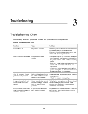
... ports. See Appendix A. • Check for the switch at both the switch and the connecting device. • Make sure that the plug is received. or full-duplex setting on • Make sure that the cabling is off . Be sure that all cables used are correct and comply with Ethernet specifications. 3. Troubleshooting 3 Troubleshooting Chart The following table lists symptoms, causes, and solutions to any networked device to possible problems. Table 3. Link LED...
... ports. See Appendix A. • Check for the switch at both the switch and the connecting device. • Make sure that the plug is received. or full-duplex setting on • Make sure that the cabling is off . Be sure that all cables used are correct and comply with Ethernet specifications. 3. Troubleshooting 3 Troubleshooting Chart The following table lists symptoms, causes, and solutions to any networked device to possible problems. Table 3. Link LED...

Hardware Installation Guide
Page 25
... network configuration, restore the original connections. If the device does not support autonegotiation, the switch determines only the speed correctly and the duplex mode defaults to the troubleshooting suggestions in this section. • Network adapter cards: Make sure that cable distances, repeater limits, and other end of the link supports autonegotiation. Troubleshooting 25 The fiber gigabit ports negotiate speed, duplex mode, and flow control if the attached device supports autonegotiation. To reset the switch, use the Tools > Reset command, or remove AC power...
... network configuration, restore the original connections. If the device does not support autonegotiation, the switch determines only the speed correctly and the duplex mode defaults to the troubleshooting suggestions in this section. • Network adapter cards: Make sure that cable distances, repeater limits, and other end of the link supports autonegotiation. Troubleshooting 25 The fiber gigabit ports negotiate speed, duplex mode, and flow control if the attached device supports autonegotiation. To reset the switch, use the Tools > Reset command, or remove AC power...
Hardware Installation Guide
Page 29
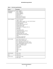
...; Broadcast storm control • Telnet sessions for management CPU (5) • Ping support • ARP support • Private enterprise MIB • Configuration file upload, download • Runtime image download • Command-line interface • Web-based graphic user interface • Simple Network Time Protocol (SNTP) • Syslog • SSLv3/TLSv1.0 web security • Secured Shell (SSHv1, v2) Layer 2 services • 802.1Q Static VLAN (Up to 1 K) • 802.1 p Class of Service (CoS) • 802.1D Spanning Tree Protocol (STP...
...; Broadcast storm control • Telnet sessions for management CPU (5) • Ping support • ARP support • Private enterprise MIB • Configuration file upload, download • Runtime image download • Command-line interface • Web-based graphic user interface • Simple Network Time Protocol (SNTP) • Syslog • SSLv3/TLSv1.0 web security • Secured Shell (SSHv1, v2) Layer 2 services • 802.1Q Static VLAN (Up to 1 K) • 802.1 p Class of Service (CoS) • 802.1D Spanning Tree Protocol (STP...

Hardware Installation Guide
Page 32
M4100 Series switch default settings (Continued) Feature GMRP IP routing MAC address aging SNMP community DHCP Server VLAN Ingress filtering IP multicast filtering 802.1x Port Security Auto Install LLDP LLDP-MED ISDP Default Setting Disabled Disabled 300 seconds public (read-only access), private (read/write access) Disabled Enabled Disabled Disabled Disabled Enabled Enabled Enabled Enabled Default Configuration Settings 32 NETGEAR Managed Switch Table 8.
M4100 Series switch default settings (Continued) Feature GMRP IP routing MAC address aging SNMP community DHCP Server VLAN Ingress filtering IP multicast filtering 802.1x Port Security Auto Install LLDP LLDP-MED ISDP Default Setting Disabled Disabled 300 seconds public (read-only access), private (read/write access) Disabled Enabled Disabled Disabled Disabled Enabled Enabled Enabled Enabled Default Configuration Settings 32 NETGEAR Managed Switch Table 8.


