FS726T User Manual
Page 16
...-Based Management Interface July 2005 The possible entries are several buttons that screen's data from table and refreshes screen data Restore the system factory default value. Smart Switch Series Software Manual There is a Help Menu in the system menu: • Switch Status • IP Access List • Setup •... Help Menu that discusses that button, you can use. The default setting for the port. If you click that page. Click the help to the part of Help Menu System Menu There are below: Browse: Refresh: Apply: Add: Delete: Factory Reset: Help: Locates a certain...
...-Based Management Interface July 2005 The possible entries are several buttons that screen's data from table and refreshes screen data Restore the system factory default value. Smart Switch Series Software Manual There is a Help Menu in the system menu: • Switch Status • IP Access List • Setup •... Help Menu that discusses that button, you can use. The default setting for the port. If you click that page. Click the help to the part of Help Menu System Menu There are below: Browse: Refresh: Apply: Add: Delete: Factory Reset: Help: Locates a certain...
GS724Tv2 Hardware manual
Page 3
... MBPS RJ-45 PORTS...8 SFP GBIC MODULE ...9 LED DESCRIPTIONS...9 RESET BUTTON...9 FACTORY DEFAULTS BUTTON...10 CHAPTER 3: APPLICATIONS...11 DESKTOP SWITCHING ...11 BACKBONE SWITCHING ...12 CHAPTER 4: INSTALLATION ...13 STEP 1: PREPARING THE SITE ...13 STEP 2: INSTALLING THE SWITCH ...13 STEP 3: CHECKING THE INSTALLATION ...14 STEP 4: CONNECTING DEVICES TO THE SWITCH ...14 STEP 5: INSTALLING AN SFP GBIC MODULE ...14 STEP...
... MBPS RJ-45 PORTS...8 SFP GBIC MODULE ...9 LED DESCRIPTIONS...9 RESET BUTTON...9 FACTORY DEFAULTS BUTTON...10 CHAPTER 3: APPLICATIONS...11 DESKTOP SWITCHING ...11 BACKBONE SWITCHING ...12 CHAPTER 4: INSTALLATION ...13 STEP 1: PREPARING THE SITE ...13 STEP 2: INSTALLING THE SWITCH ...13 STEP 3: CHECKING THE INSTALLATION ...14 STEP 4: CONNECTING DEVICES TO THE SWITCH ...14 STEP 5: INSTALLING AN SFP GBIC MODULE ...14 STEP...
GS724Tv2 Hardware manual
Page 6
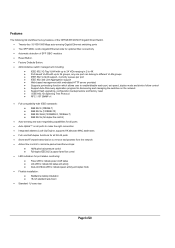
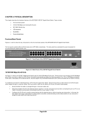
...NETGEAR GS724T Gigabit Smart Switch. • Twenty-four 10/100/1000 Mbps auto-sensing Gigabit Ethernet switching ports • Two SFP GBIC combo Gigabit Ethernet slots for optional fiber connectivity • Automatic detection of SFP GBIC modules • Reset Button. • Factory Defaults Button. • Administrative switch... control ♦ Support Auto-Discovery application program for discovering and managing the switches on the network ♦ Support flash upgrading, configuration backup/restore and factory reset ♦ IEEE 802.1D Spanning Tree Protocol ♦ RFC 1157 SNMP ...
...NETGEAR GS724T Gigabit Smart Switch. • Twenty-four 10/100/1000 Mbps auto-sensing Gigabit Ethernet switching ports • Two SFP GBIC combo Gigabit Ethernet slots for optional fiber connectivity • Automatic detection of SFP GBIC modules • Reset Button. • Factory Defaults Button. • Administrative switch... control ♦ Support Auto-Discovery application program for discovering and managing the switches on the network ♦ Support flash upgrading, configuration backup/restore and factory reset ♦ IEEE 802.1D Spanning Tree Protocol ♦ RFC 1157 SNMP ...
GS724Tv2 Hardware manual
Page 8
...back panel has a standard AC power receptacle for attaching devices, all RJ-45 ports support Auto Uplink. Front Panel of the NETGEAR GS724T Gigabit Smart Switch. These ports are auto-sensing 10/100/1000 Mbps ports: When you insert a cable into an RJ-45 port, the...45 ports • SFP GBIC Module bay • LED descriptions • Reset Button • Factory Defaults Button Front and Back Panels Figures 2-1 and 2-2 show the key components on the front and back panels of the GS724T Gigabit Smart Switch Figure 2-2. This technology lets you attach devices to use crossover or straight-...
...back panel has a standard AC power receptacle for attaching devices, all RJ-45 ports support Auto Uplink. Front Panel of the NETGEAR GS724T Gigabit Smart Switch. These ports are auto-sensing 10/100/1000 Mbps ports: When you insert a cable into an RJ-45 port, the...45 ports • SFP GBIC Module bay • LED descriptions • Reset Button • Factory Defaults Button Front and Back Panels Figures 2-1 and 2-2 show the key components on the front and back panels of the GS724T Gigabit Smart Switch Figure 2-2. This technology lets you attach devices to use crossover or straight-...
GS724Tv2 Hardware manual
Page 9
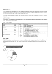
... active at any given time. Port has a valid link connection. The LEDs on the switch should go out and then come back on your network. LED Descriptions The front panel of the NETGEAR GS724T Gigabit Smart Switch has LEDs that is disconnected. Table 2-1 summarizes the LEDs on the port. Front Panel LEDs...link mode is established on the port A valid 1000Mbps link is established on the port Data transmission is established on the port Reset Button The GS724T has a Reset Button to turning the power off and back on the port. The module bays are plugged in at the same time. The ...
... active at any given time. Port has a valid link connection. The LEDs on the switch should go out and then come back on your network. LED Descriptions The front panel of the NETGEAR GS724T Gigabit Smart Switch has LEDs that is disconnected. Table 2-1 summarizes the LEDs on the port. Front Panel LEDs...link mode is established on the port A valid 1000Mbps link is established on the port Data transmission is established on the port Reset Button The GS724T has a Reset Button to turning the power off and back on the port. The module bays are plugged in at the same time. The ...


