
GS748TR Hardware manual
Page 13
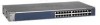
...NETGEAR GS724TR Smart Switch front panel: System LEDs Port LEDs Figure 2-1 10/100/1000M Ethernet Ports SFP Ports The front panel contains the following: • 24 RJ-45 connectors for 10/100/1000Mbps auto sensing Gigabit Ethernet switching ports. • Two SFP slots for SFP modules supporting 1000(1000Base-SX/LX)/100M SFP. • Reset... button to restart the device. • Recessed default reset button to restore the device back to the factory defaults...
...NETGEAR GS724TR Smart Switch front panel: System LEDs Port LEDs Figure 2-1 10/100/1000M Ethernet Ports SFP Ports The front panel contains the following: • 24 RJ-45 connectors for 10/100/1000Mbps auto sensing Gigabit Ethernet switching ports. • Two SFP slots for SFP modules supporting 1000(1000Base-SX/LX)/100M SFP. • Reset... button to restart the device. • Recessed default reset button to restore the device back to the factory defaults...

GS748TR Hardware manual
Page 14
...Smart Static Routing switch + 4 SFP Combo port switch. GS700TR Series Hardware Installation Guide • System LEDs Figure 2-2 illustrates the NETGEAR GS724TR Smart Switch back panel: Figure 2-2 RS-232 Power Connector The back panel contains the following : • 48 RJ-45 connectors for 10/100/1000Mbps auto sensing Gigabit Ethernet switching...SFP modules supporting 1000(1000Base-SX/LX)/100M SFP. • Reset button to restart the device. • Recessed default reset button to restore the device back to the factory defaults. • Port LEDs 2-6 Physical Description v1.0, December ...
...Smart Static Routing switch + 4 SFP Combo port switch. GS700TR Series Hardware Installation Guide • System LEDs Figure 2-2 illustrates the NETGEAR GS724TR Smart Switch back panel: Figure 2-2 RS-232 Power Connector The back panel contains the following : • 48 RJ-45 connectors for 10/100/1000Mbps auto sensing Gigabit Ethernet switching...SFP modules supporting 1000(1000Base-SX/LX)/100M SFP. • Reset button to restart the device. • Recessed default reset button to restore the device back to the factory defaults. • Port LEDs 2-6 Physical Description v1.0, December ...

GS748TR Hardware manual
Page 35
...2-6 100BASE-TX 1-2 10BASE-T 1-2 1U 1-3 8-pin 2-8 A AC Power 2-6, 2-7 AGM731F 2-9 AGM732F 2-9 AGM733 2-9 Applying AC Power 4-17 Attaching Switch to a Rack 4-15 Auto Sensing 1-2 Auto Uplink 2-8, 2-9 Auto-negotiating 1-2 Auto-sensing 2-8 B Back-pressure 1-3 Brackets 4-14 C Category 5...Switch 4-16 Copper 1-1 Crossover 2-8 D Default IP Address 4-18 Default Reset Button 2-5, 2-6 Device Hardware Interfaces 2-8 Duplex Mode 2-8 E Example of Desktop Switching 3-11 F Factory Default Button 2-9 Factory Defaults 2-5 Fan LED 2-8 Fiber Connectivity 1-1 Flat Surface 4-14 Full-duplex 1-2 G GBIC 1-2, 2-9 Gigabit ...
...2-6 100BASE-TX 1-2 10BASE-T 1-2 1U 1-3 8-pin 2-8 A AC Power 2-6, 2-7 AGM731F 2-9 AGM732F 2-9 AGM733 2-9 Applying AC Power 4-17 Attaching Switch to a Rack 4-15 Auto Sensing 1-2 Auto Uplink 2-8, 2-9 Auto-negotiating 1-2 Auto-sensing 2-8 B Back-pressure 1-3 Brackets 4-14 C Category 5...Switch 4-16 Copper 1-1 Crossover 2-8 D Default IP Address 4-18 Default Reset Button 2-5, 2-6 Device Hardware Interfaces 2-8 Duplex Mode 2-8 E Example of Desktop Switching 3-11 F Factory Default Button 2-9 Factory Defaults 2-5 Fan LED 2-8 Fiber Connectivity 1-1 Flat Surface 4-14 Full-duplex 1-2 G GBIC 1-2, 2-9 Gigabit ...

