GS724TP User Manual
Page 42
...; IP Gateways • Audio and video remote monitoring Powered Devices are devices that receive power from the device power supply, for enabling PoE on the device: 1. Click System > PoE > Basic > PoE Configuration. To configure PoE on the device, monitoring the current power usage, and enabling PoE traps. GS700TP Smart Switch Software Administration Manual Power over Ethernet can be used in the following fields...
...; IP Gateways • Audio and video remote monitoring Powered Devices are devices that receive power from the device power supply, for enabling PoE on the device: 1. Click System > PoE > Basic > PoE Configuration. To configure PoE on the device, monitoring the current power usage, and enabling PoE traps. GS700TP Smart Switch Software Administration Manual Power over Ethernet can be used in the following fields...

GS724TP User Manual
Page 43
...power source status. Displays the actual amount of the power used by the device. Enable PoE traps on the device. - The power supply unit is 1-99 percent. Select the PoE device trap state. For example, a power overload or a short circuit. • Nominal Power - The power supply... Usage Threshold - Enter the percentage of power consumed before an alarm is functioning, but an error has occurred. The power supply unit is the default value. 2. This is functioning. - GS700TP Smart Switch Software Administration Manual • Power Status - The field value is 95 ...
...power source status. Displays the actual amount of the power used by the device. Enable PoE traps on the device. - The power supply unit is 1-99 percent. Select the PoE device trap state. For example, a power overload or a short circuit. • Nominal Power - The power supply... Usage Threshold - Enter the percentage of power consumed before an alarm is functioning, but an error has occurred. The power supply unit is the default value. 2. This is functioning. - GS700TP Smart Switch Software Administration Manual • Power Status - The field value is 95 ...

GS724TP User Manual
Page 44
...; System Usage Threshold - The power supply unit is 1-99 percent. The field value is functioning. - The field value is functioning, but an error has occurred. The power supply unit is displayed in the provided field. 3. Enable PoE traps on the device. Enter the System Usage Threshold in Watts. • Consumed Power - GS700TP Smart Switch Software Administration Manual To...
...; System Usage Threshold - The power supply unit is 1-99 percent. The field value is functioning. - The field value is functioning, but an error has occurred. The power supply unit is displayed in the provided field. 3. Enable PoE traps on the device. Enter the System Usage Threshold in Watts. • Consumed Power - GS700TP Smart Switch Software Administration Manual To...
GS724TP User Manual
Page 45
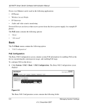
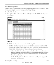
... protocol and provides power to the device using the PoE module. The PoE Port Configuration screen displays: Figure 3-8 The PoE Port Configuration screen contains the following fields: • Interface - This is connected to learn their classification. GS700TP Smart Switch Software Administration Manual PoE Port Configuration The PoE Interface Configuration screen contains system PoE information for which PoE parameters are defined...
... protocol and provides power to the device using the PoE module. The PoE Port Configuration screen displays: Figure 3-8 The PoE Port Configuration screen contains the following fields: • Interface - This is connected to learn their classification. GS700TP Smart Switch Software Administration Manual PoE Port Configuration The PoE Interface Configuration screen contains system PoE information for which PoE parameters are defined...
GS724TP User Manual
Page 46
GS700TP Smart Switch Software Administration Manual • Priority Level - Select the port priority if the power supply is 7.0 Watts. - Set the PoE priority level as high. • Class - Set the PoE priority level as low. The possible field values are : - The minimum power level at the Power Sourcing Equipment is low. The possible field values are : - The device is...
GS700TP Smart Switch Software Administration Manual • Priority Level - Select the port priority if the power supply is 7.0 Watts. - Set the PoE priority level as high. • Class - Set the PoE priority level as low. The possible field values are : - The minimum power level at the Power Sourcing Equipment is low. The possible field values are : - The device is...
GS724TP Hardware manual
Page 6
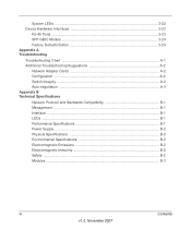
...24 Factory Defaults Button 3-24 Appendix A Troubleshooting Troubleshooting Chart A-1 Additional Troubleshooting Suggestions A-2 Network Adapter Cards A-2 Configuration ...A-2 Switch Integrity ...A-2 Auto-negotiation ...A-3 Appendix B Technical Specifications Network Protocol and Standards Compatibility B-1 Management ...B-1 Interface ...B-1 LEDs ...B-1 Performance Specifications B-1 Power Supply ...B-2 Physical Specifications B-2 Environmental Specifications B-2 Electromagnetic Emissions B-2 Electromagnetic Immunity B-2 Safety ...B-2 Modules ...B-3 vi Contents v1.0, November 2007
...24 Factory Defaults Button 3-24 Appendix A Troubleshooting Troubleshooting Chart A-1 Additional Troubleshooting Suggestions A-2 Network Adapter Cards A-2 Configuration ...A-2 Switch Integrity ...A-2 Auto-negotiation ...A-3 Appendix B Technical Specifications Network Protocol and Standards Compatibility B-1 Management ...B-1 Interface ...B-1 LEDs ...B-1 Performance Specifications B-1 Power Supply ...B-2 Physical Specifications B-2 Environmental Specifications B-2 Electromagnetic Emissions B-2 Electromagnetic Immunity B-2 Safety ...B-2 Modules ...B-3 vi Contents v1.0, November 2007
GS724TP Hardware manual
Page 13
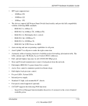
...learning function to build the packet-forwarding information table. Smart Power Managed function handles the power of each port in the event of limited available power. IEEE 802.3ab (1000Base-T) - IEEE 802....Netgear Smart Switch functionality and provide full compatibility with the following POE functions: - The table contains up to minimize packet loss/frame drops. • Half-duplex back-pressure control. • Per port LEDs, System LEDs. • Internal power supply. • Standard 1U high, rack mountable19" chassis. • Fan speed control supported (optional). • GS724TP...
...learning function to build the packet-forwarding information table. Smart Power Managed function handles the power of each port in the event of limited available power. IEEE 802.3ab (1000Base-T) - IEEE 802....Netgear Smart Switch functionality and provide full compatibility with the following POE functions: - The table contains up to minimize packet loss/frame drops. • Half-duplex back-pressure control. • Per port LEDs, System LEDs. • Internal power supply. • Standard 1U high, rack mountable19" chassis. • Fan speed control supported (optional). • GS724TP...

GS724TP Hardware manual
Page 16
...the Switch Step 5: Installing an SFP GBIC Module Step 6: Applying AC Power Step 7: Managing the Switch through a Web Browser or the PC Utility for your NETGEAR Smart Switch.... Chapter 2 Installation This chapter describes the installation procedures for Initial Configuration Step 1: Preparing the Site Before installing the switch, ensure the operating environment meets the requirements in a position that is also required. Table 2-1. The rack-mount kit supplied with the switch...
...the Switch Step 5: Installing an SFP GBIC Module Step 6: Applying AC Power Step 7: Managing the Switch through a Web Browser or the PC Utility for your NETGEAR Smart Switch.... Chapter 2 Installation This chapter describes the installation procedures for Initial Configuration Step 1: Preparing the Site Before installing the switch, ensure the operating environment meets the requirements in a position that is also required. Table 2-1. The rack-mount kit supplied with the switch...

GS724TP Hardware manual
Page 17
... the Switch The NETGEAR Smart Switch can accidentally turn off power to Figure 2-1). The rubber footpads cushion the switch against shock/vibrations. Power specifications for cooling. The installation location should have a maximum relative humidity of the installation location. Installing the Switch in a Rack To install the switch in ...nylon washers through each bracket and into the bracket mounting holes in the switch. 3. To perform this procedure, you need the 19-inch rack-mount kit supplied with four self-adhesive rubber footpads. Align the mounting holes in the brackets...
... the Switch The NETGEAR Smart Switch can accidentally turn off power to Figure 2-1). The rubber footpads cushion the switch against shock/vibrations. Power specifications for cooling. The installation location should have a maximum relative humidity of the installation location. Installing the Switch in a Rack To install the switch in ...nylon washers through each bracket and into the bracket mounting holes in the switch. 3. To perform this procedure, you need the 19-inch rack-mount kit supplied with four self-adhesive rubber footpads. Align the mounting holes in the brackets...

GS724TP Hardware manual
Page 20
... 6: Applying AC Power NETGEAR Smart Switch does not have an ON/OFF switch. The method of applying or removing AC power is by a wall switch, which can turn off power to the power receptacle on the switch's front panel is green. When applying power, the Power LED on the back of the supplied AC power adapter cable to the switch. If the Power LED does light...
... 6: Applying AC Power NETGEAR Smart Switch does not have an ON/OFF switch. The method of applying or removing AC power is by a wall switch, which can turn off power to the power receptacle on the switch's front panel is green. When applying power, the Power LED on the back of the supplied AC power adapter cable to the switch. If the Power LED does light...

GS724TP Hardware manual
Page 23
...NETGEAR GS748TP Smart Switch front panel: Figure 3-3 The front panel contains the following : • A 100-240VAC/50-60 Hz universal input, which is a 48-Port 10/100/1000M Smart PoE switch + 4 SFP Combo port switch. GS748TP Front and Back Panels Configuration The GS748TP is a standard AC power...8226; System LEDs Figure 3-2 illustrates the NETGEAR GS724TP Smart Switch back panel: Figure 3-2 The back panel contains the following : • 48 RJ-45 connectors for 10/100/1000Mbps auto sensing Gigabit Ethernet switching ports. • Four SFP slots for accommodating the supplied power cord.
...NETGEAR GS748TP Smart Switch front panel: Figure 3-3 The front panel contains the following : • A 100-240VAC/50-60 Hz universal input, which is a 48-Port 10/100/1000M Smart PoE switch + 4 SFP Combo port switch. GS748TP Front and Back Panels Configuration The GS748TP is a standard AC power...8226; System LEDs Figure 3-2 illustrates the NETGEAR GS724TP Smart Switch back panel: Figure 3-2 The back panel contains the following : • 48 RJ-45 connectors for 10/100/1000Mbps auto sensing Gigabit Ethernet switching ports. • Four SFP slots for accommodating the supplied power cord.
GS724TP Hardware manual
Page 24
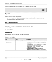
.../1000 Ports SPD/Link/ACT LED - LED Designations This section provides an explanation for accommodating the supplied power cord. GS700TP Hardware Installation Guide Figure 3-4 illustrates the NETGEAR GS724TP Smart Switch back panel: Figure 3-4 The back panel contains the following: • A 100-240VAC/50-...60 Hz universal input, which is a standard AC power receptacle for the following LED types: • Port ...
.../1000 Ports SPD/Link/ACT LED - LED Designations This section provides an explanation for accommodating the supplied power cord. GS700TP Hardware Installation Guide Figure 3-4 illustrates the NETGEAR GS724TP Smart Switch back panel: Figure 3-4 The back panel contains the following: • A 100-240VAC/50-...60 Hz universal input, which is a standard AC power receptacle for the following LED types: • Port ...

GS724TP Hardware manual
Page 25
...on PoE power circuit. •PoE power demand exceeds power available. •PoE current exceeds PD's Classification. •Out of PoE power is operating normally. A valid 100Mbps SFP module link is supplying power successfully. • Solid Yellow - System LEDs LED MAX POE LED 1~24/48 Port LED mode select LED Power ... of the following table describes the system LED designations. Indicates the PoE MAX LED was active in stopping power to the switch and is available. • Flashing Yellow - Indicates one of PoE power available for another device. • Solid Yellow - Table 3-2. ...
...on PoE power circuit. •PoE power demand exceeds power available. •PoE current exceeds PD's Classification. •Out of PoE power is operating normally. A valid 100Mbps SFP module link is supplying power successfully. • Solid Yellow - System LEDs LED MAX POE LED 1~24/48 Port LED mode select LED Power ... of the following table describes the system LED designations. Indicates the PoE MAX LED was active in stopping power to the switch and is available. • Flashing Yellow - Indicates one of PoE power available for another device. • Solid Yellow - Table 3-2. ...
GS724TP Hardware manual
Page 32
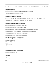
Mean Time Between Failure (MTBF): 165,589 hours for GS724TP, 147,558 hours for GS748TP Power Supply Power Consumption: 260W for GS724TP, 570W for GS748TP 100-240VAC/50-60 Hz universal input Physical Specifications Dimensions (H x W x D): GS724TP/GS724TP: 1.6 x 17.3 x 8.1 / 43 x 440 x 205 (in/mm) Weight: 6.33 / 2.87 (lbs/kg), GS748TP : 11.27 / 5.11 (lbs/kg) Environmental Specifications Operating temperature...
Mean Time Between Failure (MTBF): 165,589 hours for GS724TP, 147,558 hours for GS748TP Power Supply Power Consumption: 260W for GS724TP, 570W for GS748TP 100-240VAC/50-60 Hz universal input Physical Specifications Dimensions (H x W x D): GS724TP/GS724TP: 1.6 x 17.3 x 8.1 / 43 x 440 x 205 (in/mm) Weight: 6.33 / 2.87 (lbs/kg), GS748TP : 11.27 / 5.11 (lbs/kg) Environmental Specifications Operating temperature...

GS724TP Hardware manual
Page 35
... an SFP GBIC Module 4-16 Installing the Switch 4-14 Internal Power Supply 1-3 L LED Designations 2-8 Link/ACT LED 2-8 Low Latency 1-2 M MAC 1-3 MAX POE LED 2-9 Media Access Control 1-3 Mounting Holes 4-14 N Nylon Washers 4-14 O ON/OFF switch 4-17 Operating Conditions 4-14 Operating Environment 4-13...Power cord 1-4 Preparing the Site 4-13 R Rack 4-14 Rack-mount Kit 1-4, 4-14 Reset Button 2-5, 2-7 RJ-45 1-2 RJ-45 Ports 2-9 Rubber Footpad 4-14 Rubber footpads 1-4 S SFP GBIC Module 2-10 SFP Link/ACT LED 2-8 SFP Module Bay 4-17 Site Requirements 4-13 Small Form-factor Pluggable (SFP) 1-2 Smart Switch...
... an SFP GBIC Module 4-16 Installing the Switch 4-14 Internal Power Supply 1-3 L LED Designations 2-8 Link/ACT LED 2-8 Low Latency 1-2 M MAC 1-3 MAX POE LED 2-9 Media Access Control 1-3 Mounting Holes 4-14 N Nylon Washers 4-14 O ON/OFF switch 4-17 Operating Conditions 4-14 Operating Environment 4-13...Power cord 1-4 Preparing the Site 4-13 R Rack 4-14 Rack-mount Kit 1-4, 4-14 Reset Button 2-5, 2-7 RJ-45 1-2 RJ-45 Ports 2-9 Rubber Footpad 4-14 Rubber footpads 1-4 S SFP GBIC Module 2-10 SFP Link/ACT LED 2-8 SFP Module Bay 4-17 Site Requirements 4-13 Small Form-factor Pluggable (SFP) 1-2 Smart Switch...


