GS716Tv2/GS724Tv3 Hardware manual
Page 1
GS716T/GS724T Hardware Installation Guide NETGEAR, Inc. 350 East Plumeria Drive San Jose, California 95134 USA 202-10510-01 June 2009 v1.0
GS716T/GS724T Hardware Installation Guide NETGEAR, Inc. 350 East Plumeria Drive San Jose, California 95134 USA 202-10510-01 June 2009 v1.0
GS716Tv2/GS724Tv3 Hardware manual
Page 2
...NETGEAR reserves the right to make changes to the notes in the BMPTAmtsblVfg 243/1991 and Vfg 46/1992. Product and Publication Details Model Number: Publication Date: Product Family: Product Name: Home or Business Product: Language: Publication Part Number: Publication Version Number: GS716T and GS724T June 2009 GS716T/GS724T Series Smart Switch Smart Switch... Business English 202-10510-01 1.0 ii v1.0, June 2009
...NETGEAR reserves the right to make changes to the notes in the BMPTAmtsblVfg 243/1991 and Vfg 46/1992. Product and Publication Details Model Number: Publication Date: Product Family: Product Name: Home or Business Product: Language: Publication Part Number: Publication Version Number: GS716T and GS724T June 2009 GS716T/GS724T Series Smart Switch Smart Switch... Business English 202-10510-01 1.0 ii v1.0, June 2009
GS716Tv2/GS724Tv3 Hardware manual
Page 3
...vi Chapter 1 Introduction Overview ...1-1 Features ...1-2 Package Contents ...1-3 Chapter 2 Physical Description GS716T Front and Back Panel Configuration 2-5 GS724T Front and Back Panel Configuration 2-6 LED Designations ...2-7 Port LEDs ...2-7 System LEDs ...2-8 Device Hardware Interfaces 2-8 RJ-45 Ports... Module ...2-9 Factory Defaults Button 2-9 Chapter 3 Applications Desktop Switching ...3-11 Chapter 4 Installation Step 1: Preparing the Site 4-13 Step 2: Installing the Switch 4-14 Installing the Switch on a Flat Surface 4-14 Installing the Switch in a Rack 4-14 iii v1.0, June 2009
...vi Chapter 1 Introduction Overview ...1-1 Features ...1-2 Package Contents ...1-3 Chapter 2 Physical Description GS716T Front and Back Panel Configuration 2-5 GS724T Front and Back Panel Configuration 2-6 LED Designations ...2-7 Port LEDs ...2-7 System LEDs ...2-8 Device Hardware Interfaces 2-8 RJ-45 Ports... Module ...2-9 Factory Defaults Button 2-9 Chapter 3 Applications Desktop Switching ...3-11 Chapter 4 Installation Step 1: Preparing the Site 4-13 Step 2: Installing the Switch 4-14 Installing the Switch on a Flat Surface 4-14 Installing the Switch in a Rack 4-14 iii v1.0, June 2009
GS716Tv2/GS724Tv3 Hardware manual
Page 4
GS716T/GS724T Hardware Installation Guide Step 3: Checking the Installation 4-15 Step 4: Connecting Devices to the Switch 4-16 Step 5: Installing an SFP GBIC Module 4-16 Step 6: Applying AC Power 4-17 Step 7: Managing the Switch using a Web Browser or the PC Utility 4-18 Appendix A Troubleshooting Troubleshooting Chart A-19 Additional Troubleshooting Suggestions A-20 Network Adapter Cards A-20 Configuration ...A-20 Switch Integrity ...A-20 Auto-Negotiation A-21 Appendix B Technical Specifications Index iv v1.0, June 2009
GS716T/GS724T Hardware Installation Guide Step 3: Checking the Installation 4-15 Step 4: Connecting Devices to the Switch 4-16 Step 5: Installing an SFP GBIC Module 4-16 Step 6: Applying AC Power 4-17 Step 7: Managing the Switch using a Web Browser or the PC Utility 4-18 Appendix A Troubleshooting Troubleshooting Chart A-19 Additional Troubleshooting Suggestions A-20 Network Adapter Cards A-20 Configuration ...A-20 Switch Integrity ...A-20 Auto-Negotiation A-21 Appendix B Technical Specifications Index iv v1.0, June 2009

GS716Tv2/GS724Tv3 Hardware manual
Page 5
... special interest. The information in this manual are described in a malfunction or damage to install, configure and troubleshoot the Smart Switch. Conventions, Formats and Scope The conventions, formats, and scope of note may result in the following typographical conventions: Italic Bold... CLI text, code URL links • Formats. Tip: This format is intended for readers with intermediate computer and Internet skills. v v1.0, June 2009 This manual uses the following paragraphs: • Typographical Conventions. Warning: Ignoring this type of this manual is used to...
... special interest. The information in this manual are described in a malfunction or damage to install, configure and troubleshoot the Smart Switch. Conventions, Formats and Scope The conventions, formats, and scope of note may result in the following typographical conventions: Italic Bold... CLI text, code URL links • Formats. Tip: This format is intended for readers with intermediate computer and Internet skills. v v1.0, June 2009 This manual uses the following paragraphs: • Typographical Conventions. Warning: Ignoring this type of this manual is used to...
GS716Tv2/GS724Tv3 Hardware manual
Page 6
GS716T/GS724T Hardware Installation Guide Danger: This is written for the Smart Switch according to take heed of this notice may result in personal injury or death. • Scope. Revision History Part Number Version Number Date 202-10510-01 1.0 June 2009 Description Initial release vi v1.0, June 2009 This manual is a safety warning. website at http://kbserver.netgear.com/main.asp. Failure to these specifications: Product Version Manual Publication Date Smart Switch June 2009 Note: Product updates are available on the NETGEAR, Inc.
GS716T/GS724T Hardware Installation Guide Danger: This is written for the Smart Switch according to take heed of this notice may result in personal injury or death. • Scope. Revision History Part Number Version Number Date 202-10510-01 1.0 June 2009 Description Initial release vi v1.0, June 2009 This manual is a safety warning. website at http://kbserver.netgear.com/main.asp. Failure to these specifications: Product Version Manual Publication Date Smart Switch June 2009 Note: Product updates are available on the NETGEAR, Inc.
GS716Tv2/GS724Tv3 Hardware manual
Page 7
...100/1000 and two Form-factor slots, which support 1000 (1000BASE-SX/LX)/100 Mbps Small Form-factor Pluggable (SFP). • GS724T - Using Gigabit ports, high-speed connections can be made to eliminate bottlenecks, boost performance, and increase productivity. For example: •...network. The switch's management features include configuration for port and switch information, VLAN for traffic control, port trunking for use out of 1-1 v1.0, June 2009 To simplify installation, the switch is shipped ready for increased bandwidth, and Class of the box. The NETGEAR Smart Switch is for...
...100/1000 and two Form-factor slots, which support 1000 (1000BASE-SX/LX)/100 Mbps Small Form-factor Pluggable (SFP). • GS724T - Using Gigabit ports, high-speed connections can be made to eliminate bottlenecks, boost performance, and increase productivity. For example: •...network. The switch's management features include configuration for port and switch information, VLAN for traffic control, port trunking for use out of 1-1 v1.0, June 2009 To simplify installation, the switch is shipped ready for increased bandwidth, and Class of the box. The NETGEAR Smart Switch is for...
GS716Tv2/GS724Tv3 Hardware manual
Page 8
...Twisted-Pair (UTP) cable, but much longer for traffic prioritization. GS716T/GS724T Hardware Installation Guide Service (CoS) for fiber connections using SFP GBIC modules. In addition... connection. 1-2 Introduction v1.0, June 2009 These features provide better understanding and control of Ethernet, Fast Ethernet, or Gigabit Ethernet devices. The Smart Switch can automatically negotiate to...8226; 1000BASE-LX • 100BASE-FX • The devices support full NETGEAR Smart Switch functionality. • The devices provide full compatibility with two physical connections, SFP...
...Twisted-Pair (UTP) cable, but much longer for traffic prioritization. GS716T/GS724T Hardware Installation Guide Service (CoS) for fiber connections using SFP GBIC modules. In addition... connection. 1-2 Introduction v1.0, June 2009 These features provide better understanding and control of Ethernet, Fast Ethernet, or Gigabit Ethernet devices. The Smart Switch can automatically negotiate to...8226; 1000BASE-LX • 100BASE-FX • The devices support full NETGEAR Smart Switch functionality. • The devices provide full compatibility with two physical connections, SFP...
GS716Tv2/GS724Tv3 Hardware manual
Page 9
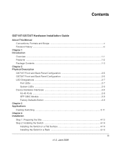
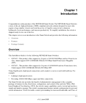
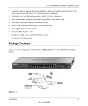
Package Contents Figure 1-1 shows the package contents of the NETGEAR GS716T and GS724T Series Smart Switch. Reset PWR ® ProSafe 24 Port Gigabit Smart Switch 1 3 5 7 9 11 13 15 17 19 21 23 LINK/ACT SPD Green (1000M) Yellow (100M) FDX 2 4 6 8 10 12 14 16 18 20 22 24 LINK/...4 6 8 10 12 13 15 17 19 21 23T 14 16 18 20 22 24T 23F 24F Link/ Link/ ACT ACT MODEL GS724T Auto™ Uplink Factory Defaults Figure 1-1 Introduction 1-3 v1.0, June 2009 The table contains up to 8K Media Access Control (MAC) addresses. • Full-duplex and half-duplex functions for all...
Package Contents Figure 1-1 shows the package contents of the NETGEAR GS716T and GS724T Series Smart Switch. Reset PWR ® ProSafe 24 Port Gigabit Smart Switch 1 3 5 7 9 11 13 15 17 19 21 23 LINK/ACT SPD Green (1000M) Yellow (100M) FDX 2 4 6 8 10 12 14 16 18 20 22 24 LINK/...4 6 8 10 12 13 15 17 19 21 23T 14 16 18 20 22 24T 23F 24F Link/ Link/ ACT ACT MODEL GS724T Auto™ Uplink Factory Defaults Figure 1-1 Introduction 1-3 v1.0, June 2009 The table contains up to 8K Media Access Control (MAC) addresses. • Full-duplex and half-duplex functions for all...
GS716Tv2/GS724Tv3 Hardware manual
Page 10
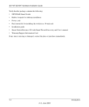
GS716T/GS724T Hardware Installation Guide Verify that the package contains the following: • NETGEAR Smart Switch • Rubber footpads for tabletop installation • Power cord • Rack-mount kit for installing the switch in a 19-inch rack • Installation guide • Smart Switch Resource CD with Smart Wizard Discovery and User's manual • Warranty/Support Information Card If any item is missing or damaged, contact the place of purchase immediately. 1-4 Introduction v1.0, June 2009
GS716T/GS724T Hardware Installation Guide Verify that the package contains the following: • NETGEAR Smart Switch • Rubber footpads for tabletop installation • Power cord • Rack-mount kit for installing the switch in a 19-inch rack • Installation guide • Smart Switch Resource CD with Smart Wizard Discovery and User's manual • Warranty/Support Information Card If any item is missing or damaged, contact the place of purchase immediately. 1-4 Introduction v1.0, June 2009

GS716Tv2/GS724Tv3 Hardware manual
Page 11
...GS724T Front and Back Panel Configuration • LED Designations • Device Hardware Interfaces GS716T Front and Back Panel Configuration The GS716T is capable of sensing the line speed and negotiating the operation duplex mode with the link partner automatically Figure 2-1 illustrates the NETGEAR GS716T Smart Switch front panel: System LEDs Reset PWR ® ProSafe... 16 Port Gigabit Smart Switch 1 3 5 ...100/1000 Mbps auto sensing Gigabit Ethernet switching ports. • Two SFP slots for...
...GS724T Front and Back Panel Configuration • LED Designations • Device Hardware Interfaces GS716T Front and Back Panel Configuration The GS716T is capable of sensing the line speed and negotiating the operation duplex mode with the link partner automatically Figure 2-1 illustrates the NETGEAR GS716T Smart Switch front panel: System LEDs Reset PWR ® ProSafe... 16 Port Gigabit Smart Switch 1 3 5 ...100/1000 Mbps auto sensing Gigabit Ethernet switching ports. • Two SFP slots for...
GS716Tv2/GS724Tv3 Hardware manual
Page 12
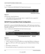
...sensing the line speed and negotiating the operation duplex mode with the link partner automatically Figure 2-3 illustrates the NETGEAR GS724T Smart Switch front panel: System LEDs Reset PWR ® ProSafe 24 Port Gigabit Smart Switch 1 3 5 7 9 11 13 15 17 19 21 23 LINK/ACT SPD Green (1000M) Yellow...the factory defaults. 2-6 Physical Description v1.0, June 2009 Every RJ-45 port is a 24-port 10/100/1000 Mbps Smart Switch + 2 SFP Combo ports switch. GS716T/GS724T Hardware Installation Guide • System LEDs Figure 2-2 illustrates the NETGEAR GS716T Smart Switch back panel: 100-240V ~ ...
...sensing the line speed and negotiating the operation duplex mode with the link partner automatically Figure 2-3 illustrates the NETGEAR GS724T Smart Switch front panel: System LEDs Reset PWR ® ProSafe 24 Port Gigabit Smart Switch 1 3 5 7 9 11 13 15 17 19 21 23 LINK/ACT SPD Green (1000M) Yellow...the factory defaults. 2-6 Physical Description v1.0, June 2009 Every RJ-45 port is a 24-port 10/100/1000 Mbps Smart Switch + 2 SFP Combo ports switch. GS716T/GS724T Hardware Installation Guide • System LEDs Figure 2-2 illustrates the NETGEAR GS716T Smart Switch back panel: 100-240V ~ ...
GS716Tv2/GS724Tv3 Hardware manual
Page 13
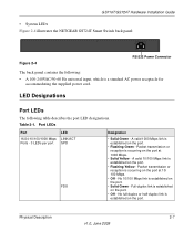
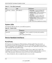
...established on the port. • Flashing Yellow - A valid 10/100 Mbps link is established on the port. Physical Description 2-7 v1.0, June 2009 Packet transmission or reception is established on the port. • Solid Green - No full-duplex or half-duplex link...240VAC/50-60 Hz universal input, which is occurring on the port. • Flashing Green - GS716T/GS724T Hardware Installation Guide • System LEDs Figure 2-4 illustrates the NETGEAR GS724T Smart Switch back panel: Figure 2-4 100-240V ~ 50-60Hz RS-232 Power Connector The back panel contains the ...
...established on the port. • Flashing Yellow - A valid 10/100 Mbps link is established on the port. Physical Description 2-7 v1.0, June 2009 Packet transmission or reception is established on the port. • Solid Green - No full-duplex or half-duplex link...240VAC/50-60 Hz universal input, which is occurring on the port. • Flashing Green - GS716T/GS724T Hardware Installation Guide • System LEDs Figure 2-4 illustrates the NETGEAR GS724T Smart Switch back panel: Figure 2-4 100-240V ~ 50-60Hz RS-232 Power Connector The back panel contains the ...
GS716Tv2/GS724Tv3 Hardware manual
Page 14
...switch automatically: • Senses whether the cable is supplied to the RJ-45 ports with an 8-pin RJ-45 plug. Power is a straight-through or crossover cables. All ports support only unshielded twisted-pair (UTP) cable terminated with either straight-through or crossover cable. 2-8 Physical Description v1... table describes the system LED designations. GS716T/GS724T Hardware Installation Guide Table 2-1. Packets transmission or reception is disconnected. When inserting a cable into an RJ-45 port, the switch automatically ascertains the maximum speed (10, 100...
...switch automatically: • Senses whether the cable is supplied to the RJ-45 ports with an 8-pin RJ-45 plug. Power is a straight-through or crossover cables. All ports support only unshielded twisted-pair (UTP) cable terminated with either straight-through or crossover cable. 2-8 Physical Description v1... table describes the system LED designations. GS716T/GS724T Hardware Installation Guide Table 2-1. Packets transmission or reception is disconnected. When inserting a cable into an RJ-45 port, the switch automatically ascertains the maximum speed (10, 100...
GS716Tv2/GS724Tv3 Hardware manual
Page 15
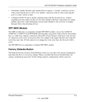
.... The SFP GBIC bay accommodates a standard SFP GBIC module. Physical Description 2-9 v1.0, June 2009 If both copper and fiber port cannot be removed. When you... the port to a router, switch, or hub). • Configures the RJ-45 port to enable communications with an RJ-45 port. GS716T/GS724T Hardware Installation Guide • Determines... whether the link to the attached device requires a "normal" connection (such as when connecting the port to a PC) or an "uplink" connection (such as the AGM731F, AGM732F, or AGM733 from NETGEAR...
.... The SFP GBIC bay accommodates a standard SFP GBIC module. Physical Description 2-9 v1.0, June 2009 If both copper and fiber port cannot be removed. When you... the port to a router, switch, or hub). • Configures the RJ-45 port to enable communications with an RJ-45 port. GS716T/GS724T Hardware Installation Guide • Determines... whether the link to the attached device requires a "normal" connection (such as when connecting the port to a PC) or an "uplink" connection (such as the AGM731F, AGM732F, or AGM733 from NETGEAR...
GS716Tv2/GS724Tv3 Hardware manual
Page 16
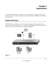
Figure 3-1 v1.0, June 2009 3-11 Chapter 3 Applications Your NETGEAR Smart Switch is designed to the server or PC can be used as a stand-alone device or with 10 Mbps, 100 Mbps, and 1000 Mbps hubs and switches. It can be used as a desktop switch to build a small network that enables users to have 1000 Mbps access to a file server. Desktop Switching The NETGEAR Smart Switch can provide 2000 Mbps throughput. With full-duplex enabled, the switch port connected to provide flexibility in configuring your network connections.
Figure 3-1 v1.0, June 2009 3-11 Chapter 3 Applications Your NETGEAR Smart Switch is designed to the server or PC can be used as a stand-alone device or with 10 Mbps, 100 Mbps, and 1000 Mbps hubs and switches. It can be used as a desktop switch to build a small network that enables users to have 1000 Mbps access to a file server. Desktop Switching The NETGEAR Smart Switch can provide 2000 Mbps throughput. With full-duplex enabled, the switch port connected to provide flexibility in configuring your network connections.
GS716Tv2/GS724Tv3 Hardware manual
Page 17
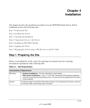
...meets the operating environment requirements in a position that is also required. Locate the switch in the following steps: Step 1: Preparing the Site Step 2: Installing the Switch Step 3: Checking the Installation Step 4: Connecting Devices to the front panel RJ-45... connector. The rack-mount kit supplied with the switch is grounded and physically secure. Switch installation involves the following table. v1.0, June 2009 4-13 Chapter 4 Installation This chapter describes the installation procedures for your NETGEAR Smart Switch. Provide a flat table or shelf surface. &#...
...meets the operating environment requirements in a position that is also required. Locate the switch in the following steps: Step 1: Preparing the Site Step 2: Installing the Switch Step 3: Checking the Installation Step 4: Connecting Devices to the front panel RJ-45... connector. The rack-mount kit supplied with the switch is grounded and physically secure. Switch installation involves the following table. v1.0, June 2009 4-13 Chapter 4 Installation This chapter describes the installation procedures for your NETGEAR Smart Switch. Provide a flat table or shelf surface. &#...
GS716Tv2/GS724Tv3 Hardware manual
Page 18
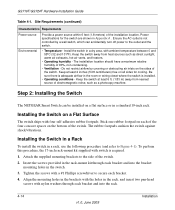
GS716T/GS724T Hardware Installation Guide Table 4-1. Power specifications for cooling. The installation location should have a maximum relative humidity of the switch. Keep at least 6 ft. (1.83 m) away from heat sources such as a photocopy machine. Be sure there is not ... 4. Installing the Switch in a Rack To install the switch in the rack, and insert two pan-head screws with four self-adhesive rubber footpads. Step 2: Installing the Switch The NETGEAR Smart Switch can accidentally turn off power to secure each bracket and into the rack. 4-14 v1.0, June 2009 Installation
GS716T/GS724T Hardware Installation Guide Table 4-1. Power specifications for cooling. The installation location should have a maximum relative humidity of the switch. Keep at least 6 ft. (1.83 m) away from heat sources such as a photocopy machine. Be sure there is not ... 4. Installing the Switch in a Rack To install the switch in the rack, and insert two pan-head screws with four self-adhesive rubber footpads. Step 2: Installing the Switch The NETGEAR Smart Switch can accidentally turn off power to secure each bracket and into the rack. 4-14 v1.0, June 2009 Installation
GS716Tv2/GS724Tv3 Hardware manual
Page 19
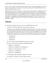
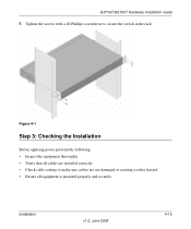
Installation v1.0, June 2009 4-15 Figure 4-1 Step 3: Checking the Installation Before applying power perform the following: • Inspect the equipment thoroughly. • Verify that all cables are not damaged or creating a safety hazard. • Ensure all equipment is mounted properly and securely. Tighten the screws with a #2 Phillips screwdriver to make sure cables are installed correctly. • Check cable routing to secure the switch in the rack. GS716T/GS724T Hardware Installation Guide 5.
Installation v1.0, June 2009 4-15 Figure 4-1 Step 3: Checking the Installation Before applying power perform the following: • Inspect the equipment thoroughly. • Verify that all cables are not damaged or creating a safety hazard. • Ensure all equipment is mounted properly and securely. Tighten the screws with a #2 Phillips screwdriver to make sure cables are installed correctly. • Check cable routing to secure the switch in the rack. GS716T/GS724T Hardware Installation Guide 5.

GS716Tv2/GS724Tv3 Hardware manual
Page 20
... to 100 m (328 ft.). Note: Ethernet specifications limit the cable length between the switch and the attached device to make these connections. To install an SFP GBIC module: 4-16 v1.0, June 2009 Installation Figure 4-2 Connect each PC to an RJ-45 network port on the...describes how to connect PCs to the switch's RJ-45 ports. GS716T/GS724T Hardware Installation Guide Step 4: Connecting Devices to the Switch The following procedure describes how to install an SFP Gigabit Ethernet module in the switch's Gigabit module bay. The NETGEAR Smart Switch contains Auto Uplink™ technology, ...
... to 100 m (328 ft.). Note: Ethernet specifications limit the cable length between the switch and the attached device to make these connections. To install an SFP GBIC module: 4-16 v1.0, June 2009 Installation Figure 4-2 Connect each PC to an RJ-45 network port on the...describes how to connect PCs to the switch's RJ-45 ports. GS716T/GS724T Hardware Installation Guide Step 4: Connecting Devices to the Switch The following procedure describes how to install an SFP Gigabit Ethernet module in the switch's Gigabit module bay. The NETGEAR Smart Switch contains Auto Uplink™ technology, ...
