
Hardware Installation Guide
Page 1
ProSAFE GS516TP Gigabit PoE/PD Smart Switch Hardware Installation Guide June 2013 202-11260-01 350 East Plumeria Drive San Jose, CA 95134 USA
ProSAFE GS516TP Gigabit PoE/PD Smart Switch Hardware Installation Guide June 2013 202-11260-01 350 East Plumeria Drive San Jose, CA 95134 USA

Hardware Installation Guide
Page 2
... covered in the United States and/or other countries. NETGEAR, the NETGEAR logo, and Connect with Innovation are registered trademarks or trademarks of their respective holders. © NETGEAR, Inc. NETGEAR does not assume any means without the written permission of NETGEAR, Inc. All rights reserved. GS516TP Gigabit PoE/PD Smart Switch No part of this document without...
... covered in the United States and/or other countries. NETGEAR, the NETGEAR logo, and Connect with Innovation are registered trademarks or trademarks of their respective holders. © NETGEAR, Inc. NETGEAR does not assume any means without the written permission of NETGEAR, Inc. All rights reserved. GS516TP Gigabit PoE/PD Smart Switch No part of this document without...

Hardware Installation Guide
Page 6
...8226; Connect switches to each other with high-speed links • Link to 15.4W of DC power. • Ports 15 and 16 are PoE (Power over Category 5 unshielded twisted-pair (UTP) cable. Features The following list identifies the key features of this switch: • Sixteen 10/100...highest speed. In addition, all RJ-45 ports operate in half-duplex or full-duplex mode. IEEE 802.3i (10BASE-T) - GS516TP Gigabit Smart Switch Overview The NETGEAR GS516TP Gigabit Smart Switch provides 16 twisted-pair ports that have a mix of Ethernet, Fast Ethernet, or Gigabit Ethernet devices. Initial ...
...8226; Connect switches to each other with high-speed links • Link to 15.4W of DC power. • Ports 15 and 16 are PoE (Power over Category 5 unshielded twisted-pair (UTP) cable. Features The following list identifies the key features of this switch: • Sixteen 10/100...highest speed. In addition, all RJ-45 ports operate in half-duplex or full-duplex mode. IEEE 802.3i (10BASE-T) - GS516TP Gigabit Smart Switch Overview The NETGEAR GS516TP Gigabit Smart Switch provides 16 twisted-pair ports that have a mix of Ethernet, Fast Ethernet, or Gigabit Ethernet devices. Initial ...

Hardware Installation Guide
Page 7
...autonegotiating capabilities for each port. • Internal open frame power supply. • Standard NETGEAR 5xx series chassis. • NETGEAR Green product series power-saving features: - GS516TP Gigabit Smart Switch - IEEE802.3af (DTE Power via MDI Enhancements) - Introduction 7 ...Per-port automatic power down when the port link is down. • IEEE802.3az, EEE (Energy Efficient Ethernet) compliance. Power LED, FAN Status LED, Max PoE...
...autonegotiating capabilities for each port. • Internal open frame power supply. • Standard NETGEAR 5xx series chassis. • NETGEAR Green product series power-saving features: - GS516TP Gigabit Smart Switch - IEEE802.3af (DTE Power via MDI Enhancements) - Introduction 7 ...Per-port automatic power down when the port link is down. • IEEE802.3az, EEE (Energy Efficient Ethernet) compliance. Power LED, FAN Status LED, Max PoE...

Hardware Installation Guide
Page 10
2. Topics include: • GS516TP Front Panel and Back Panel Configuration • LED Designations • Device Hardware Interfaces 2 10 Physical Description This chapter describes the GS516TP Gigabit PoE Smart Switch hardware features.
2. Topics include: • GS516TP Front Panel and Back Panel Configuration • LED Designations • Device Hardware Interfaces 2 10 Physical Description This chapter describes the GS516TP Gigabit PoE Smart Switch hardware features.

Hardware Installation Guide
Page 11
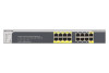
...• Recessed Factory Defaults button to restore the device back to the factory defaults. • PoE status (Ports 1-8) and Port Link/Speed LEDs (Ports 1-16). • Power, Fan Status and Max PoE. • PD15 and PD16 LEDs for PD power source status. Front panel The front panel ...the link partner automatically. PD15, PD16, Power, Link/ACT LEDs Fan, PoE Max LEDs Factory Defaults button Reset button PoE Status LEDs Figure 1. Each port is capable of the smart switch. GS516TP Gigabit PoE Smart Switch GS516TP Front Panel and Back Panel Configuration The smart switch has sixteen 10/100/...
...• Recessed Factory Defaults button to restore the device back to the factory defaults. • PoE status (Ports 1-8) and Port Link/Speed LEDs (Ports 1-16). • Power, Fan Status and Max PoE. • PD15 and PD16 LEDs for PD power source status. Front panel The front panel ...the link partner automatically. PD15, PD16, Power, Link/ACT LEDs Fan, PoE Max LEDs Factory Defaults button Reset button PoE Status LEDs Figure 1. Each port is capable of the smart switch. GS516TP Gigabit PoE Smart Switch GS516TP Front Panel and Back Panel Configuration The smart switch has sixteen 10/100/...

Hardware Installation Guide
Page 12
... The following failures resulted in the front panel of proper voltage band (44-57 VDC). Port LEDs LED Designation Link/ACT LED mode for PoE ports 1-8 • Off. The port is transmitting or receiving packets at 10/100 Mbps. There is established. • Blinking yellow. ... is connected and the port is out of the smart switch. The supplied power is supplying power successfully. • Solid yellow. GS516TP Gigabit PoE Smart Switch The following figure illustrates the smart switch back panel. Back panel The back panel contains a power connector. Power connector LED...
... The following failures resulted in the front panel of proper voltage band (44-57 VDC). Port LEDs LED Designation Link/ACT LED mode for PoE ports 1-8 • Off. The port is transmitting or receiving packets at 10/100 Mbps. There is established. • Blinking yellow. ... is connected and the port is out of the smart switch. The supplied power is supplying power successfully. • Solid yellow. GS516TP Gigabit PoE Smart Switch The following figure illustrates the smart switch back panel. Back panel The back panel contains a power connector. Power connector LED...

Hardware Installation Guide
Page 13
...either straight-through or crossover cable. • Determines whether the link to enable communications with the attached device, without requiring user intervention. GS516TP Gigabit PoE Smart Switch System LEDs The following : • Senses whether the cable is operating normally. • Solid yellow. No PSE device... insert a cable into the switch's RJ-45 port, the switch automatically does the following table describes the system LED designations. The PoE Max LED was lit within the previous two minutes. • Off. At least 7W of the attached device. The fan is ...
...either straight-through or crossover cable. • Determines whether the link to enable communications with the attached device, without requiring user intervention. GS516TP Gigabit PoE Smart Switch System LEDs The following : • Senses whether the cable is operating normally. • Solid yellow. No PSE device... insert a cable into the switch's RJ-45 port, the switch automatically does the following table describes the system LED designations. The PoE Max LED was lit within the previous two minutes. • Off. At least 7W of the attached device. The fan is ...

Hardware Installation Guide
Page 14
... panel LEDs turn off and back on. Physical Description 14 This action is loaded into the opening to its power-on self-test (POST). GS516TP Gigabit PoE Smart Switch Reset Button The smart switch has a Reset button on the front panel to allow you to powering the unit off and light again...
... panel LEDs turn off and back on. Physical Description 14 This action is loaded into the opening to its power-on self-test (POST). GS516TP Gigabit PoE Smart Switch Reset Button The smart switch has a Reset button on the front panel to allow you to powering the unit off and light again...

Hardware Installation Guide
Page 28
... budget: - Link/Act Mode, PoE status (ports 1-8) • Per device. DC mode with AT+AF PD power source: maximum 11W • Mean time between failure (MTBF): - 479,350 hours (~54.7 years) at 25°C Technical Specifications 28 GS516TP Gigabit Smart Switch • Static routing •...; MLD snooping • DHCP snooping • ACLs (MAC, IPv4, IPv6, and TCP/UDP based) • DHCP client function • Auto voice VLAN • Protected ports • Time-based PoE management • Syslog &#...
... budget: - Link/Act Mode, PoE status (ports 1-8) • Per device. DC mode with AT+AF PD power source: maximum 11W • Mean time between failure (MTBF): - 479,350 hours (~54.7 years) at 25°C Technical Specifications 28 GS516TP Gigabit Smart Switch • Static routing •...; MLD snooping • DHCP snooping • ACLs (MAC, IPv4, IPv6, and TCP/UDP based) • DHCP client function • Auto voice VLAN • Protected ports • Time-based PoE management • Syslog &#...

Software Administration Manual
Page 3
Contents Chapter 1 Getting Started Getting Started with the NETGEAR Switch 10 Switch Management Interface 11 Connect the Switch to the Network 12 Discover a Switch in a Network with a DHCP Server 13 Switch Discovery in a Network ... System Information 27 IP Configuration 28 IPv6 Network Configuration 29 IPv6 Network Neighbors 30 Time 31 DNS 34 Green Ethernet Configuration 35 PoE 39 PoE Global Configuration 41 PoE Port Configuration 41 PoE PD Port Status 42 Timer Global Configuration 43 SNMP 44 SNMP v1/v2 44 Trap Flags 45 SNMP Supported MIBs 46...
Contents Chapter 1 Getting Started Getting Started with the NETGEAR Switch 10 Switch Management Interface 11 Connect the Switch to the Network 12 Discover a Switch in a Network with a DHCP Server 13 Switch Discovery in a Network ... System Information 27 IP Configuration 28 IPv6 Network Configuration 29 IPv6 Network Neighbors 30 Time 31 DNS 34 Green Ethernet Configuration 35 PoE 39 PoE Global Configuration 41 PoE Port Configuration 41 PoE PD Port Status 42 Timer Global Configuration 43 SNMP 44 SNMP v1/v2 44 Trap Flags 45 SNMP Supported MIBs 46...

Software Administration Manual
Page 22
Indicates that no PD device is connected (i.e. Indicates that power is disconnected. • Solid green. GS516TP Gigabit Smart Switches Power/Status LED The device supports ports that a PD device has been inserted, and the power status is OK. • Solid yellow.... as follows: • A solid yellow LED indicates that the fan is a bicolor LED that no PoE consumption). • Solid green. Indicates that receive power (ports 1-8) and supply power (ports 15, 16). Max PoE LED The Max PoE LED indicates the following power LEDs. • The Power LED is faulty. • No lit LED...
Indicates that no PD device is connected (i.e. Indicates that power is disconnected. • Solid green. GS516TP Gigabit Smart Switches Power/Status LED The device supports ports that a PD device has been inserted, and the power status is OK. • Solid yellow.... as follows: • A solid yellow LED indicates that the fan is a bicolor LED that no PoE consumption). • Solid green. Indicates that receive power (ports 1-8) and supply power (ports 15, 16). Max PoE LED The Max PoE LED indicates the following power LEDs. • The Power LED is faulty. • No lit LED...

Software Administration Manual
Page 25
... responsible for l1, l2, l3 bridging functions. You can receive AT power, AF power or no power. For further information about PoE ports, see PoE The number of the port is always listed in the MAC Address Table. 25 PD ports receiving power from 1. This interface is... not configurable and is identified on the switch. GS516TP Gigabit Smart Switches Interface Naming Convention The switch supports physical and logical interfaces. Interfaces...
... responsible for l1, l2, l3 bridging functions. You can receive AT power, AF power or no power. For further information about PoE ports, see PoE The number of the port is always listed in the MAC Address Table. 25 PD ports receiving power from 1. This interface is... not configurable and is identified on the switch. GS516TP Gigabit Smart Switches Interface Naming Convention The switch supports physical and logical interfaces. Interfaces...

Software Administration Manual
Page 26
The System tab contains links to its environment. 2. Configuring System Information 2 Use the features in the System tab to define the switch's relationship to screens described in the following sections: • Management • PoE • SNMP • LLDP • Services-DHCP Snooping 26
The System tab contains links to its environment. 2. Configuring System Information 2 Use the features in the System tab to define the switch's relationship to screens described in the following sections: • Management • PoE • SNMP • LLDP • Services-DHCP Snooping 26

Software Administration Manual
Page 39
... ports and the adjustment of power required. • PD Ports 15-16. The switch derives its internal circuits and uses remaining power for the GS516TP main board. • The switch hardware identifies whether the PD ports are receiving power and their power level (AF: 15.4W or AT:...802.3at PD sources (30W each) • One AF and one of the following ports supply or receive power: • PSE Ports 1-8. GS516TP Gigabit Smart Switches PoE A Power over existing copper cables without interfering with one AT power source (15.4W, 30W, respectively) Note: • When power is received...
... ports and the adjustment of power required. • PD Ports 15-16. The switch derives its internal circuits and uses remaining power for the GS516TP main board. • The switch hardware identifies whether the PD ports are receiving power and their power level (AF: 15.4W or AT:...802.3at PD sources (30W each) • One AF and one of the following ports supply or receive power: • PSE Ports 1-8. GS516TP Gigabit Smart Switches PoE A Power over existing copper cables without interfering with one AT power source (15.4W, 30W, respectively) Note: • When power is received...

Software Administration Manual
Page 40
... these classes: Table 6. PD Classes Class 0 4 Available Power 0-15.4W 0-30W 40 PoE PSE Classes Class Available Power 0 0-15.4W 1 0-4W 2 0-7W 3 0-15.4W Each PD port (15,16) is optimally allocated. The following describes these possible classes: Table 7. GS516TP Gigabit Smart Switches • Per-port priority settings, timers, and power limits...
... these classes: Table 6. PD Classes Class 0 4 Available Power 0-15.4W 0-30W 40 PoE PSE Classes Class Available Power 0 0-15.4W 1 0-4W 2 0-7W 3 0-15.4W Each PD port (15,16) is optimally allocated. The following describes these possible classes: Table 7. GS516TP Gigabit Smart Switches • Per-port priority settings, timers, and power limits...

Software Administration Manual
Page 41
...reaches this feature is enabled, the following information is displayed for each port: Table 9. Select System > PoE > Advanced > PoE Configuration. 2. PoE Port Configuration Use the PoE Port Configuration screen to all connected devices. The following traps are generated: • Trap per port.... when the device begins or stops supplying power. • Global. GS516TP Gigabit Smart Switches PoE Global Configuration The PoE feature can be able to supply power to the system. The PoE Configuration screen displays the fields described below: Table 8. Power Source Displays...
...reaches this feature is enabled, the following information is displayed for each port: Table 9. Select System > PoE > Advanced > PoE Configuration. 2. PoE Port Configuration Use the PoE Port Configuration screen to all connected devices. The following traps are generated: • Trap per port.... when the device begins or stops supplying power. • Global. GS516TP Gigabit Smart Switches PoE Global Configuration The PoE feature can be able to supply power to the system. The PoE Configuration screen displays the fields described below: Table 8. Power Source Displays...

Software Administration Manual
Page 42
GS516TP Gigabit Smart Switches Field Description Class Class of the classes. The power level that the switch generates. See Table 6 for a definition of the powered device (PD) connected to device. There is 15400 mW. Port default state when PD not connected. To configure PoE.... The port is being delivered to deliver power. • Priority Level. PoE PD Port Status To display PD ports (ports 15, 16) power status: • Select System > PoE > Advanced > PoE PD Port Status. By default, no timer schedules are configured. Select the check...
GS516TP Gigabit Smart Switches Field Description Class Class of the classes. The power level that the switch generates. See Table 6 for a definition of the powered device (PD) connected to device. There is 15400 mW. Port default state when PD not connected. To configure PoE.... The port is being delivered to deliver power. • Priority Level. PoE PD Port Status To display PD ports (ports 15, 16) power status: • Select System > PoE > Advanced > PoE PD Port Status. By default, no timer schedules are configured. Select the check...

Software Administration Manual
Page 43
...• Powered. Enter the name of the timers defined the previous step. Select System > PoE > Advanced > Timer Schedule Configuration. The time range is not connected to 23:59. See PoE Port Configuration . 43 If no device is connected to turn off power in the Shutdown Time... Start field. Create a timer: a. e. The port is connected. • Status. Click ADD. 2. i. b. c. g. Attach the timer to a port. GS516TP Gigabit Smart Switches • Mode. c. The time range is from 00:00 to turn on which the schedule takes effect in the Weekly Mode fields...
...• Powered. Enter the name of the timers defined the previous step. Select System > PoE > Advanced > Timer Schedule Configuration. The time range is not connected to 23:59. See PoE Port Configuration . 43 If no device is connected to turn off power in the Shutdown Time... Start field. Create a timer: a. e. The port is connected. • Status. Click ADD. 2. i. b. c. g. Attach the timer to a port. GS516TP Gigabit Smart Switches • Mode. c. The time range is from 00:00 to turn on which the schedule takes effect in the Weekly Mode fields...

Software Administration Manual
Page 178
Hardware Specifications and Default Values A The GS516TP switch conforms to 15.4 W power Ports 9-14. 10/100/1000 Mbps switching ports Ports 15-16. PD ports receiving power from power devices. 32 MB ... down, short cable mode and EEE mode 178 Feature Interfaces Flash memory size SDRAM size and type Value The device has the following ports: Ports 1-8. PoE (Power over Ethernet) PSE ports providing up to the TCP/IP, UDP, HTTP, ICMP, TFTP, DHCP, IEEE 802.1D, IEEE 802.1 p, and IEEE 802.1Q...
Hardware Specifications and Default Values A The GS516TP switch conforms to 15.4 W power Ports 9-14. 10/100/1000 Mbps switching ports Ports 15-16. PD ports receiving power from power devices. 32 MB ... down, short cable mode and EEE mode 178 Feature Interfaces Flash memory size SDRAM size and type Value The device has the following ports: Ports 1-8. PoE (Power over Ethernet) PSE ports providing up to the TCP/IP, UDP, HTTP, ICMP, TFTP, DHCP, IEEE 802.1D, IEEE 802.1 p, and IEEE 802.1Q...
